R E S E A R C H
Open Access
Low-complexity interference variance
estimation methods for coded multicarrier
systems: application to SFN
Marius Caus
1*, Ana I Perez Neira
1,2and Markku Renfors
3Abstract
For single-frequency network (SFN) transmission, the echoes coming from different transmitters are superimposed at the reception, giving rise to a frequency selective channel. Although multicarrier modulations lower the dispersion, the demodulated signal is sensitive to be degraded by inter-symbol interference (ISI) and inter-carrier interference (ICI). In view of this, we use channel coding in conjunction either with filter bank multicarrier (FBMC) modulation or with orthogonal frequency division multiplexing (OFDM). To deal with the loss of orthogonality, we have devised an interference-aware receiver that carries out a soft detection under the assumption that the residual interference plus noise (IN) term is Gaussian-distributed. To keep the complexity low, we propose to estimate the variance of the IN term by resorting to data-aided algorithms. Experimental results show that regardless of the method, FBMC provides a slightly better performance in terms of coded bit error rate than OFDM, while the spectral efficiency is increased when FBMC is considered.
1 Introduction
With the aim of making an efficient use of the spec-trum, 3GPP has introduced the multimedia broadcast and multicast service (MBMS) for delivering multimedia con-tent to mobile users [1]. Among the possible transmission schemes, we focus on single-frequency network (SFN), which has also been widely studied in the DVB-T digital TV context. In a SFN, the frequency reuse factor is one, and thus, the user equipment (UE) receives several de-layed versions of the same signal, giving rise to an artificial multipath channel. In this regard, the use of the orthog-onal frequency division multiplexing (OFDM) technique facilitates the implementation of the SFN concept. It must be mentioned that depending on the inter-site distance and the system parameters such as the sampling frequency and the subcarrier spacing, OFDM may not present a good balance between the resilience against multipath fading and the spectral efficiency. In other words, the min-imum cyclic prefix (CP) length that is required to absorb
*Correspondence: [email protected]
1Department of Signal Theory and Communications, Universitat Politecnica de Catalunya(UPC), Barcelona 08034, Spain
Full list of author information is available at the end of the article
the last echo may lead to a dramatic spectral efficiency re-duction. However, if the CP is not long enough to encom-pass the maximum channel excess delay, the demodulated signal will suffer from inter-symbol interference (ISI) and inter-carrier interference (ICI). To overcome the OFDM limitations, we can resort to the filter bank multicarrier (FBMC) modulation [2]. The FBMC technique is designed to achieve maximum bandwidth efficiency since no re-dundancy is transmitted in the form of a CP. Furthermore, the subcarrier signals follow the Nyquist pulse shaping idea, which makes the FBMC modulation more robust against narrow-band interferences and synchronization errors than OFDM. However, the channel is dispersive at the subcarrier level and thus the equalization is not a straightforward task; see, e.g., [3,4]. For further details about how OFDM and FBMC compare, we address the reader to [5].
To the best of the authors’ knowledge, FBMC-based SFNs have not been considered in the literature ear-lier. In this work, we assume the worst case scenario in which orthogonality is not restored neither in OFDM nor FBMC cases. To combat the drawbacks of this definitely challenging scenario, OFDM and FBMC transmission are combined with channel coding. Bearing this in mind, we
propose mapping the received symbols into soft bits un-der the assumption that the residual interference plus noise (IN) is Gaussian-distributed. Simulation-based re-sults show that the FBMC system is able to give the same or slightly better performance than OFDM in terms of bit error rate (BER) while the spectral efficiency significantly increases.
It is worth mentioning that previous works have com-pared coded FBMC and OFDM modulations in the presence of severe multipath fading [6-8]. These studies highlight the importance of characterizing the statistical information of the signal that corrupts the demodulated data. In this sense, we have formulated an analytical model for the additive noise and interference effects, as well as evaluated the complexity that is required to get a closed-form expression of its variance. The order of the com-plexity may render the solution impractical. Therefore, we opt to use low-complexity estimation methods for the variance of the IN term. In this work, we have described two data-assisted strategies. The complexity analysis re-veals that the proposed methods alleviate the complexity with respect to the cost of implementing the ideal receiver, which perfectly characterizes the variance of the IN term. In view of the above discussion, the contributions of this paper are summarized as follows:
• We evaluate the complexity and memory
requirements of each variance estimator. In addition, the coded BER is assessed when each method is applied. The complexity costs and the system performance of the ideal receiver, which perfectly characterizes the variance of the IN term, are also provided. By confronting the ideal receiver with the receiver that relies on the variance estimation, we are able to provide insight into performance degradation when the complexity is reduced.
• We carry out a comparison between OFDM and FBMC in the context of SFN transmission. Regardless of which estimator is implemented, the numerical results reveal that FBMC slightly outperforms OFDM in terms of coded BER. In this sense, multi-tap equalization plays a key role in FBMC systems to improve link reliability especially in highly frequency-selective channels. This allows us to conclude that the FBMC modulation scheme is a potential candidate to be used in a SFN. To the best of our knowledge, FBMC has not been considered earlier in the literature for SFN.
The remainder of the paper is organized as follows. In Section 2, we describe the system model in a SFN. The loss of orthogonality in the FBMC context is studied in Section 3. Based on the analysis in Section 3, we design in Section 4 a receiver that is interference aware. To alleviate
the complexity, two data-assisted methods are investi-gated to estimate the variance of the IN term. Section 5 analyzes the complexity and the memory that is required to estimate the variance by each method. The coded BER is evaluated in Section 6 when the interference-aware re-ceiver is applied in OFDM and FBMC systems. Finally, Section 7 draws the conclusions.
2 System model
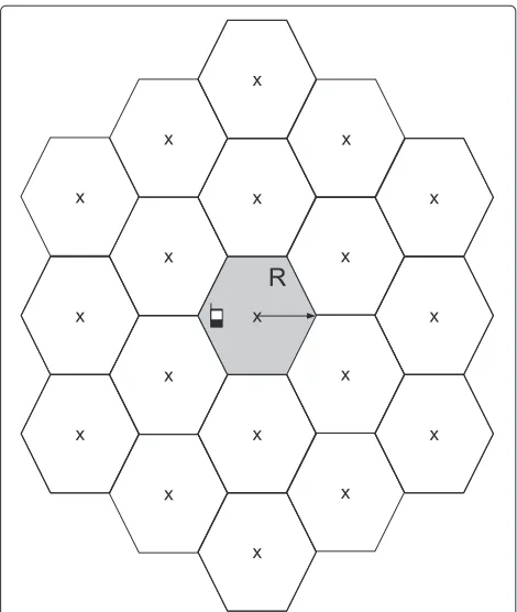
In this work, we consider the SFN represented in Figure 1. Since the synchronization issues are out of the scope of this paper, we assume that all the transmitters are perfectly time- and frequency-synchronized. Nevertheless, the sig-nals that come from the first- and second-order neighbors will give rise to an artificial multipath. More distant base stations (BSs) are ignored, so in the considered scenario, 19 BSs are transmitting in the same band.
Assuming that the UE is synchronized with the nearest BS, the received signal can be written as a function of the virtual channel asr[n]=hv[n]∗s[n]+w[n], where
r[n]= 19
i=1 1
√
Li
s[n−τi]∗hi[n]+w[n] . (1)
Heres[n] is the signal transmitted by all the BSs andw[n] is the additive white Gaussian noise. The term τi stands for the delay of theith transmitter with respect to the BS
of reference, which can be identified without loss of gener-ality with any index. The propagation conditions between theith transmitter and the UE are modeled by the channel impulse response (CIR)hi[n] and by the combined effect of the path loss and the shadowing, which is expressed as Li(dB) = ¯Li(dB)+Xi(dB). The variableXi(dB)accounts for the shadowing, and it follows a Gaussian distribution with zero mean and standard deviationσx. By contrast,
¯
Li(dB) is a distance-dependant term given by L¯i(dB) = 128.1+37.6log10(di), wheredidenotes the distance to the ith transmitter in kilometers [9]. With the aim of studying the most general case, we consider that the UE receives several delayed versions of the signal broadcasted by a given transmitter. Therefore,hi[n] is modeled as a tapped delay line, which indicates that the channel between the receiver and any transmitter is frequency selective.
3 SFN based on FBMC transmission
This section aims at introducing the expressions for FBMC when the orthogonality is not restored in a SFN. The transmitted signal in the FBMC context is given by
s[n]=
∞
k=−∞
M−1
m=0 fm
n−kM 2
ym[k] (2)
fm[n]=p[n]ej2Mπm
n−L−21, (3)
where p[n] is the prototype pulse, M is the number of subcarriers, andmis the subcarrier index. To avoid confu-sion, the sampling indexnis used for the high-rate signals while the low-rate signals utilize the indexk. Due to its good time and frequency localization properties, we opt to design the pulse as [10] details having fixed the length toL = 4M. The symbolsym[k] are generated according to the offset quadrature amplitude modulation (OQAM) scheme. Hence, they can be understood as real pulse amplitude modulation (PAM) symbols at double symbol rate and multiplied by a phase term, which is defined as follows:
θm[k]=
1 m+k even j m+k odd
. (4)
Thenym[k]=dm[k]θm[k], wheredm[k] is the real PAM symbol transmitted on the mth subcarrier. At the re-ceiver side, the UE sees the transmitted signal through the corrupted version described in (1). To recover the information multiplexed on each subband, the received samples are fed into a bank of filters and then the out-puts are downsampled to obtain the low-rate signals. The
output of theqth filter, i.e.,zq[k]= r[n]∗fq∗[−n]
↓M/2, can be compactly formulated as
zq[k]= q+1
m=q−1
ym[k]∗gqm[k]+wq[k] (5)
with
gqm[k]= fm[n]∗hv[n]∗fq∗[−n]
↓M/2 (6)
wq[k]= w[n]∗fq∗[−n]
↓M/2. (7)
The operation(.)↓x performs a decimation by a factor ofx. Expression (5) indicates that symbols are degraded by ISI and ICI. Thanks to the good spectral confine-ment of the pulses, ICI mainly comes from the adjacent subbands. In addition, the equivalent channel impulse responses gqm[k]
are assumed different from zero for−2 ≤ k ≤ 2. The energy of the interference terms corresponding to|k| ≥ 3 can be neglected. To draw an analogy with OFDM, we formulate the demodulated data in a matrix way. Stacking the outputs of the analysis filter bank, we obtain
z[k]=[z0[k]. . .zM−1[k]]T = 2
t=−2
G[t]y[k−t]+w[k]
(8)
where
y[k]=[θ0[k]d0[k]. . . θM−1[k]dM−1[k]]T (9)
w[k]=[w0[k]. . .wM−1[k]]T. (10) The matrix G[t] accommodates the coupling between carriers at thetth time instant. The element located at the mth row andlth column is given by
[G[t]]ml=
gml[t] if l∈Sm 0 otherwise
, 0≤m,l≤M−1,
(11)
whereSm = {modM(m−1),m, modM(m+1)}contains three indexes. Note that modM(x) accounts for the modulusMofx.
Considering briefly the OFDM system model when the orthogonality is destroyed, the vector at the FFT output reads as
z[k]=H[0]y[k]+H[1]y[k−1]+w[k] . (12)
used in the FBMC case exhibits better frequency localiza-tion properties than the sinc-like shape. As a consequence, the matricesH[0],H[1] are not so sparse as{G[t]}.
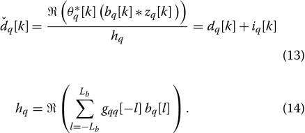
To combat the frequency selectivity of the channel in FBMC systems, it is customary to apply a multi-tap subcarrier equalizer. Since the orthogonal properties are satisfied in the real field, we extract the real part of the equalizer output after compensating the phase term. Based on that and denoting bybq[k] the equalizer used in the qth subband, which is designed according to the zero-forcing criterion [3], the symbol estimation can be expressed as
It is worth mentioning thatbq[k] is different from zero for−Lb ≤ k ≤ Lb, thushqcorresponds to the term that weighs the desired symbol after being equalized. Expand-ing (13), we differentiate between desired and undesired information. The additive IN termiq[k] includes contri-butions of ICI, ISI, and noise. The closed-form expression is given by widely studied, we refrain from formulating the IN term in the OFDM context. Its expression can be computed as [11] details.
4 Interference-aware receiver
Bearing in mind the system model described in Section 3, we devise a technique to decode the received message in the presence of ISI, ICI, and noise. To protect the informa-tion from the detrimental effects caused by the artificial multipath fading, the bits are encoded by means of a parallel concatenated coding scheme, which consists of two identical systematic encoders, the transfer function of which is G(D) =
1,11++DD2++DD33
. Next the coded bits are mapped as Figure 2 illustrates. Finally, the sequence of symbols is fed to the synthesis filter bank (SFB), which is in charge of frequency multiplexing the symbols. The symbol mapper and the synthesis filter bank stages will be different depending on the multicarrier modulation to be used.
At the receiver, the analysis filter bank (AFB) enables demodulating the information that is conveyed on each subband. The equalization stage, which is designed un-der the zero-forcing criterion for both OFDM and FBMC systems, is appended at the analysis filter bank output. At this point, the soft detection can be performed from the output of the equalizers. Bearing in mind (13), thea posteriorilog-likelihood ratios (LLRs) of the encoded bits cl, forl = 1,. . .,b, can be simplified using the Max-Log
wherebis the number of bits that constitutes the PAM symbols. The expression d : cl = 1 (d : cl = 0) defines the set of symbols whose lth bit is 1 (0). It is worth emphasizing that we have assumed that the bits are equiprobable and the interference plus noise term is a real-valued random variable that is Gaussian-distributed, i.e.,iq[k]∼ N(0,σq2). The same approach is followed in [8]. Note that the mean of the IN term is always zero. Un-der the assumption that symbols have zero mean, we can infer from (15) thatEiq[k]
which can be proven by demonstrating that E
Sincew[n] is modeled as a complex circularly symmet-ric Gaussian variable with mean 0 and varianceN0, then E{ (w[n])} =E{(w[n])} =E{ (w[n])(w[n])} =0. From this definition, it follows that (18) and (19) are zero. With that we conclude the proof that demonstrates that
Eiq[k]
=0.
If the statistical information of the noise and the sym-bols, as well as the instantaneous channel, is perfectly known, it is possible to formulate σq2 in a closed-form expression as follows:
We have assumed that the symbols are zero-mean, independent, and uncorrelated with the noise, i.e.,
Edm[k]dq[n] = Es
2δm,qδk,n andE
dm[k]wq[n] = 0,
∀m,q,k,n. The factor 2 highlights that the PAM sym-bols are obtained after staggering in-phase and quadrature components of QAM symbols whose variance isEs. Re-garding the filtered noise, the analytical expression of its variance can be found in [4,12]. Based on (20) we should first calculate the coefficientsgqm[k]
, which are given by
gqm[k]=
whereLvis the maximum channel excess delay of the vir-tual channel. Even knowing ejπqkαk
qm[t]
beforehand, it can be deduced from (21) that the complexity cost in terms of multiplications is 2Lv. Taking into account which values ofgqm[k] are different from zero, the total number of operations is approximately 30LvM. According to the expressions provided in [11], the complexity in the OFDM case is in the order of M3. From the perspective of re-ducing the complexity, we propose to estimate the power using two different methods.
4.1 Direct decision method
The first method to estimate (20) consists in comput-ing the empirical expectation ofiq[k] over a period,T, in which the channel conditions do not substantially vary. The estimation boils down to compute the following ex-pression
It can be readily verified that the complexity required to compute (23) is substantially reduced with respect to that required to obtain the theoretical expression of (20). In order to get the instantaneous value of the IN term, it is mandatory to subtract the data symbols from the equalized signals, i.e.,iq[k]= ˇdq[k]−dq[k]. To perfectly compute the term iq[k], the receiver needs to know the transmitted data beforehand. Hence, this method relies on the transmission of T pilot sequences in the form of a preamble. Nevertheless, this may imply transmitting longer training sequences than those exclusively used for channel estimation and synchronization purposes, which would decrease the spectral efficiency. To overcome this drawback, the method proposed in this section refrains from using pilots. As a consequence, the IN term is ap-proximated to ˇiq[k]= ˇdq[k]−s0q[k], where s0q[k] is an estimation of dq[k]. It must be mentioned that the reli-ability of the proposed estimator crucially relies on the decisions made from the equalized signals. If the deci-sions are not correct, the variance estimation will sub-stantially deviate from the real value. In this sense, the simplest option consists in detecting symbols according to the maximum likelihood (ML) criterion, which yields this estimator
whereXis the modulation alphabet. One way to evaluate the quality of the estimator is to check if it is unbiased. To this end, we calculate the conditional expectation of
k = 0,. . .,T−1, is any symbol of the constellation dia-gram. That is,s0q[k]∈ Xfor 0 ≤ k ≤ T −1. Taking into account that symbols are zero-mean and independent, we can write the expectation in this form
Eσˇq2,0|s0q[0]. . .s0q[T−1]= T1T−1 k=0
Edq[k]−s0q[k] 2
+Eiq[k]2
= 1 T
T−1
k=0
Edq[k]−s0q[k] 2
+σq2.
(25)
Unless the decisions are correct, i.e.,dq[k]= s0q[k], the estimator will be biased as (25) shows. This highlights the importance of regenerating the message as accurately as possible.
4.2 Refined direct decision method
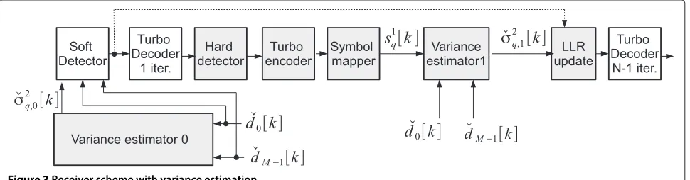
We have empirically observed that the estimator derived in Section 4.1 gives satisfactory results when the mod-ulation order is low, e.g., 2PAM. On the contrary, for highorder modulations, the BER curves exhibit an er-ror floor. To remedy this, it is clear that the estimator has to be refined. In this sense, the approach that we have followed is based on regenerating the sequence of trans-mitted symbols from the outputs of the turbo decoder. That is, already detected bits from the initial iteration are fed into the turbo encoder stage and then the coded bits are mapped to obtain the OQAM symbols. From Figure 3 it can be inferred that the refined estimation is equivalent to
ˇ
σq2,1= 1 T
T−1
k=0
dˇq[k]−s1q[k] 2
. (26)
Notice that the extrinsic LLRs computed by the first turbo decoder are not directly forwarded to the second turbo decoder to be used asa prioriinformation. That is because the termσˇq2,0, which is computed as (24) specifies, may excessively deviate from the real value. If so, errors
will propagate on subsequent turbo iterations since the decoding algorithms are sensitive to the variance errors. It is also important to remark that, contrary to [13], the esti-mated symbols are not used to cancel out the interferences but to get a more accurate estimation of the transmit-ted symbols when compared to the approach followed in Section 4.1. As (25) indicates, the lower the symbol er-ror rate is, the lower is the bias. The reason why we have discarded canceling out the interferences has to do with the complexity burden that is required to calculate the coefficients of the equivalent channelsgqm[k]
.
It is worth mentioning that the symbols in FBMC sys-tems are modulated at a rate twice that of the symbols in OFDM. Hence, for a fixed window, the number of symbols that are used to calculate (23), (24), and (26) will beT/2 in the OFDM case.
5 Comparison of different estimation techniques
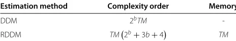
In this section, we compare the two estimators described in Section 4. In this sense, the Table 1 summarizes the order of the complexity and the memory that is approx-imately required by each method. The analysis that has been conducted to get the values of Table 1 is detailed hereinafter.
5.1 DDM
The direct decision method relies on performing an ex-haustive search over all the elements of the modulation alphabet as (24) highlights. Provided thatbbits are used to represent any point of the constellation diagram, then the number of norms that has to be calculated is equal to 2bTM. On the positive side, the approach followed in Section 4.1 does not need to store any data.
5.2 RDDM
The complexity required to implement the refined direct decision method is tantamount to computing the com-plexity of the grey blocks in Figure 3. Towards this end, we first analyze σˇq2,0. According to (24), the number of norms to be computed is 2bTM, wherebis the number
Table 1 Complexity order and memory requirements of computing the variance of the IN term in all the subcarriers
Estimation method Complexity order Memory
DDM 2bTM
-RDDM TM2b+3b+4 TM
DDM, direct decision method; RDDM, refined direct decision method.
of bits that constitutes the symbols. The next process that contributes to the increase of complexity is the con-version from soft bits to binary data. Considering that a single mapping only takes one operation together with the fact that the code rate is set to rcode = 1/3 im-plies performing b3TM operations. Then each bit has to be coded again by concatenating two identical systematic convolutional codes. Then it follows that the turbo code computes 23bTMcoded bits, and each one is obtained af-ter performing four logical operations. To regenerate the message, the coded bits are mapped into OQAM symbols by performingMT look-up operations. As (26) indicates, the refined estimation requires computingMT norms. In
the last step, we multiply LLR(cl|ˇdq[k]) by
ˇ σq2,0
ˇ
σq2,1, which takes TM divisions and TM multiplications. According to the values gathered in Table 1, the complexity costs whenb = 2 results approximately in 14TMoperations. Bearing in mind the complexity analysis conducted in Section 4, the number of operations to get the exact value of
σq2
is in the order ofM3and 30LvMwhen the OFDM and the FBMC modulation scheme is considered, respec-tively. This highlights that although the strategy devised in Section 4.2 is the most complex, the method is still in-teresting because there is a good prospect ofLv andM2 being higher thanT. Therefore, the refined direct decision method is likely to be more efficient than the compu-tation of the real variance. Unlike what happens in the DDM, the regenerated message has to be stored so that it can be loaded later on to estimate the variance. As a re-sult, there should be enough available memory to saveTM symbols.
A feature that is common to all the algorithms described in Section 4 is that they do not operate in real time. That is, the variance is estimated after receivingT consecutive multicarrier symbols and storing the decision variables
ˇ
dq[k]
for 0 ≤ k ≤ T −1 and 0 ≤ q ≤ M−1. This observation reveals that in addition to the memory re-quirements that are summarized in Table 1, the receiver has to reserve some additional space to saveTMequalized symbols.
6 Numerical results
In this section, we compare OFDM and FBMC in the SFN scenario depicted in Figure 1 where the cell radius is equal
toR =1 km. Hence, the user is confined in the coverage area of a single transmitter while the exact position ran-domly varies for each channel realization. Regarding the system parameters, the 10-MHz bandwidth is split into M=1,024 subbands, out of which 600 are active. The car-rier frequency is 2 GHz and the sampling frequency is set to 15.36 MHz. The power delay profile of{hi[n]}obeys the ITU Vehicular A (VehA) or the ITU Vehicular B (VehB) models, and we assume that the channel is invariant for T = 20 consecutive FBMC symbols or, equivalently, for T = 10 consecutive OFDM symbols. The shadowing standard deviation isσx = 8 dB. As for the decoder, we employ the MAX-LOG-MAP algorithm withN =4 itera-tions. The symbols belong to 16-QAM, which means that the real symbolsdq[k]are 4-PAM. The assessment has been made in terms of BER against the energy bit-to-noise ratio (Eb/N0), which is defined as
Eb/N0=
19
i=1 1 Li
Es M+MCP
4rcodeN0
, (27)
where the noise samples are generated as followsw[n]∼
CN(0,N0) andEs is the symbol energy. The constant 4 accounts for the number of bits that constitutes the 16-QAM symbols. It is worth mentioning that CP = 0 for FBMC systems and CP= M4 in the OFDM case.
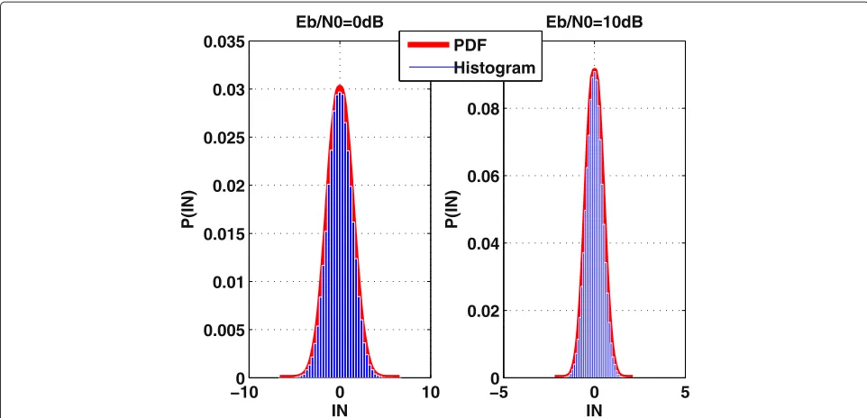
−100 0 10 0.005
0.01 0.015 0.02 0.025 0.03 0.035
IN
P(IN)
Eb/N0=0dB
−50 0 5
0.02 0.04 0.06 0.08 0.1
IN
P(IN)
Eb/N0=10dB PDF
Histogram
Figure 4Probability density function and histogram ofiq[k]forq=410.The propagation conditions obey the VehB channel model.
different subcarriers. Based on this, we have assumed that the Gaussian approximation holds true when detecting the symbols.
6.1 Benchmark
Before evaluating the impact of variance estimation meth-ods described in Section 4, we depict in Figure 5 the BER curves when the variance of iq[k] is perfectly estimated. When the power delay profile of the channel obeys the ITU Vehicular A model, the FBMC system does not ben-efit from performing a multi-tap equalization because the
0 2 4 6 8 10 12 14 16 10−6
10−4 10−2 100
Eb/N0 (dB)
BER
OFDM FBMC L
b=0 FBMC L
b=1
Figure 5BER versusEb
N0when the receiver is based on perfect IN variance estimation.The propagation conditions obey the VehA channel model.
channel frequency response at the subcarrier level is prac-tically flat. With the parameters used in this scenario, the maximum channel excess delay satisfies Lv ≤ 216, and therefore, the demodulated signals are free of ISI when OFDM is considered. The improvement of FBMC with re-spect to OFDM for Eb
N0 ≤ 14 dB is a consequence of the
energy wastage that implies the CP transmission.
In Figure 6, we asses the system performance when the channel is modeled according to the ITU Vehicular B model. Now the gap between the multi-tap and single-tap linear equalization is widened. The reason lies in the fact
0 2 4 6 8 10 12 14 10−6
10−5 10−4 10−3 10−2 10−1 100
Eb/N0 (dB)
BER
OFDM FBMC Lb=0 FBMC L
b=1 (OFDM) IC (FBMC L
b=0) IC
Figure 6BER versusEb
that the channel coherence bandwidth has reduced since the maximum channel excess delay is upper bounded as followsLv ≤ 484. As a result, the transmission based on the OFDM technique does not succeed in avoiding inter-block interference (IBI). By setting CP= M4, the IBI is reduced to a higher extend but not enough to give better performance than the FBMC modulation that equalizes the channel with three taps per subband. These results re-veal that it is of paramount importance to mitigate the residual interference as much as possible. This obser-vation has motivated us to test one alternative receiver that performs a perfect interference cancelation (IC). That is, we get rid of the interference from vectors (12) and (13) before they are fed into the channel decoding stage. Then, the noise is the only source of interference. The curves in Figure 6 indicate that the improvement brought by the perfect IC is marginal. As it is pointed out in Section 4, the complexity required to estimate the interfer-ence may be too high, which provides further arguments in favor of the receiver that is based on estimating the variance.
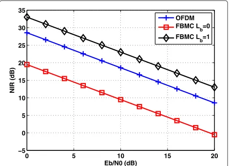
To further justify the results provided in Figure 6, we have pictured in Figure 7 the noise-to-interference ratio (NIR) averaged over all subcarriers. Borrowing the no-tation from (20), the metric in the FBMC case is given by
NIR= 1
600
q∈Sa
E θq∗[k]bTqwq[k]
2
Es
2
(m,t)=(q,0)
θq∗[k]θm[k−t]bTqgqm[t]
2,
(28)
where Sa contains the indices of those subcarriers that are active. Figure 7 confirms that multi-tap equaliza-tion removes the interference more effectively than the
0 5 10 15 20 −5
0 5 10 15 20 25 30 35
Eb/N0 (dB)
NIR (dB)
OFDM FBMC L
b=0 FBMC Lb=1
Figure 7Average NIR versusEb
N0.The propagation conditions obey the VehB channel model.
0 5 10 15 20 10−8
10−6 10−4 10−2 100
Eb/N0 (dB)
BER
(OFDM) DDM (OFDM) RDDM (FBMC L
b=0) DDM (FBMC L
b=0) RDDM (FBMC L
b=1) DDM (FBMC Lb=1) RDDM
Figure 8BER versusEb
N0when the receiver implements different IN variance estimation methods for the VehA channel model.
single-tap counterpart in high-frequency selective chan-nels. Hence, the results of Figure 7 are in accordance with the coded BER versus Eb
N0 curves.
Regarding bandwidth efficiency, the spectral efficiency reaches 1.20 bits/s/Hz for the FBMC case. The OFDM counterpart results in 0.96 bits/s/Hz.
6.2 Evaluation of the proposed interference-aware receiver
In this section, we evaluate the performance of the re-ceiver based on the variance estimation. The window used by all the methods described in Section 4 encompasses 20 FBMC symbols or, equivalently, 10 OFDM symbols. Figures 8 and 9 highlight that the plots obtained when the RDDM is applied are shifted to the right when compared to Figures 5 and 6. That is because the turbo decoder per-forms three iterations instead of four. As Figure 3 shows,
0 5 10 15 20 10−6
10−5 10−4 10−3 10−2 10−1 100
Eb/N0 (dB)
BER
(OFDM) DDM (OFDM) RDDM (FBMC L
b=0) DDM (FBMC Lb=0) RDDM (FBMC Lb=1) DDM (FBMC Lb=1) RDDM
Figure 9BER versusEb
0 2 4 6 8 10 12 14 16 18 10−4
10−3 10−2 10−1 100
Eb/N0 (dB)
SER (OFDM) DDM
(OFDM) RDDM (FBMC Lb=0) DDM
(FBMC Lb=0) RDDM
(FBMC Lb=1) DDM
(FBMC Lb=1) RDDM
Figure 10SER before and after performing the initial turbo iteration versusEb
N0for the VehA channel model.
one iteration is devoted to estimating the variance. Recall-ing (25), we can assert that the degradation is also related to the errors committed when performing the symbol mapping after re-encoding the bits obtained at the out-put of the initial turbo iteration. By examining Figure 9, we can conclude that the degradation in FBMC systems is between 1 and 2 dB when the equalizers perform a multi-tap filtering. In the single-tap case, the degradation is substantially higher. Taking into consideration Figure 7, it seems that the cause is related to the insufficient in-terference mitigation capabilities exhibited by single-tap equalization in severe propagation conditions. In order to improve the performance, the interference has to be more effectively rejected. Notice that the curves associated with the receiver based on the DDM exhibit an error floor. The reason is that the tentative decisions used in (24) are too erroneous.
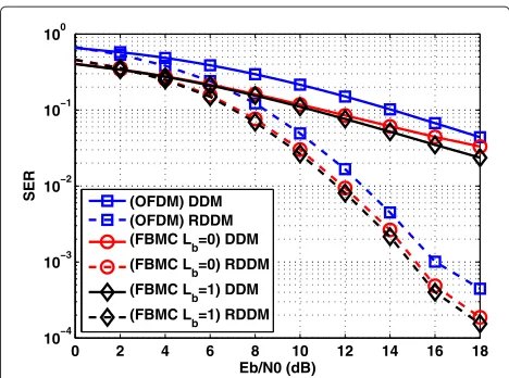
0 2 4 6 8 10 12 14 16 18
10−4 10−3 10−2 10−1 100
Eb/N0 (dB)
SER (OFDM) DDM
(OFDM) RDDM (FBMC Lb=0) DDM
(FBMC Lb=0) RDDM
(FBMC Lb=1) DDM
(FBMC Lb=1) RDDM
Figure 11SER before and after performing the initial turbo iteration versusEb
N0for the VehB channel model.
To support the results of Figures 8 and 9, we plot in Figures 10 and 11 the symbol error rate (SER) that is observed when the transmitted data is estimated ac-cording to the procedure followed by the DDM and the RDDM. Since the decoding algorithms are sensitive to the variance deviations, the coded BER performance re-lies on the accuracy with which the transmitted mes-sage is regenerated as (25) demonstrates. The results of Figures 10 and 11 can be understood as the evaluation of the SER at the input and the output of the initial turbo iteration. In Figure 10, the plots associated with the RDDM are equal or less than 1 dB apart. Hence, all the techniques suffer a similar deterioration for es-timating the variance as Figure 8 shows. By contrast, when the selectivity of the channel becomes stronger as it happens in the scenario simulated with Vehicular B channel in Figure 9, the FBMC modulation combined with the single-tap zero forcing equalizer does not achieve competitive results when the variance is estimated. By observing Figure 11, it becomes clear that the degrada-tion is related to the increased SER, which causes less reliable estimation. As it has been previously pointed out, the tentative decisions made when the DDM is ap-plied are not reliable. This is confirmed in Figures 10 and 11.
7 Conclusions
Competing interests
The authors declare that they have no competing interests.
Acknowledgements
This work has received funding from the Spanish Ministry of Economy and Competitiveness (Ministerio de Economia y Competitividad) under project TEC2011-29006-C03-02 (GRE3N-LINK-MAC) and from the Catalan Government (2009SGR0891). This work was partially supported by the European Commission through the Emphatic project (ICT-318362).
Author details
1Department of Signal Theory and Communications, Universitat Politecnica
de Catalunya(UPC), Barcelona 08034, Spain.2Centre Tecnologic de
Telecomunicacions de Catalunya (CTTC), Castelldefels, Barcelona 08860, Spain.
3Department of Electronics and Communications Engineering, Tampere
University of Technology, Tampere 33101, Finland.
Received: 18 March 2013 Accepted: 20 September 2013 Published: 27 October 2013
References
1. ETSI 3rd Generation Partnership Project (3GPP), 3GPP TS 25346, Introduction of the multimedia broadcast multicast service (MBMS) in the radio access network (RAN). stage 2 (release 11) (2012)
2. P Siohan, C Siclet, N Lacaille, Analysis and design of OFDM/OQAM systems based on filterbank theory. Signal Process. IEEE Trans. 50(5), 1170–1183 (2002)
3. T Ihalainen, TH Stitz, M Rinne, M Renfors, Channel equalization in filter bank based multicarrier modulation for wireless communications. EURASIP J. Appl. Signal Process.2007, 049389 (2007)
4. D Waldhauser, L Baltar, J Nossek, inIEEE 9th Workshop on Signal Processing Advances in Wireless Communications, 2008. SPAWC 2008. MMSE subcarrier equalization for filter bank based multicarrier systems (IEEE, 2008), pp. 525–529
5. B Farhang-Boroujeny, OFDM versus filter bank multicarrier. Signal Process. Mag. IEEE28(3), 92–112 (2011)
6. T Ihalainen, T Stitz, A Viholainen, M Renfors, inProceedings of the IEEE International Symposium on Circuits and Systems, 2006. ISCAS 2006
Performance comparison of LDPC-coded FBMC and CP-OFDM in beyond 3G context (IEEE, 2006), pp. 21–24
7. G Ndo, P Siohan, M Hamon, in2010 IEEE 72nd Vehicular Technology Conference Fall (VTC 2010-Fall)A comparison between coded OFDM/OQAM and CP-OFDM modulations over multipath channels (IEEE, 2010), pp. 1–5
8. G Ndo, P Siohan, MH Hamon, in2010 International Conference on Advanced Technologies for Communications (ATC)
Performances of coded OFDM/OQAM over PLC impaired by impulsive and colored noise (IEEE, 2010), pp. 1–6
9. International Telecommunication Union, inRecommendation ITU-R M.1225Guidelines for the evaluation of radio transmission technologies for IMT-2000 (ITU, 1997)
10. M Bellanger, in2001 IEEE International Conference on Acoustics, Speech, and Signal Processing, 2001. Proceedings. (ICASSP ’01).vol. 4 Specification and design of a prototype filter for filter bank based multicarrier transmission (IEEE, 2001), pp. 2417–2420
11. X Sun, Q Wang, L Cimini, L Greenstein, D Chan, ICI/ISI-aware beamforming for MIMO-OFDM wireless systems. Wireless Commun. IEEE Trans. 11, 378–385 (2012)
12. M Caus, Transmitter-receiver designs for highly frequency selective channels in MIMO FBMC systems. Signal Process. IEEE Trans. 60(12), 6519–6532 (2012)
13. R Zakaria, D Le Ruyet, in2011 IEEE 22nd International Symposium on Personal Indoor and Mobile Radio Communications (PIMRC)On spatial data multiplexing over coded filter-bank multicarrier with ML detection (IEEE, 2011), pp. 1391–1395
doi:10.1186/1687-6180-2013-163
Cite this article as: Caus et al.:Low-complexity interference variance estimation methods for coded multicarrier systems: application to SFN. EURASIP Journal on Advances in Signal Processing20132013:163.
Submit your manuscript to a
journal and benefi t from:
7Convenient online submission
7Rigorous peer review
7Immediate publication on acceptance
7Open access: articles freely available online
7High visibility within the fi eld
7Retaining the copyright to your article