Space-Time Turbo Coded Modulation:
Design and Applications
Djordje Tujkovic
Centre for Wireless Communications (CWC), University of Oulu, P.O. Box 4500, Tutkijantie 2E, FIN-90014 Oulu, Finland Email: [email protected]
Markku Juntti
Centre for Wireless Communications (CWC), University of Oulu, P.O. Box 4500, Tutkijantie 2E, FIN-90014 Oulu, Finland Email: [email protected]
Matti Latva-aho
Centre for Wireless Communications (CWC), University of Oulu, P.O. Box 4500, Tutkijantie 2E, FIN-90014 Oulu, Finland Email: [email protected]
Received 1 June 2001 and in revised form 14 January 2002
A design method for recursive space-time trellis codes and parallel-concatenated space-time turbo coded modulation is pro-posed that can be applied to an arbitrary existing space-time trellis code. The method enables a large, systematic increase in coding gain while preserving the maximum transmit diversity gain and bandwidth efficiency property of the considered space-time trellis code. Applying the above method to Tarokh et al. space-space-time trellis codes, significant performance improvements can be obtained even with extremely short input information frames. The application of space-time turbo coded modulation to the space-frequency domain is also proposed in this paper. Exploiting the bandwidth efficient orthogonal frequency division modu-lation (OFDM), multiple transmit antennas and large frequency selectivity offered by typical low mobility indoor environments, the proposed space-frequency turbo coded modulation performs within 2.5 dB of the outage capacity for a variety of practical wideband multiple-input multiple-output (MIMO) radio channels.
Keywords and phrases:space-time coding, turbo coded modulation, OFDM modulation.
1. INTRODUCTION
The knowledge of the fact that increasing the codeword length of block codes or constraint length of convolutional codes leads to better performance dates back to Shannon theory [1]. It is also well known that in case of maximum-likelihood (ML) decoding the drawback of such a perfor-mance gain is the increased decoding complexity up to the point where decoding becomes physically unrealizable. Thus, the research in coding theory over the years has seen many proposals aiming at constructing powerful codes with large equivalent codeword or constraint lengths structured so to permit breaking the ML decoding into simpler partial decod-ing steps. Turbo codes [2] are the most recent of such an at-tempt, already accepted to be the result of a clever intuition built upon several concepts already established, rather than just a sudden apparition.
Turbo codes were originally introduced as binary error-correcting codes built from the parallel concatenation of two recursive systematic convolutional codes (RSC) exploiting a
suboptimal but very powerful iterative decoding algorithm, the so-called turbo decoding algorithm. However, it turned out that the method applied for this parallel concatenation is more general. The turbo principle is nowadays successfully applied in many detection/decoding problems such as serial concatenation, equalization, coded modulation, multi-user detection, joint interference suppression, and decoding.
Attempts to combine turbo codes with multilevel ampli-tude or phase modulations in order to improve transmis-sion spectral efficiency has brought many proposals of the so-called turbo coded modulations (TuCM) [3, 4, 5]. Be-hind all schemes is Ungerboeck’s trellis coded modulation (TCM) principle [6], now a well-established technique in digital communications, where significant coding gains are achieved through signal set expansion rather than sacrificing data rate or bandwidth efficiency.
techniques have been utilized in isolation bringing signifi-cant performance improvements by neutralizing detrimental effects of fading in wireless communication channels. If di-versity techniques are combined, more independent dimen-sions become available for information transfer and there-fore significantly more margin exists for system performance improvement.
During the past few years there has been a growing interest to combine the benefits of forward error control coding and antenna diversity. Many authors [8, 9, 10, 11] have demonstrated that under specific configuration [12], multiple-input multiple-output (MIMO) wireless channels enable increased information theoretic capacity compared to single antenna systems. The so-called space-time coding (STC) schemes are focused on merging antenna diversity with appropriate channel coding in order to achieve both coding and antenna diversity gains. One of the first design criteria for such codes were derived in [13]. However, the main impetus on research in the space-time coding area was done in [14] where powerful and bandwidth efficient Tarokh et al. space-time trellis codes (Tarokh-STTrC) were proposed. Unlike the Ungerboeck TCM approach where cod-ing gain is achieved through signal set expansion, in the space-time trellis coding approach expansion is done in an-tenna space. For example, TCM enables 2 bit/s/Hz with 8PSK modulation and a single transmit antenna while in the case
of STTrCs, the same bandwidth efficiency is achieved with
QPSK modulation and two transmit antennas. In quasi-static fading channels, with two transmit antennas, Tarokh-STTrCs were reported to have performance close to the out-age capacity.
With the handcrafted design of a low number of trellis states, Tarokh-STTrCs have the maximum diversity gain for a given number of transmit antennas but with a very poor coding gain. More extensive code search provided improved versions of STTrCs [15, 16] but no significant breakthrough has been achieved. Further performance improvement, ex-pected by increasing the code constraint length comes with the cost of increased ML decoding complexity. Due to the lack of systematic procedure for building STTrCs for a large number of trellis states it also turned out to be a tedious task. Recently, such an attempt [17] resulted in highly nonopti-mized codes as we will show.
In this paper, we propose the space-time turbo coded modulation (STTuCM), a signaling method that with lim-ited increase in decoding complexity enables a large, system-atic increase in coding gain while preserving the maximum transmit diversity gain of the underlined space-time trellis code. The method can be applied to an arbitrary STTrC and assumes the construction of an equivalent, recursive space-time trellis code (Rec-STTrC) which is then employed in the parallel concatenation with iterative decoding. Punctur-ing the outputs of component codes enables a considerable
improvement in power efficiency with no loss bandwidth
efficiency. We will show that STTuCM owes its good
per-formance to mainly two important features. First, relatively simple constituent Rec-STTrCs are optimized for both multi-antenna transmission and parallel concatenation. Second, a
distinctive feature in the proposed scheme is the bit-wise in-terleaving between the two constituent codes, resulting in the overall parallel-concatenated coding scheme that operates on the bit level, despite the fact that constituent codes have non-binary trellises.
In parallel, somewhat similar but independent work has been presented in [18, 19]. In [18], no puncturing was ap-plied resulting in a turbo code with a reduced data rate com-pared to constituent codes. In [19], the interleaving between two constituent codes was performed on the symbol level; we will show that symbol level interleaving considerably lim-its the performance improvements in comparison to bit level interleaving. We also outline the other attempts to apply the Turbo principle to MIMO systems [20, 21, 22], which can be mainly summarized as combinations of binary, single an-tenna turbo codes with spatial multiplexing at the transmit-ter and suboptimal ML demodulation and Turbo decoding at the receiver.
2. RECURSIVE SPACE-TIME TRELLIS CODES
Through the analytical upper-bounding technique in [23], it was shown that turbo codes do require recursive but not necessarily systematic component encoders to work prop-erly and that the implementation of recursive convolutional codes represents a distinctive feature of turbo codes. Parallel concatenated scheme built from recursive constituent codes has the sparse code distance spectrum similar to the type of code distance spectrum achieved by the “random-like” codes [23].
The originally proposed Tarokh-STTrCs are nonrecursive and therefore not suitable for interleaved code concatena-tions. For binary trellis codes, building an equivalent recur-sive code from a nonrecurrecur-sive convolutional code is straight-forward and is done by closing the feedback from the out-put to the inout-put of the encoders block diagram. For symbol level trellises, like in the STTrC case, there exist more than one possibility to close the feedback from an output to in-put. Moreover, translating the trellis diagrams to closed ana-lytic forms and sketching the corresponding block diagrams is not always straightforward. We propose the systematic way to build an equivalent recursive code from a nonrecursive trellis code based on the codes trellis diagram only. Closing the feedback on the codes block diagram introduces the in-finite impulse response of the transfer function. Alternative way to assure the infinite impulse response of the transfer function is to reorganize the input/output transitions of the nonrecursive, nonbinary codes trellis diagram in the way de-scribed below.
LetZbe the number of input bits to the STTrC encoder
during each trellis transition and let Q be the number of states in the nonrecursive codes trellis diagram. There are 2Z branches entering each node and the same number of differ-ent input symbols taking values in 0,1, . . . ,2Z−1. As STTrCs
are designed to have no parallel transitions, 2Z ≤ Qis
al-ways satisfied. LetP=Q/2Zbe the number of adjacent nodes
in the trellis within a group of nodes so that there are Q/P
branch in the trellis of recursive STTrC, assign the same cor-responding output symbols as for the equivalent nonrecur-sive STTrC. This will preserve the maximum diversity gain and the frame error rate (FER) of nonrecursive STTrC. For corresponding input symbols, follow the algorithm depicted in Figure 1.
(1) Start with the group G0 consisting of the first P
nodes in the trellis. Assign the array of input symbols [0,1, 2, . . . ,2Z−1] to branches consecutively departing from node
0. Assign the same array to the group of nextP−1 nodes.
(2) For each ofP nodes within groupGi,i = 1· · ·2Z −
1, assign the i symbols shifted array of input symbols to
branches consecutively departing from that node, that is, as-sign array [1,2, . . . ,2Z −1,0] to branches consecutively
de-parting from each node withinG1.
Following the above procedure, the equivalent recur-sive STTrC can be designed for an arbitrary nonrecurrecur-sive STTrC. Figures A.1, A.2, and A.3 in the appendix, show the proposed 4-state and 8-state QPSK, 8-state 8PSK, and 16-state 16QAM Rec-STTrCs for two transmit antennas de-signed upon Tarokh-STTrCs. Input/output transitions in the
tables are given in the form d/S1S2 where at one time
in-stant and given state, for input information symbol d,d ∈
{0,1, . . . ,2Z−1}, corresponding output symbols areS 1and
S2, transmitted from antennas 1 and 2, respectively. Output
symbols are given as the points in QPSK, 8PSK, and 16QAM constellation diagrams for codes in Figures A.1, A.2, and A.3, respectively. It can be easily verified that for the Rec-STTrCs in Figures A.1, A.2, and A.3 the input information sequence of Hamming weight 1 produces the codewords of the infi-nite length, that is, infiinfi-nite impulse response of the transfer function is achieved.
3. THE SYSTEM MODEL
3.1. The encoder
We consider a system employingNtransmit andMreceive
antennas. The block diagram of the proposed encoder is de-picted in Figure 2 as a parallel concatenation of two Rec-STTrCs followed by a block for puncturing and/or multi-plexing. The input bit information stream to the encoder is
first divided intoZ-bit long blocks and encoded by the
non-binary trellis of the first encoder. After being scrambled by pseudo-random bit-wise interleaving, it is again divided into
Z-bit blocks and encoded by the second constituent encoder.
The two blocks of N output symbols at each time instant
(one block from each component encoder, each block
hav-ingNsymbols from the complex constellation—one for each
transmit antenna) are then punctured and/or multiplexed
and associated toNtransmit antennas.
Both puncturing and multiplexing are done in parallel across antennas so that at one time instant, one of the
en-coders has full access to N transmit antennas. In case of
nonpuncturing, equivalent code-word length of a parallel-concatenated code is doubled so that the overall bandwidth
efficiency is halved. In case of puncturing, each component
encoder is sending only every secondN-symbol output block
G0={0, . . . , P−1}=
Figure1: Input symbols’ assignment.
?
Figure2: Block diagram of the encoder.
from its codeword, which is time multiplexed with every
other N-symbol output block from the other encoder. For
example, if the output of the first encoder is
S1=
Sk11Sk12· · ·Sk1N;Sk+111 Sk+112 · · ·Sk+11N;
Sk+211 Sk+212 · · ·Sk+21N;Sk+311 Sk+312 · · ·Sk+31N
(1)
and the output of the second encoder is
S2=
in case of puncturing, the sequence
S=Sk11Sk12· · ·S1Nk ;Sk+121 Sk+122 · · ·Sk+12N;
Sk+211 Sk+212 · · ·Sk+21N;Sk+321 Sk+322 · · ·Sk+32N
(3)
will be transmitted.Sk
enabove is the output symbol from
Symbol
MAP 1 sym/bit π1,2 bit/sym Symbol
MAP 2 +
−
L1 L1 ext ˜L2 apri
bit/sym π−1
1,2 sym/bit
L1 apri ˜L2 ext ˜L2
−
+
Figure3: Block diagram of the decoder.
timek. In this way, full bandwidth efficiency of component codes is preserved.
3.2. The interleaving
Pseudo-random bit-wise interleaving for the nonpuncturing case does not have any restrictions and has the same size as the input information frame in bits. In case of puncturing, it actually consists of two, half-length bit-wise interleavers
π1 andπ2. One interleaver is scrambling input bits on odd
input symbol positions, another is independent of the first one, scrambling the input bits on the even input symbol po-sitions. This will assure that due to puncturing all the input bits will contribute once and only once to the output code-word. Other than this constraint, both interleavers were cho-sen to be pseudo-random and bit-wise.
For example, forZ=3 and the input information frame
given as (b0b1b2;b3b4b5;b6b7b8;b9b10b11), one realization of theπ1-π2pair will result in the sequence (b8b6b0;b11b9b10; b2b1b7;b3b5b4) entering the second constituent encoder. In the case of single, pseudo-random symbol-wise interleaving [19], one realization of the interleaving will result in the se-quence (b9b10b11;b6b7b8;b3b4b5;b0b1b2) entering the second constituent encoder.
3.3. The decoder
The block diagram of the decoder is depicted in Figure 3. Nonbinary component codes are decoded by a symbol-by-symbol MAP algorithm as in [24]. To enable pseudo-random bit-wise interleaving, additional symbol-to-bit and bit-to-symbol reliability transforms are applied so the resultant en-coder and iterative (turbo) deen-coder operate on the bit level. The bit-wise scrambling improves the resolution of the im-plemented interleaving and on a fading channel increases the block Hamming distance.
Assume that information frame at the input of one of
the component encoders consists of Lbits denoted asb =
[b0b1b2· · ·bL−1]. As the component encoders are nonbinary,
input bit stream b is divided into Z-bit blocks forming a
frame of input symbols denoted as d = [d0d1d2· · ·dL/Z−1] where symboldk=[bkZbkZ+1· · ·b(k+1)Z−1],k=0, . . . , L/Z−1.
At the receiver end, for each component receiver antennam,
m = 1, . . . , M, received signal for whole input frame is de-noted as rm = [rm0rm1rm2· · ·rmK−1], whereK = 2L/Z in case
of nonpuncturing and K = L/Z in case of puncturing. At
discrete timek, the signal received by antennamis denoted
as
rk m=
N
n=1 αk
nmSken+ηkm, k=0, . . . , K−1, m=1, . . . , M, (4)
whereαk
nmare time varying path gains from transmit antenna
nto receive antennammodeled as samples of independent
zero mean complex Gaussian random variables with variance 0.5 per dimension. The path gains along different paths are
assumed to be noncorrelated.ηk
mare noise samples given as
independent samples of zero mean complex Gaussian
ran-dom variables with varianceσ2=N
0/2 per complex
dimen-sion. In (4), we assume e = 1 for k = 2c−1 and e = 2
fork = 2c,c = 1,2, . . . for both, nonpunctured and
punc-tured case. Complex symbolsSk
enhave the average energy of
Es for eachn = 1, . . . , N. To conform to the definition in [14] we define signal-to-noise ratio (SNR) per receive
an-tenna as SNR = NEs/N0. Prior to decoding, each received
vector rm is de-multiplexed into two vectors,re,m, e = 1,2 each contributed from one of two component encoders. In case of nonpuncturing these are r1,m = [rm0rm2rm4 · · ·rmK−2] and r2,m = [rm1rm3rm5· · ·rmK−1], K = 2L/Z, while in case of puncturing, punctured signals are exchanged with erasures
r1,m = [r0m0rm20rm4· · ·rmK−2] andr2,m = [0rm10rm30rm5· · ·rmK−1], K =L/Z.
For the sake of brevity we will repeat only the final results from [24] necessary for further understanding. Also we drop
subscriptedenoting component encoders, that is,rm =re,m
fore =1,2 andm= 1, . . . , M. The output of a symbol-by-symbol MAP algorithm is given as a posteriori probability
(APP) of input information symbol dk conditioned by
Prdk= bkZ· · ·b(k+1)Z−1
the subscript 2 denotes theZ-bit long binary representation
of the value in brackets;rkis thekth column of matrixr. The
constantξcan be eliminated by straightforward
normaliza-tion; χk andβk are results of forward and backward
recur-sions whileγkdenotes the branch transition probability for
stepkgiven as
where the first term in product (6) denotes APP of transmit-ted symbols at time instantk, the second term in the product is either one or zero depending on whether the encoder input [bkZ· · ·b(k+1)Z−1] is associated with the transition from state Sk−1 = q0to stateSk =qor not. The third term in product (6) is a priori probability of information symboldk
PrSk=q|Sk−1=q0
=Prdk= bkZ· · ·b(k+1)Z−1
. (7)
In case of iterative decoding, a priori probability is supplied by the other decoder which makes the iterative (turbo) de-coding algorithm suboptimal. This is done in all cases except the first iteration of the first decoder where no a priori infor-mation is available and therefore it is assumed that all input symbols are equally likely. The logarithm value of APP in (6) is calculated from
In case of puncturing, for time instances k in which
de-multiplexed vectorsrkare exchanged with erasures, the
log-arithm value of APP in (8) is set to 0. This means that at such time instances we cannot use channel outputs as we do not have them. Luckily at those time instances channel out-puts correspond to another decoder, which is therefore capa-ble of providing reliacapa-ble a priori probabilities that dominate the term in (6). As the component encoders are nonsystem-atic, the output of MAP in (5) comprises two terms instead of three, which is the case when component codes are sys-tematic. Two terms represent the extrinsic and a priori infor-mation. In the case that symbol-wise interleaving between constituent codes is employed, symbol-level extrinsic infor-mation is first extracted and symbol-wise interleaved to form a priori probability for the other symbol-by-symbol MAP decoder in (7). Therefore symbol-to-bit and bit-to-symbol
transforms in Figure 3 are avoided and the exchange of log-likelihood information between the two constituent decoders is done directly at the symbol level. We propose bit-wise in-terleaving between constituent encoders and therefore prior to bit-level extrinsic information extraction and bit-wise in-terleaving, additional symbol-to-bit reliability transform is applied in the form
producing a log-likelihood ratio for each information bitbl
for alll∈ {kZ, . . . ,(k+1)Z−1}andk=0, . . . , L/Z−1. Bit-level extrinsic information is now extracted
Lextbl=Lbl−Lapribl, (10)
whereLapri(bl) is a priori probability of the information bit bl. After being bit-wise interleaved it becomes ˜Lext and is passed through bit-to-symbol reliability transform to result in a priori probability for the second decoder to be used in (7) first decoding iteration of the first decoder,L1apriin Figure 3 is set to all zeros, as we do not have any a priori information for that stage of decoding. Symbol-to-bit reliability trans-form transfers the joint into marginal probabilities. Also due to bit-wise interleaving and de-interleaving, bit-level extrin-sic reliabilities can be assumed independent and therefore there is no loss of information when converting the symbol-to-bit reliabilities and vice versa. Symbol-symbol-to-bit and bit-to-symbol reliability transforms add negligible complexity to the iterative decoder but which we will see, have a crucial im-pact on performance.
4. APPLICATION TO NARROWBAND RADIO SYSTEMS In this section, we apply the proposed method to design an STTuCM based on Tarokh-STTrCs and evaluate the per-formance under two models of narrowband frequency flat Rayleigh fading channel models, namely the quasi-static and block fading channels. Narrowband transmission is assumed. Therefore, the results illustrate the performance in time divi-sion multiple access (TDMA) type systems, like the global system for mobile communications (GSM), IS-136, or en-hance data rates on GSM Evolution (EDGE). The perfor-mance comparisons between different schemes in all of the
following figures was done in terms of power efficiency
un-der the same bandwidth efficiencies and modulation levels.
8 9 10 11 12 13 14 15 16 17 18 19 SNR (dB)
10−2
10−1
100
FER
Tarokh-STTrC 4-state [14] Rec-STTrC 4-state
STTuCM 2×4-state Tarokh-STTrC iter=2 STTuCM 2×4-state Tarokh-STTrC iter=6 STTuCM 2×4-state Rec-STTrC iter=2 STTuCM 2×4-state Rec-STTrC iter=6
Figure 4: Quasi-static fading, nonpunctured scheme, bandwidth efficiency 1 bit/s/Hz, QPSK.
264 bit for QPSK, 8PSK, and 16QAM modulation formats, respectively. For turbo codes, this falls into the region of very low frame sizes. Two transmit and a single receive antenna are assumed in all simulations.
The quasi-static fading channel is the worst case of fading realization where fading is constant during the whole trans-mission of one frame and therefore no temporal diversity is available. In order to test the importance of recursive com-ponent codes to overall, parallel-concatenated code perfor-mance, in Figure 4 we compared the performance of 4-state Tarokh-STTrC and Rec-STTrC. When implemented alone, both codes have the same frame error rate (FER) which is shown by two almost overlapping curves. On the other hand, when implemented in parallel concatenation, Rec-STTrCs have 3 dB gain compared to Tarokh-STTrCs already after 6 iterations. The performance gain of the parallel concatenated scheme compared to the performance of the single compo-nent code is more than 4.5 dB but the penalty is halved band-width efficiency as nonpuncturing is implemented. Unlike the parallel concatenation of Tarokh-STTrCs where the gain of parallel concatenation saturates already after the second iteration, in case of Rec-STTrCs, increasing the number of it-erations above 6, additional gains are achieved. Therefore, we applied a total of 10 iterations in all of the following simula-tions.
In case of puncturing on quasi-static fading channels with extremely short frames, it has turned out that the best performance is achieved with the concatenation of the orig-inal Tarokh-STTrC and Rec-STTrC. This results from the availability to terminate both component encoders to the all-zero state at the end of each frame, though not with the same tail sequence. Figures 5 and 6 present the performance comparisons of STTuCM built as parallel concatenation of
9 10 11 12 13 14 15 16 17 18 19
SNR (dB) 10−2
10−1
100
FER
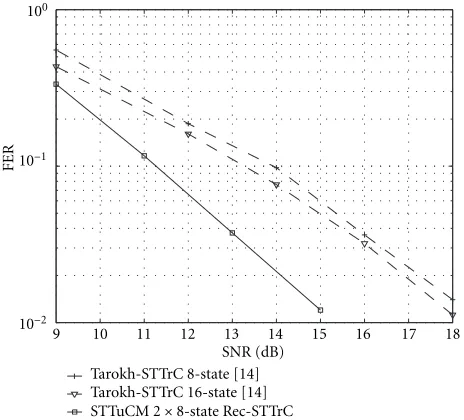
Tarokh-STTrC 8-state [14] Tarokh-STTrC 16-state [14]
STTuCM 2×8-state Tarokh&Rec-STTrC
Figure 5: Quasi-static fading, bandwidth efficiency 2 bit/s/Hz, QPSK.
15 16 17 18 19 20 21 22 23 24 25 SNR (dB)
10−2
10−1
FER
Tarokh-STTrC 8-state [14] Tarokh-STTrC 16-state [14]
STTuCM 2×8-state Tarokh&Rec-STTrC
Figure 6: Quasi-static fading, bandwidth efficiency 3 bit/s/Hz, 8PSK.
the two 8-state STTrCs one of the component codes being Rec-STTrC compared to 8-state and 16-state Tarokh-STTrCs for QPSK and 8PSK modulation formats, respectively. Punc-turing is implemented this time so that full bandwidth effi-ciency of constituent codes is preserved. Slopes of the sim-ulation curves on Figures 4, 5, and 6 prove that the pro-posed STTuCM preserves the maximum diversity gain with and without puncturing. Horizontal distance between par-allel curves is a measure of the additional coding gain. At
an FER level of 10−2STTuCM outperforms 16-state
Tarokh-STTrCs by 1 dB in both the QPSK and 8PSK case. At the usual
9 10 11 12 13 14 15 16 17 18 SNR (dB)
10−2
10−1
100
FER
Tarokh-STTrC 8-state [14] Tarokh-STTrC 16-state [14] STTuCM 2×8-state Rec-STTrC
Figure7: Block-2 fading, bandwidth efficiency 2 bit/s/Hz, QPSK.
performs within 1.5 dB and 2.2 dB of the 10% outage ca-pacity for the QPSK and 8PSK case, respectively (see [14] or Figure 10).
For many practical wireless systems the channel can be modeled as block fading. Enhanced data rates for GSM evo-lution (EDGE) system relies on bandwidth efficient 8PSK modulation but has adopted the same underlying GSM frame structure where data is organized into 4 (half rate) or 8 (full rate) bursts and where optional frequency hopping in between bursts is included in the standard.
The block fading model is in general suitable for fad-ing channels in which a certain block of adjacent transmit-ted symbols are affected by the highly correlated fading path gains. The length of the block may be considered as a first ap-proximation of the channels coherence time (single-carrier systems) or the channels coherence bandwidth (multi-carrier systems).
Figures 7 and 8 present the performance comparisons of STTuCM built as a parallel concatenation of two 8-state Rec-STTrCs compared with 8-state and 16-state Tarokh-STTrCs for QPSK and 8PSK modulations with two indepen-dent fading blocks per frame. In both cases, STTuCM
out-performs the 16-state Tarokh-STTrC by 3 dB at FER 10−2.
Figure 9 depicts the performance comparison of STTuCM built as a parallel concatenation of two, 16-state Rec-STTrCs compared with 16-state Tarokh-STTrC for 16QAM mod-ulation with two and four independent fading blocks per frame.
At FER 10−2, STTuCM outperforms Tarokh-STTrC by
more than 3.5 dB and 6 dB for two and four independent fading blocks per frame, respectively. As seen from [25, 26], an increase in the frame size severely deteriorates the perfor-mance of Tarokh-STTrCs while increasing the frame size of STTuCM improves the performance on channels with a con-siderable amount of temporal diversity.
14 15 16 17 18 19 20 21 22 23 24 SNR (dB)
10−2
10−1
100
FER
Tarokh-STTrC 8-state [14] Tarokh-STTrC 16-state [14] STTuCM 2×8-state Rec-STTrC
Figure8: Block-2 fading, bandwidth efficiency 3 bit/s/Hz, 8PSK.
15 16 17 18 19 20 21 22 23 24 25 26 SNR (dB)
10−2
10−1
100
FER
Tarokh-STTrC 16-state [14] block-2 fading Tarokh-STTrC 16-state [14] block-4 fading STTuCM 2×16-state Rec-STTrC block-2 fading STTuCM 2×16-state Rec-STTrC block-4 fading
Figure 9: Block-2, -4 fading, bandwidth efficiency 4 bit/s/Hz, 16QAM.
5. APPLICATION TO WIDEBAND RADIO SYSTEMS
Due to its high bandwidth efficiency and suitability for
high data rate wireless applications, orthogonal frequency division modulation (OFDM) was chosen as a modulation scheme for a physical layer in several new wireless standards, that is, digital audio and video broadcasting (DAB, DVB) in Europe [27, 28] and the three broadband wireless local area networks (WLAN), European HIPERLAN/2, American IEEE 802.11a, and Japanese MMAC [29].
exploiting the bandwidth efficient OFDM modulation was presented as a natural solution for future high data rates over wide band MIMO radio channels [30]. Large bandwidth and power efficiency gains were reported as compared to single antenna channel codes employed with OFDM transmit di-versity [31]. In this section, we advocate the application of STTuCM to the space-frequency domain and demonstrate significant performance improvements when compared to some other space-time coding schemes applied to multi-antenna OFDM.
5.1. Space-frequency coding in OFDM systems
We consider a system employingNtransmit andMreceive
antennas. The equivalent sampling rate discrete-time
chan-nel from any of the transmit antenna nto the receive
an-tennamcan be represented with an equivalentWth-order
finite impulse response (FIR) filter with filter taps hk n,m = [hkn,m,0· · ·hkn,m,W]. Coefficientshkn,m,ware modeled as samples of independent zero mean complex Gaussian random vari-ables with variance 0.5Pk
n,m,wper dimension. Vector Pkn,m = [Pk
n,m,0· · ·Pn,m,Wk ] is defined by the power delay profile of the channel and is assumed to have a unit norm. As seen from [32] the system can be easily coupled with the addi-tional transmit antennas for OFDM delay diversity but this is beyond our consideration in this paper. At each discrete time instant k, k = 1, . . . , B, the input sequence ofCZbit
bk=[bk
1bk2· · ·bkCZ] enters STC encoder whereCis the num-ber of sub-carriers in the OFDM symbol. Corresponding
output of the STC encoder and modulator is a tall C ×N
matrix Sk = [Sk
1Sk2· · ·SkN] of coded complex symbols such thatSk
n=[Sk1,n· · ·SkC,n]T.Skc,ndenotes a point in complex
con-stellation of 2Z symbols and has the average energy of E
s for each of n = 1, . . . , N. As in [33] let F = [F1F2· · ·FC],
Tcp =[ITWxCITCxC]T andRcp =[0CxWICxC] denote theC×C fast Fourier transform (FFT) matrix, (W+C)×Ccyclic
pre-fix insertion matrix andC×(W+C) cyclic prefix removal
matrix, respectively.
After OFDM demodulation at the receiver, complex
base-band C ×1 signal vector at receive antennam can be
ex-pressed as
whereηkmdenotes (C+W)×1 vector of noise samples,
mutu-ally independent zero mean complex Gaussian random
vari-ables with varianceσ2 =N
0/2 per complex dimension.
Di-agonal matrix Dk
n,m,(x−y). Signal-to-noise ratio (SNR) per
re-ceive antenna is defined as SNR = NEs/N0. We assume in
general that input information frame b = [b1· · ·bk· · ·bB]
consists of V = BCZbit, so that one coded information
frame covers multiple ofBsuccessive OFDM symbols which
gives rise to simultaneous coding across space, frequency and time. For the perfect knowledge of channel state information
(CSI) at the receiver, maximum likelihood sequence detec-tion (MLSD) metric for Viterbi and maximum a posteriori (MAP) probability decoder is given by
ˆ
where the minimization is done over all possible codewords of the space-time code used for transmission.
For future high data rate and low mobility applications, Doppler frequency normalized to OFDM symbol interval
TOFDM is rather small so usually the channel offers no
tem-poral diversity. Therefore regardless of parameterB, we will model a channel within the duration of one coded frame as the quasi-static so although we are coding across multiple OFDM symbols we will still refer to implemented schemes as space-frequency codes rather than space-frequency-time codes.
5.2. Capacity
OFDM and multi-carrier modulation (MCM) in general, are considered as one of many information-theoretic inspired signaling methods. Calculating the capacity of a frequency-selective channel, Shannon has demonstrated that slicing the bandwidth into infinitesimal, flat sub-bands represent a ca-pacity approaching signaling strategy [34, 35].
The fading on quasi-static channels, as a nonergodic pro-cess, determines the capacity as a random variable. Let ˆHk
c, c = 1, . . . , C, denote theN ×M dimensional matrix with its (n, m) entryαk
n,m,c. When the channel state information (CSI) is unknown at the transmitter and perfectly known at the receiver, we determine the capacity of the OFDM MIMO signaling system in bit/s/Hz as [36]
CMIMO-OFDM=
trix and superscriptkis dropped due to the quasi-static
as-sumption. Note that only in the limiting case of an infinite number of OFDM sub-carriers, the above defined MIMO OFDM signaling system capacity approaches the exact capac-ity of the underlying space-frequency channel. Calculating the instantaneous capacity in (14) for a large enough num-ber of channel realizations hn,m and collecting the statistics represents a straightforward semi-analytical method of cal-culating the outage capacity for specific wideband multi-path radio channels.
In Figure 10, the 10% outage capacity for the two diff er-ent OFDM signaling systems with 2 transmit and single re-ceive antennas was evaluated.
The MIMO-OFDM-1 system is compromised of 1 MHz bandwidth, 256 sub-carriers, sub-channel separation of
3.9 kHz, OFDM frame duration of 256µs and a guard
inter-val of 40µs. The channel was assumed to be spatially
0 2 4 6 8 10 12 14 16 18 20 SNR (dB)
0 1 2 3 4 5 6
10%
outage
capacit
y
(bit/s/Hz)
Frequency flat channel MIMO-OFDM-1 MIMO-OFDM-2a MIMO-OFDM-2b
Figure10: Capacity achieved in 90% of transmissions withN =2 transmit andM=1 receive antennas.
two-path equal power channel from each of the two transmit antennas. Note that for the equal power multi-path channels,
capacity depends only on the order of the channelWand not
on the relative delays between the multi-paths.
The MIMO-OFDM-2 system adopted the physical layer parameters from HIPERLAN/2 and IEEE 802.11a WLAN standards [37]. The total available bandwidth of 20 MHz with 64 carriers in OFDM symbol corresponding to sub-channel separation of 312.5 kHz and OFDM frame duration of 3.2µs was assumed. To each frame a guard period of 0.8µs was added and a total of 48 sub-carriers were used for data transmission. An additional 4 sub-carriers were assigned for pilots, though CSI was assumed to be perfectly estimated at the receiver. We apply MIMO-OFDM-2 with two different wideband channel models. In MIMO-OFDM-2a, power
de-lay profilePn,mwas adopted from a six-path ITU-B, indoor
office channel model [38] while in MIMO-OFDM-2b aPn,m
was chosen according to 18-path, large open space office
en-vironment ETSI BRAN-B channel model [39].
5.3. Performance evaluation
In the following, we evaluate the performance of STTuCM applied to the two previously defined MIMO-OFDM sig-naling systems and compare the performance to some other, recently proposed space-frequency codes designed for 2 bit/s/Hz bandwidth efficiency exploiting the two transmit antennas and QPSK modulation. We assume perfect frame and sample clock synchronization between the transmitter and the receiver. Prior to OFDM modulation at the transmit-ter, complex codeword symbols were interleaved with length
BCchannel interleaving.
Based on the large effective code length, Lu and Wang re-cently proposed a new family of space-time trellis codes for multi-antenna OFDM systems in [17]. Codes were designed
upon already existing trellis coded modulation schemes op-timized for frequency flat fading channels. A class of rate 2/3 8PSK TCM for single antenna transmission was transformed into rate 2/4 QPSK code for two transmit antennas by split-ting the original 8PSK mapper into two QPSK mappers, one for each transmit antenna. Large performance gains were re-ported by increasing the code complexity up to 256 trellis states. We refer to this space-frequency trellis code approach as SFTrC-L to distinguish between application of Tarokh-STTrCs to the space-frequency domain [30], which we de-note as SFTrC-T. In both cases, a Viterbi decoder is used for decoding.
We denote with SFTuCM-Dbit the application of the pro-posed STTuCM to the two MIMO-OFDM signaling systems. SFTuCM was built as a parallel concatenation of two, 8-state Rec-STTrCs. To demonstrate the importance of the bit-wise interleaving between constituent codes, we also employ the symbol-wise interleaved Cui and Haimovich STTuCM [19] as the space-frequency turbo coded modulation and denote it with SFTuCM-Csymb. As seen from Figures 11, 12, and 13, SFTuCM-Dbit strongly outperforms all the above con-sidered space-frequency coding schemes. Bit-wise interleav-ing between constituent codes brinterleav-ings more than 2 dB gain at
10−2 FER as compared to symbol-wise interleaving
realiza-tion. The large effective code length design criteria applied to SFTrC-L resulted in a highly nonoptimized solution. It is rather a brute force method of increasing the number of trel-lis states not taking into account the rank criteria [13] and transmit diversity properties of the code. Moreover, it was further demonstrated in [32] that the performance of the rather complex 256-state SFTrC-L, can be achieved applying the newly proposed STTuCM method to the simple 8-state code of the same family.
We also conclude that the newly proposed SFTuCM-Dbit performs within 2.5 dB of the 10% outage capacity for all of the considered MIMO-OFDM signaling systems. Note that we already concluded similar performance of STTuCM on frequency flat fading channels, which indicates the robust-ness of the proposed coding scheme.
6. CONCLUSIONS
9 10 11 12 13 14 15 16 17 18 SNR (dB)
10−2
10−1
100
FER
SFTrC-T 16-state [30] SFTrC-L 16-state [17] SFTrC-T 32-state [30] SFTrC-L 256-state [17]
SFTuCM-Csymb 2×8-state RecSys-STTrC [19] SFTuCM-Dbit 2×8-state Rec-STTrC
Figure11: MIMO-OFDM-1,B=1.
9 10 11 12 13 14 15 16 17 18
SNR (dB) 10−2
10−1
100
FER
SFTrC-T 16-state [30] SFTrC-L 16-state [17] SFTrC-T 32-state [30] SFTrC-L 256-state [17]
SFTuCM-Csymb 2×8-state RecSys-STTrC [19] SFTuCM-Dbit 2×8-state Rec-STTrC
Figure12: MIMO-OFDM-2a,B=5.
Second, a distinctive feature in the proposed scheme is the bit-wise interleaving between two constituent codes. Apply-ing the above method to Tarokh et al. space-time trellis codes, we reported significant performance improvements even with extremely short input information frames. Finally, we advocated the application of space-time turbo coded modu-lation to the space-frequency domain. Exploiting the
band-width efficient OFDM modulation, multiple transmit
anten-nas and large frequency selectivity offered by typical low
mo-9 10 11 12 13 14 15 16 17 18
SNR (dB) 10−2
10−1
100
FER
SFTrC-T 16-state [30] SFTrC-L 16-state [17] SFTrC-T 32-state [30] SFTrC-L 256-state [17]
SFTuCM-Csymb 2×8-state RecSys-STTrC [19] SFTuCM-Dbit 2×8-state Rec-STTrC
Figure13: MIMO-OFDM-2b,B=5.
bility indoor environments, the proposed space-frequency turbo coded modulation performs within 2.5 dB of the out-age capacity for a variety of practical wideband MIMO radio channels.
APPENDIX
Tarokh-STTrC Rec-STTrC 0/00, 1/01, 2/02, 3/03 0/00, 1/01, 2/02, 3/03 0/10, 1/11, 2/12, 3/13 1/10, 2/11, 3/12, 0/13 0/20, 1/21, 2/22, 3/23 2/20, 3/21, 0/22, 1/23 0/30, 1/31, 2/32, 3/33 3/30, 0/31, 1/32, 2/33
(a)
Tarokh-STTrC Rec-STTrC 0/00, 1/01, 2/02, 3/03 0/00, 1/01, 2/02, 3/03 0/10, 1/11, 2/12, 3/13 0/10, 1/11, 2/12, 3/13 0/20, 1/21, 2/22, 3/23 1/20, 2/21, 3/22, 0/23 0/30, 1/31, 2/32, 3/33 1/30, 2/31, 2/32, 0/33 0/22, 1/23, 2/20, 3/21 2/22, 3/23, 0/20, 1/21 0/32, 1/33, 2/30, 3/31 2/32, 3/33, 0/30, 1/31 0/02, 1/03, 2/00, 3/01 3/02, 0/03, 1/00, 2/01 0/12, 1/13, 2/10, 3/11 3/12, 0/13, 1/10, 2/11
(b)
Tarokh-STTrC Rec-STTrC
0/00, 1/01, 2/02, 3/03, 4/04, 5/05, 6/06, 7/07 0/00, 1/01, 2/02, 3/03, 4/04, 5/05, 6/06, 7/07 0/50, 1/51, 2/52, 3/53, 4/54, 5/55, 6/56, 7/57 1/50, 2/51, 3/52, 4/53, 5/54, 6/55, 7/56, 0/57 0/20, 1/21, 2/22, 3/23, 4/24, 5/25, 6/26, 7/27 2/20, 3/21, 4/22, 5/23, 6/24, 7/25, 0/26, 1/27 0/70, 1/71, 2/72, 3/73, 4/74, 5/75, 6/76, 7/77 3/70, 4/71, 5/72, 6/73, 7/74, 0/75, 1/76, 2/77 0/40, 1/41, 2/42, 3/43, 4/44, 5/45, 6/46, 7/47 4/40, 5/41, 6/42, 7/43, 0/44, 1/45, 2/46, 3/47 0/10, 1/11, 2/12, 3/13, 4/14, 5/15, 6/16, 7/17 5/10, 6/11, 7/12, 0/13, 1/14, 2/15, 3/16, 4/17 0/60, 1/61, 2/62, 3/63, 4/64, 5/65, 6/66, 7/67 6/60, 7/61, 0/62, 1/63, 2/64, 3/65, 4/66, 5/67 0/30, 1/31, 2/32, 3/33, 4/34, 5/35, 6/36, 7/37 7/30, 0/31, 1/32, 2/33, 3/34, 4/35, 5/36, 6/37
(a) (b)
FigureA.2: 2Txantennas, 8-state, 8PSK, 3 bit/s/Hz, Tarokh-STTrC and Rec-STTrC, (a) input-output transitions, (b) trellis diagram.
Rec-STTrC
0/0 0, 1/0 1, 2/0 2, 3/0 3, 4/0 4, 5/0 5, 6/0 6, 7/0 7, 8/0 8, 9/0 9, 10/0 10, 11/0 11, 12/0 12, 13/0 13, 14/0 14, 15/0 15 1/11 0, 2/11 1, 3/11 2, 4/11 3, 5/11 4, 6/11 5, 7/11 6, 8/11 7, 9/11 8, 10/11 9, 11/11 10, 12/11 11, 13/11 12, 14/11 13, 15/11 14, 0/11 15
2/2 0, 3/2 1, 4/2 2, 5/2 3, 6/2 4, 7/2 5, 8/2 6, 9/2 7, 10/2 8, 11/2 9, 12/2 10, 13/2 11, 14/2 12, 15/2 13, 0/2 14, 1/2 15 3/9 0, 4/9 1, 5/9 2, 6/9 3, 7/9 4, 8/9 5, 9/9 6, 10/9 7, 11/9 8, 12/9 9, 13/9 10, 14/9 11, 15/9 12, 0/9 13, 1/9 14, 2/9 15 4/4 0, 5/4 1, 6/4 2, 7/4 3, 8/4 4, 9/4 5, 10/4 6, 11/4 7, 12/4 8, 13/4 9, 14/4 10, 15/4 11, 0/4 12, 1/4 13, 2/4 14, 3/4 15 5/15 0, 6/15 1, 7/15 2, 8/15 3, 9/15 4, 10/15 5, 11/15 6, 12/15 7, 13/15 8, 14/15 9, 15/15 10, 0/15 11, 1/15 12, 2/15 13, 3/15 14, 4/15 15
6/6 0, 7/6 1, 8/6 2, 9/6 3, 10/6 4, 11/6 5, 12/6 6, 13/6 7, 14/6 8, 15/6 9, 0/6 10, 1/6 11, 2/6 12, 3/6 13, 4/6 14, 5/6 15 7/13 0, 8/13 1, 9/13 2, 10/13 3, 11/13 4, 12/13 5, 13/13 6, 14/13 7, 15/13 8, 0/13 9, 1/13 10, 2/13 11, 3/13 12, 4/13 13, 5/13 14, 6/13 15
8/8 0, 9/8 1, 10/8 2, 11/8 3, 12/8 4, 13/8 5, 14/8 6, 15/8 7, 0/8 8, 1/8 9, 2/8 10, 3/8 11, 4/8 12, 5/8 13, 6/8 14, 7/8 15 9/3 0, 10/3 1, 11/3 2, 12/3 3, 13/3 4, 14/3 5, 15/3 6, 0/3 7, 1/3 8, 2/3 9, 3/3 10, 4/3 11, 5/3 12, 6/3 13, 7/3 14, 8/3 15 10/10 0, 11/10 1, 12/10 2, 13/10 3, 14/10 4, 15/10 5, 0/10 6, 1/10 7, 2/10 8, 3/10 9, 4/10 10, 5/10 11, 6/10 12, 7/10 13, 8/10 14, 9/10 15
11/1 0, 12/1 1, 13/1 2, 14/1 3, 15/1 4, 0/1 5, 1/1 6, 2/1 7, 3/1 8, 4/1 9, 5/1 10, 6/1 11, 7/1 12, 8/1 13, 9/1 14, 10/1 15 12/12 0, 13/12 1, 14/12 2, 15/12 3, 0/12 4, 1/12 5, 2/12 6, 3/12 7, 4/12 8, 5/12 9, 6/12 10, 7/12 11, 8/12 12, 9/12 13, 10/12 14, 11/12 15
13/7 0, 14/7 1, 15/7 2, 0/7 3, 1/7 4, 2/7 5, 3/7 6, 4/7 7, 5/7 8, 6/7 9, 7/7 10, 8/7 11, 9/7 12, 10/7 13, 11/7 14, 12/7 15 14/14 0, 15/14 1, 0/14 2, 1/14 3, 2/14 4, 3/14 5, 4/14 6, 5/14 7, 6/14 8, 7/14 9, 8/14 10, 9/14 11, 10/14 12, 11/14 13, 12/14 14, 13/14 15
15/5 0, 0/5 1, 1/5 2, 2/5 3, 3/5 4, 4/5 5, 5/5 6, 6/5 7, 7/5 8, 8/5 9, 9/5 10, 10/5 11, 11/5 12, 12/5 13, 13/5 14, 14/5 15
(a) (b)
FigureA.3: 2Txantennas, 16-state, 16QAM, 4 bit/s/Hz, Rec-STTrC, (a) input-output transitions, (b) trellis diagram.
ACKNOWLEDGMENTS
The research was been supported by Nokia, Elektrobit, Finnish Air Force, the National Technology Agency of Fin-land (Tekes) and Graduate School of Electronics, Telecom-munications and Automation (GETA).
REFERENCES
[1] S. Lin and D. J. Costello Jr.,Error Control Coding: Fundamen-tals and Applications, Prentice Hall, NJ, USA, 1983.
[2] C. Berrou, A. Glavieux, and P. Thitimajshima, “Near Shannon limit error-correcting coding and decoding: turbo-codes (1),” inProc. IEEE International Conference on Communication, pp.
1064–1070, Geneva, Switzerland, May 1993.
[3] S. Le Goff, A. Glavieux, and C. Berrou, “Turbo-codes and high spectral efficiency modulation,” inProc. IEEE International Conference on Communication, pp. 645–649, New Orleans, La, USA, May 1994.
[4] P. Robertson and T. Woertz, “Novel coded modulation
scheme employing turbo codes,” Electronics Letters, vol. 31, no. 18, 1995.
[5] S. Benedetto, D. Divsalar, G. Montorsi, and F. Pollara, “Par-allel concatenated trellis coded modulation,” inProc. IEEE International Conference on Communications, vol. 2, pp. 974– 978, Dallas, Tex, USA, June 1996.
1, pp. 55–67, 1982.
[7] J. G. Proakis, Digital Communications, McGraw-Hill, New York, NY, USA, 3rd edition, 1995.
[8] G. J. Foschini and M. J. Gans, “On limits of wireless commu-nications in a fading environment when using multiple an-tennas,” Wireless Personal Communications, vol. 6, no. 3, pp. 311–335, 1998.
[9] E. Telatar, “Capacity of multi-antenna Gaussian channels,”
European Transactions on Telecommunications, vol. 10, no. 6, pp. 585–595, 1999.
[10] G. G. Raleigh and J. Cioffi, “Spatio-temporal coding for wire-less communication,” IEEE Trans. Communications, vol. 46, no. 3, pp. 357–366, 1998.
[11] G. Caire, G. Taricco, and E. Biglieri, “Capacity of multi-antenna block-fading channels,” inProc. ICC ’99, Vancouver, British Columbia, Canada, June 1999.
[12] D. Gesbert, H. B¨olcskei, D. Gore, and A. Paulraj, “MIMO wireless channels: capacity and performance prediction,” in
Proc. IEEE Global Telecommunications Conference, pp. 1083– 1088, San Francisco, Calif, USA, November 2000.
[13] J. C. Guey, M. P. Fitz, M. R. Bell, and W.-Y. Kuo, “Signal design for transmitter diversity wireless communication systems over Rayleigh fading channels,” inProc. IEEE Vehicular Technology Conference, vol. 1, pp. 136–140, Atlanta, Ga, USA, 28 April–1 May 1996.
[14] V. Tarokh, N. Seshadri, and A. R. Calderbank, “Space-time codes for high data rate wireless communication: perfor-mance criterion and code construction,” IEEE Transactions on Information Theory, vol. 44, no. 2, pp. 744–765, 1998. [15] J. Grimm, M. P. Fitz, and J. V. Krogmeier, “Further results on
space-time coding for Rayleigh fading,” inProc. 36th Allerton Conference on Communications, Control, and Computing, pp. 391–400, Monticello, Ill, USA, September 1998.
[16] S. B¨aro, G. Bauch, and A. Hansmann, “New trellis codes for space-time coded modulation,” inSource and Channel Cod-ing, ITG Conference, Munich, Germany, January 2000. [17] B. Lu and X. Wang, “Space-time coding design in OFDM
sys-tems,” inProc. IEEE Global Telecommunications Conference, San Francisco, Calif, USA, 27 November–1 December 2000. [18] K. Narayanan, “Turbo decoding of concatenated space-time
codes,” inProc. 37th Annual Allerton Conference on Commu-nication, Control, and Computing, September 1999.
[19] D. Cui and A. M. Haimovich, “Design and performance of turbo space-time coded modulation,” inProc. IEEE Global Telecommunications Conference, vol. 3, pp. 1627–1631, San Francisco, Calif, USA, 27 November–1 December 2000. [20] A. Stefanov and T. M. Duman, “Turbo-coded modulation
for wireless communications with antenna diversity,” inProc. IEEE Vehicular Technology Conference, pp. 1565–1569, Ams-terdam, The Netherlands, September 1999.
[21] Y. Liu, M. P. Fitz, and O. Y. Takeshita, “QPSK space-time turbo codes,” inInternational Conference on Communications, New Orleans, La, USA, June 2000.
[22] H.-J. Su and E. Geraniotis, “Space-time turbo codes with full antenna diversity,” IEEE Trans. Communications, vol. 49, no. 1, 2001.
[23] S. Benedetto and G. Montorsi, “Unveiling turbo-codes: some results on parallel concatenated coding schemes,”IEEE Trans-actions on Information Theory, vol. 42, no. 2, pp. 409–428, 1996.
[24] L. R. Bahl, J. Cocke, F. Jelinek, and J. Raviv, “Optimal decod-ing of linear codes for minimizdecod-ing symbol error rate,” IEEE Transactions on Information Theory, vol. 20, no. 2, pp. 284– 287, 1974.
[25] D. Tujkovic, “Space-time turbo coded modulation,” inProc.
Finnish Wireless Communications Workshop, pp. 85–89, Oulu, Finland, May 2000, http://www.cwc.oulu.fi/djordje/. [26] D. Tujkovic, “Recursive space-time trellis codes for turbo
coded modulation,” inProc. IEEE Global Telecommunications Conference, vol. 2, pp. 1010–1015, San Francisco, Calif, USA, 27 November–1 December 2000.
[27] ETS 300 401, “Radio broadcasting systems; digital audio
broadcasting (DAB) to mobile, portable and fixed receivers,” February 1995.
[28] ETS 300 744, “Digital video broadcasting (DVB); framing structure, channel coding and modulation for digital terres-trial television (DVB-T),” March 1997.
[29] R. van Nee, G. Awater, M. Morikura, N. Takanashi, M. Web-ster, and K. Halford, “New high-rate wireless LAN standards,”
IEEE Communications Magazine, vol. 37, no. 12, pp. 82–88, 1999.
[30] D. Agrawal, V. Tarokh, A. Naguib, and N. Seshadri, “Space-time coded OFDM for high data-rate wireless communication over wideband,” inProc. IEEE VTC ’98, vol. 3, pp. 2232–2236, Ottawa, Canada, May 1998.
[31] L. J. Cimini Jr., D. Babak, and N. Sollenberger, “Clustered OFDM with transmitter diversity and coding,” inProc. IEEE Global Telecommunications Conference, pp. 703–707, London, England, November 1996.
[32] D. Tujkovic, M. Juntti, and M. Latva-aho, “Space-frequency
turbo coded OFDM,” inProc. IEEE Global
Telecommunica-tions Conference, San Antonio, Tex, USA, November 2001. [33] Z. Liu and G. B. Gianakis, “Space-time coding with transmit
antennas for multiple access regardless of frequency-selective multipath,” inProc. 1st Sensor Array and Multichannel SP Workshop, pp. 178–182, Boston, Mass, USA, March 2000. [34] T. M. Cover and J. A. Thomas,Elements of Information, John
Wiley & Sons, NY, USA, 1991.
[35] E. Biglieri, J. Proakis, and S. Shamai, “Fading channels:
information-theoretic and communications aspects,” IEEE
Transactions on Information Theory, vol. 44, no. 6, pp. 2619– 2692, 1998.
[36] H. Bolcskei, D. Gesbert, and A. Paulraj, “On the capacity of OFDM-based multi-antenna systems,” inProc. IEEE ICASSP-2000, Istanbul, Turkey, June 2000.
[37] ETSI TS 101 475 V1.1.1 (2000-04), “Broadband radio access networks (BRAN); HIPERLAN type 2; physical (PHY) layer,” November 1998.
[38] ITU Proposal for WCDMA, “channel models,” available at http://www.itu.org.
[39] ETSI EP BRAN 30701F, “Criteria for comparison,” May 1998, R. Kopmeiners, P. Wijk.
Djordje Tujkovicwas born in Belgrade, Yu-goslavia in 1972. He received his M.S. (E.E.) from University of Belgrade, Belgrade, Yu-goslavia in 1998. From 1998 to 1999 he worked as an R&D engineer at IRITEL, Bel-grade, Yugoslavia. In 1999 he joined the Centre for Wireless Communications, Uni-versity of Oulu, Oulu, Finland where he is working currently as a Research Scientist and Project Manager. Mr. Tujkovic is
Markku Junttiwas born in Kemi, Finland, in 1969. He received his M.S. (Tech.) and Dr.Sc. (Tech.) degrees in Electrical Engi-neering from University of Oulu, Oulu, Fin-land in 1993 and 1997, respectively. Dr. Juntti has been a Research Scientist and Research Project Manager at Telecommu-nication Laboratory and Centre for Wire-less Communications, University of Oulu in 1992–97. In the academic year 1994–95 he
was a Visiting Research Scientist at Rice University, Houston, Texas. In 1998 he was an Acting Professor at the University of Oulu. In 1999–2000 he was with Nokia Networks, Radio Access Systems in Oulu as a Senior Specialist of WCDMA Research and Solutions. Dr. Juntti has been a Professor of Telecommunications at University of Oulu since 2000. He is also Research Manager of UMTS Research at Centre for Wireless Communications, University of Oulu. Dr. Juntti consults the telecommunication industry, for example, by training its personnel. Dr. Juntti’s research interests include com-munication theory and signal processing for wireless communica-tion systems as well as their applicacommunica-tion in wireless communicacommunica-tion
system design. He is an author in the bookWCDMA for UMTS
published by Wiley. Dr. Juntti is a member of IEEE. He was Sec-retary of IEEE Communication Society Finland Chapter in 1996– 97 and the Chairman for years 2000–01. He has been Secretary of the Technical Program Committee of the 2001 IEEE International Conference on Communications (ICC ’01), and Chairman of the Technical Program Committees of 1999 Finnish Signal Processing Symposium (FINSIG ’99) and the 2000 Finnish Wireless Commu-nications Workshop (FWCW ’00).
Matti Latva-ahoreceived the M.S. (E.E.), Lic.Tech. and Dr. Tech. degrees from the University of Oulu, Finland in 1992, 1996, and 1998, respectively. From 1992 to 1993, he was a Research Engineer at Nokia Mobile Phones, Oulu, Finland. During the years 1994 –1998 he was a Research Scientist at Telecommunication Laboratory and Centre for Wireless Communications at the Uni-versity of Oulu. Currently Prof. Latva-aho is