Performance Analysis of Conventional &
Self-Tuned Fuzzy PID Controller for Speed control
of DC Motor
Sakshi Nayak1,Prof. Shilpi Tomar2
M.tech Student, Dept. of Electrical Engineering (C&I), MPCT, Gwalior, MP, India1
Professor, Dept. of Electrical Engineering, MPCT, Gwalior, MP, India2
ABSTRACT: In modern era, dc machine has large scale of application in industries so for better performance we are analysing speed control of dc motor using conventional PID and fuzzy tuned PID controller. The fuzzy logic controller is designed according to fuzzy rules so that the systems are fundamentally robust. In this paper we have designed a separate excited DC motor whose speed can be controlled by using PID and Fuzzy tuned PID controller. The fuzzy logic controller is designed according to fuzzy rules so that the systems become fundamentally robust. The FLC has two inputs; One is the motor speed error second is change in speed error and the output of the FLC i.e. the parameters of PID controller are used to control the speed of the separate excited DC Motor. The fuzzy logic tuned PID controller approach implement a conventional PID structure that is able to improve the dynamic as well as the static response of the system. Comparison between the conventional output and the fuzzy logic tuned PID Controller output is done on the basis of the simulation result obtained by MATLAB. The simulation results demonstrate that the Fuzzy logic tuned PID controller realize a good dynamic behavior of the DC motor, a perfect speed tracking with less rise and settling time, minimum overshoot, minimum steady state error and gives better performance compared to conventional PID controller.
KEYWORDS: Fuzzy logic controller; Conventional PID Controller; DC Motor; Settling time; Rise time.
I.INTRODUCTION
The development of high performance motor drives is very important in industrial as well as other purpose applications such as steel rolling mills, electric trains and robotics. Generally, a high performance motor drive system must have good dynamic speed command tracking and load regulating response to perform task. DC drives, because of their simplicity, ease of application, high reliabilities, flexibilities and favourable cost have long been a backbone of industrial applications, robot manipulators and home appliances where speed and position control of motor are required. DC drives are less complex with a single power conversion from AC to DC. Again the speed torque characteristics of DC motors are much more superior to that of AC motors. A DC motors provide excellent control of speed for acceleration and deceleration. DC drives are normally less expensive for most horsepower ratings. DC motors have a long tradition of use as adjustable speed machines and a wide range of options have evolved for this purpose. In these applications, the motor should be precisely controlled to give the desired performance. The controllers of the speed that are conceived for goal to control the speed of DC motor to execute one variety of tasks, is of several conventional and numeric controller types, the controllers can be: proportional integral (PI), proportional integral derivative (PID) Fuzzy Logic Controller (FLC) or the combination between them: Neural Networks, Fuzzy-Genetic Algorithm, Fuzzy-Ants Colony, Fuzzy-Swarm[10]. The proportional – integral – derivative (PID) controller operates the majority of the control system in the world. It has been reported that more than 95% of the controllers in the industrial process control applications are of PID type as no other controller match the simplicity, clear functionality, applicability and ease of use offered by the PID controller [3], [4]. PID controllers provide robust and reliable performance for most systems if the PID parameters are tuned properly.
the performance of conventional controllers [1], [2].Generally, an accurate nonlinear model of an actual DC motor is difficult to find and parameter obtained from systems identification may be only approximated values. The field of Fuzzy control has been making rapid progress in recent years. Fuzzy logic control (FLC) is one of the most successful applications of fuzzy set theory, introduced by L.A Zadeh in 1973 and applied (Mamdani 1974) in an attempt to control system that are structurally difficult to model.
Since then, FLC has been an extremely active and fruitful research area with many industrial applications reported. In the last three decades, FLC has evolved as an alternative or complementary to the conventional control strategies in various engineering areas. Fuzzy control theory usually provides non-linear controllers that are capable of performing different complex non-linear control action, even for uncertain nonlinear systems. Unlike conventional control, designing a FLC does not require precise knowledge of the system model such as the poles and zeroes of the system transfer functions. Imitating the way of human learning, the tracking error and the rate change of the error are two crucial inputs for the design of such a fuzzy control system.
II. DC MOTOR MODELLING
The design method uses the concepts of the system theory, such as signals and systems, transfer functions, direct and inverse Laplace transforms. This requires building the appropriate Laplace model for each component of the whole system. In order to build the DC motor’s transfer function, its simplified mathematical model has been used. This model consists of differential equations for the electrical part, mechanical part and the interconnection between them. The electric circuit of the armature and the free body diagram of the rotor are shown in figure 1.
Figure 1-The electric circuit of the armature and the free body diagram of the rotor for a DC motor
The motor torque Tm is related to the armature current, i, by a constant factor Kt. The back emf, em, is related to the
rotational speed, θ by the following equations:-
Tm = Kti (1)
em = Keθ (2)
Assuming that Kt(torque constant) = Ke(electromotive force constant) = Km(motor constant).
From figure 1 and above known values, the following equations can be written based on Newton’s law combined with Kirchhoff’s law:
Tm – TL = J d2θ(t)/ dt2+ B dθ(t)/ dt (3)
Jθ + Bθ = Kmi – TL (4)
Lm di/dt + Rmi = V-Kmθ (5)
Using Laplace transform, the above equations can be expressed in terms of s-domain
( Js+ B ) θ(s) = KmI (s) –TL (s) (6)
By eliminating I (s), the following open-loop transfer function can be obtained, where the rotational speed θ is the
output and the voltage V is the input.
Speed Control:- Assuming TL (load torque) = 0, Tf (friction torque) = 0 and, feedback constant KV = KM the transfer
function is:-
(8)
The block diagram obtained from this equation is shown in figure 1:
Figure 2- Block diagram representation for Speed Response with TL=0 Assume V(s) = 0;
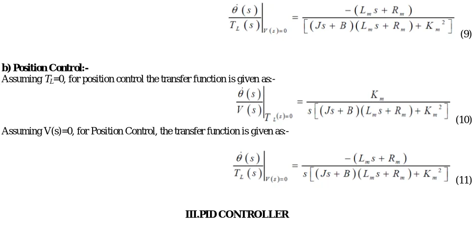
For Speed Control, the transfer function is given (from equations 6 and 7):-
(9)
b) Position Control:-
Assuming TL=0, for position control the transfer function is given as:-
(10) Assuming V(s)=0, for Position Control, the transfer function is given as:-
(11)
III.PID CONTROLLER
Different characteristics of the motor response (steady-state error, peak overshoot, rise time, etc.) are controlled by selection of the three gains that modify the PID controller dynamics.
controller computes both the derivative and the integral of this signal. Therefore, the PID controller is defined by the relationship between the controller input e and computes output u that is applied to the motor armature:
u = Kp e + Ki∫ dt + Ke (12) Where Kp- Proportional gain
Ki- Integral gain
Kd- Derivative gain.
The signal u will be sent to the plant and the new output Y will be obtained and sent back to the sensor again to find the new error signal e . The controller takes e and computes its derivative and it’s integral again. This process goes on and on. By adjusting the weighting constants Kp, Ki and Kd, the PID controller can be set to give the desired performance. Taking Laplace Transform of equation (12) gives the following transfer function:
This transfer function clearly illustrates the proportional, integral and derivative gains that make up the PID compensation.
3.1 Classical PID Tuning Methods
The PID controller is the most common general purpose controller in the today’s industries. It can be used as a single unit or it can be a part of a distributed computer control system. Over 30 years ago, PID controllers were pneumatic mechanical devices, whereas nowadays they are implemented in software based techniques like ANN, Fuzzy Logic, Genetic Algorithm and most popular Optimization techniques.
After implementing the PID controller, now we have to tune the controller; and there are different approaches to tune the PID parameters like P, I and D. The Proportional (P) part is responsible for following the desired set-point while the Integral (I) and Derivative (D) part account for the accumulation of past errors and the rate of change of error in the process or plant, respectively.
3.2 Need of Controller Tuning
Controller is very important element of process industry. The control system acts as the nervous system for the plant. It provides sensing, analysis, and control of the physical process. When a control system is at properly tuned, the process variability is reduced, efficiency is maximized, energy costs are minimized, and production rates can be increased. Controller tuning refers to the selection of tuning parameters to ensure the best response of the controller. Choose tuning that is too slow, and the response will be sluggish, the controller will not handle upsets, and it will take too long to reach set point. Choose tuning that is too aggressive, and the loop will overshoot or become unstable. So correct tuning is necessary for the controller. Tuning should be according to the need of the plant, if simple tuning works well, then should not use complex one, because that would not be cost effective. In control better and better performance always needed from time to time so always go for more accurate tuning from on – off tuning to P, I, D, PI to PID
.
IV.FUZZY LOGIC CONTROLLER
Fuzzy logic control is a control algorithm based on a linguistic control strategy, which is derived from expert knowledge into an automatic control strategy. The operation of a FLC is based on qualitative knowledge about the system being controlled .It doesn't need any difficult mathematical calculation like the others control system. While the others control system use difficult mathematical calculation to provide a model of the controlled plant, it only uses simple mathematical calculation to simulate the expert knowledge
The description of the technological process is available only in word form, not in analytical form.
It is not possible to identify the parameters of the process with precision.
The description of the process is too complex and it is more reasonable to express its description in plain language words.
The controlled technological process has a “fuzzy” character.
It is not possible to precisely define these conditions.
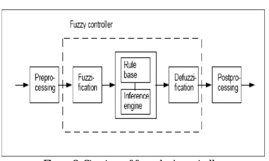
A fuzzy logic controller has four main components as shown in Figure: a) Fuzzification
b) Inference engine c) Rule base d) Defuzzification
Figure 3: Structure of fuzzy logic controller
4.1: Fuzzification
The first step in designing a fuzzy controller is to decide which state variables represent the system dynamic performance must be taken as the input signal to the controller. Fuzzy logic uses linguistic variables instead of numerical variables. The process of converting a numerical variable (real number or crisp variables) into a linguistic variable (fuzzy number) is called fuzzification. This is achieved with the different types of fuzzifiers. There are generally three types of fuzzifiers, which are used for the fuzzification process; they are
1. Singleton fuzzifier 2. Gaussian fuzzifier
3. Trapezoidal or triangular fuzzifier
4.2: Rule base
A decision making logic which is, simulating a human decision process, inters fuzzy control action from the knowledge of the control rules and linguistic variable definitions [9]. The rules are in “If Then” format and formally the If side is called the conditions and the Then side is called the conclusion. The computer is able to execute the rules and compute a control signal depending on the measured inputs error (e) and change in error (de). In a rule based controller the control strategy is stored in a more or less natural language. A rule base controller is easy to understand and easy to maintain for a non- specialist end user and an equivalent controller could be implemented using conventional techniques [14].
4.3: Inference engine
4.4: Defuzzification
The reverse of Fuzzification is called Defuzzification. The use of Fuzzy Logic Controller (FLC) produces required output in a linguistic variable (fuzzy number). According to real world requirements, the linguistic variables have to be transformed to crisp output. There are many defuzzification methods but the most common methods are as follows: 1) Center of gravity (COG)
2) Bisector of area (BOA) 3) Mean of maximum (MOM)
V.SIMULATION & RESULTS
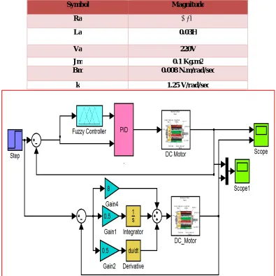
As discussed up to this point, the last objective is to model and simulate separately excited DC motor with aPID controller oriented feedback loop through MATLAB software and then use a Fuzzy logic tuned with PID controller instead of conventional PID Controller in the feedback loop of the system and compare the output motor speed responses. This objective is fulfilled with following parameter values:
Symbol Magnitude
Ra 0.7Ω
La 0.03H
Va 220V
Jm 0.1 Kg.m2 Bm 0.008 N.m/rad/sec
k 1.25 V/rad/sec
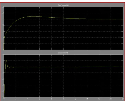
Figure 6: Output waveform of Speed Control of SEDC Motor with Fuzzy Logic Tuned PID Controller and Conventional PID Controller
.
Controller Used Rise Time (Tr)
In sec
Settling Time (Ts) In sec
Peak Response In %
Steady State
Error
Conventional PID Controller 0.7 19.4 1.23 0.2
Fuzzy Logic Tuned PID Controller
0.5 15.7 1.04 0
From these results it can be seen that Fuzzy Tuned PID controllers have better stability, small overshoot, fast response and no steady state error.
VI.CONCLUSION
REFERENCES
[1] Sukumar Das, Shubhajit Pal, Prof. Goutam Kumar Panda, Prof. Pradip Kumar Saha, “Nonlinear Dynamics Study Of Voltage Mode Controlled DC Drive With PID Controller” in Int. Journal of Engineering Research and Applications, Vol. 4, Issue 2( Version 1), pp.729-733, February 2014.
[2] Rem Langari,”Past, present and future of fuzzy control: A case for application of fuzzy logic in hierarchical control,”IEEE, pp.760-765, 1999 [3] Chuen Chien Lee, “Fuzzy logic in control systems i.e. fuzzy logic controller,”IEEE Transactions on Systems, man and cybernetics, Vol
20,No.2, March/April 1990.
[4] K. J. Astrom and T. Hagglund (1995) “PID Controllers: Theory, Design, and Tuning”, Instrument Society of America, USA, pp. 134-151. [5] J. J. D’Azzo and C. H. Houpis, Linear control system analysis and design, McGraw-Hill, New York, 1995.
[6] E. Fossas and G. Olivar, “Study of chaos in the buckconverter”, IEEE Transactions on Circuits and Systems-I:Fundamental Theory and Applications, Vol. 43, January.
[7] J. Figueroa, C. Brocart, J. Cros, and P. Viarouge,“Simplified simulation methods for polyphase brushless DC motors,” Mathematics and Computers in Simulation, vol. 63, issues 3-5, pp. 209-224, Nov. 2003.
[8] J. Santana, J. L. Naredo, F. Sandoval, I. Grout, and O. J. Argueta, “Simulation and construction of a speed control for a DC series motor,”Mechatronics, vol. 12, issues 9-10, pp. 1145-1156, Nov.-Dec. 2002.
[9] C. C. Chan and K. T. Chau, “Spectral modeling of switched-mode power converters,” IEEE Trans. Ind. Electron., vol. 41, pp. 441–450 [10] A. Biswas, S. Das, A. Abraham and S. Dasgupta, “Design of fractional-order PIλDμ controllers with an improved differential evolution,”
Journal of Engineering Applicationsof Artificial Intelligence, vol. 22, 2009, pp. 343–350.
[11] J. G. Juang, M. T. Huang and W. K. Liu, “PID control using prescribed genetic algorithms for MIMO system”, IEEE Trans. Systems, 2008. [12] Robadi, K.Nishimori, R.Nishimura, N.Ishihara, ‘Optimal feedback control design using genetic algorithm in multimachine, Electrical Power
and Energy, 2001.
[13] A.N.K.Nasir, M.A. Ahmad and M.F.Rahmat, “Performance Comparison between LQR and PID Controller for an Inverted Pendulum System”, International Conference on Power Control and Optimization, Chiang May, Thailand, July 2008.
[14] P.O.M. Scokaert and J. B. Rawlings, “Constrained linear quadratic regulation”, IEEE Trans. Automatic Control, Vol. 43, No. 8, pp.1163-1169, 1998.
[15] R. Yu, R. Hwang, ‘Optimal PID Speed Control of Brushless DC Motors using LQR Approach’, In Proc. IEEE International Conference on Man and Cybernetics, Hague, Netherlands, October 2004.
[16] Atul Kumar Dewangan, Sashai Shukla, Vinod Yadu “Speed Control of a Separately Excited DC Motor Using Fuzzy Logic Control Based on Matlab Simulation Program” International Journal of Scientific & Technology Research Volume 1, Issue 2, ISSN 2277-8616 pp. 52 – 54 ,March 2012
[17] Zadeh L. A., "Outline of a New Approach to the Analysis of Complex Systems and Decision Processes", IEEE Transactions Systems, Man and Cybernetics, SMC-3, 1973, pp. 28-44.