Closed Loop operation of Solar PV
Inverter with PI controller using dsPIC
Athira A R1, Jeyapriya C2, Kingini A G3,Remya James4 , Biju .K5 B.Tech Student, Dept. of EEE, College of Engineering, Munnar, India1
B.Tech Student, Dept. of EEE, College of Engineering, Munnar, India2
B.Tech Student, Dept. of EEE, College of Engineering, Munnar, India3
B.Tech Student, Dept. of EEE, College of Engineering, Munnar, India4
Assistant Professor, Dept. of EEE, College of Engineering, Munnar, India5
ABSTRACT: Conventional energy sources such as thermal, diesel appliances, and nuclear are difficult to generate the electricity for the presence of greenhouse emission, maintenance problem. To overcome such problems, solar energy is one of the fastest growing renewable energy sources across the globe. In recent trends, solar power generation has tremendous growth. From the sunlight the light beams will be hit on a photovoltaic cell, it emitted the electrons from n type to p-type layer and it will generate the power [1]. This project is designed to use solar energy for household loads using a single phase solar inverter with an effective feedback system using dsPIC30F2010.Single phase inverter is widely used in various application such as UPS, Renewable energy conversion, power source [2]. A solar inverter, or PV inverter, converts the direct current (DC) output of a photovoltaic solar panel into a utility frequency alternating current (AC) by a dsPIC30F2010 that can be fed into a commercial electrical grid or used by a local, off-line electrical network.
KEYWORDS:dsPIC30F2010, Feedback system
I.INTRODUCTION
The energy demand in the world is steadily increasing and new types of energy sources must be found in order to cover the future demands, since the conventional sources are about to be emptied. In recent years, the interest in solar energy has risen due to surging oil prices and environmental concern [1].
This paper aims to design, build, and test a solar panel inverter with a feedback system. The main function of the inverter is to provide an AC output voltage with less voltage distortion under both linear and nonlinear load applications[2]. AdsPIC30F2010 used for producing the PWM and providing feedback for the inverter. Thus an output voltage of 180V will be obtained at all time without any fluctuations even if the input is varying.
This transformer based inverter has the capable to block the DC voltage, and filter out the high frequency noise generated by the inverter and to increasing the output voltage range. Blocking the DC voltage is also very important for the load contained magnetic component such as inductor, and transformer. DC voltage component exist in the output of AC inverter which may cause saturation and increase the power loss of line frequency transformer[2]. The voltage feedback signal is taking from the transformer at the inverter output and uses low pass filter to separate the DC voltage, and thereby reducing the control method [2].
II.FEATURES
The key features of the system are, a constant 180V, 50Hz, sinusoidal voltage can be obtained as the output always even if the input is varying.
dsPIC30F2010 is the major part of this project which will produce PWM pulses as well as providing the feedback for getting 180V always.
III. BLOCK DIAGRAM OF THE SYSTEM
Fig1. Shows a basic schematic block diagram for solar inverter with an effective feedback system. Solar panel gives small range DC output which is converted in to PWM pulses with the help of dsPIC30F2010 which is always comparing the input voltage with a previously set reference voltage.If there is any variation in the input voltage the potential transformer will read the value and it is given to the PIC.Since it has been already programmed the input will be adjusted to get 180 V always.
Figure 1:Block diagram of closed loop solar inverter
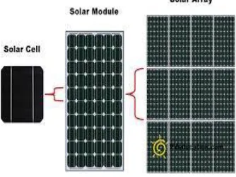
A Solar panel
Solar panel consisting of several PV cells in parallel has been used. It will give nearly 24v dc supply[3].Since the dc from the solar panel is of varying type, a battery is used for storing the solar energy. In this project the supply is given through a battery.
B.Current transformer
Current transformer will measure the input current that is to be given to the dsPIC.It will change current from one magnitude to another or to perform an isolating function, that is, to isolate the utilization current from the supply voltage for safety to both the operator and the end device in use.Also it will display the current during various inputs continuously.
C Potential transformer
Voltage transformers are most commonly used to lower the high line voltages.Potential transformer will continuously measure the voltage and display it in the monitor. Thus we can evaluate the output as well as the input of the inverter at all the time
.
DdsPIC30F2010
This is a digital signal processing (DSP) type of microprocessor family from microchip. It means in the design of the computer attention has been paid to the speed that it can process signals in real time. These units may have built in ADC and DAC so they can deal with analogue signals.dsPIC30F2010 has a modified Harvard architecture. It has a C compiler optimized instruction set architecture.dsPIC30F2010 contains 83 base instructions with flexible addressing modes. The instructions are 24-bit wide and data paths are 16-bit wide.
E H-Bridge Inverter
A common use of the H bridge is an inverter. The arrangement is sometimes known as a single-phase bridge inverter. A H bridge is an electronic circuit that enables a voltage to be applied across a load in either direction. The H bridge with a DC supply will generate a square wave voltage waveform across the load[5]. For a purely inductive load, the current waveform would be a triangle wave, with its peak depending on the inductance, switching frequency, and input voltage.
Figure 3.Circuit diagram of H Bridge inverter
B Filter
The basic function of a filter is to filter out the unwanted signals from the required pulses. Here the filter used is capacitor filter which will pass pure AC and block the DC to pass to the load [9].
C.Transformer
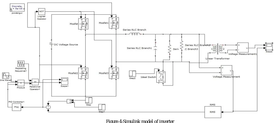
IV. SIMULLINK MODEL
The simulation is done with single phase inverter using a PI controller with dsPIC30F2010.The output is taken across the transformer which will give an output of 180V.By varying the input DC voltage the output of the solar inverter has been checked and verified the output correctly[7].
Figure 4:Simulink model of inverter
V.SIMULINK RESULTS
The simulation results of single phase solar inverter using PI controller with dsPIC has been taken from the simulink model shown above. The output has been take with 2 different input DC voltage and an output voltage of 180V is obtained in both cases .The single phase transformer based inverter for nonlinear load application using PI controller is verified with single phase rectifier load using MATLAB Software. The simulated result shows that the inverter will give constant output even if the input DC voltage is varying[2].The obtained output is as follows
VI. EXPERIMENTAL SETUP
Figure 6:Experimental setup
The experimental setup includes regulated DC power supply instead of battery.PCB board which contains dsPIC, H Bridge, CT, PT,LED’s. The proposed hardware is shown in figure 6.The circuit with dsPIC and H-Bridge inveter has been built. Transformer of 12/230 V is used. Load is an incandescent lamp of 14W.
VII.CONCLUSION
The proposed work of the single phase solar inverter with PI controller can significantly give a constant output even if the input is varying.From the simulation results of closed loop solar inveter we get the outpur AC voltage constant and get desired output from inverter.This closed loop solar inverter is low in cost,easy to install and compact in size[9].Also it ensure a very good safety to the appliances that are connected to the inverter.
REFERENCES
[1] Arun Kumar Rath,Pradipta Kumar Nayak,Ch.VenketeswaraRao,Ch.V.Suryanarayana”Design and testing of low cost solar power inverter”Volume 2, Issue 8, August 2013, ISSN 2319 – 4847.
[2]Single Phase Transformer Based Inverter For Nonlinear Load Application Using PI ControllerR. Ramesh1, A.John Dhanaseely2, P. Pughazendiran3 PGStudent1, Associate professors1, 2 IFET College of engineering, villupuram.
[3] Vimal M. Vaniya, Jaydeep G. Gajipara Prof. JayantiA.“Single phase PWM inverter with closed loop DC-DC boost Converter for solar application”Department of electricalEng.Marwadi education foundation faculty of P.G.studieRajkot-360 003 Gujarat India. Vol. 2 Issue 5, May – 2010 ISSN: 2278-0181.
[4] NishitKapadia, Amit Patel, Dinesh Kapadia ,”Simulation and Design of low cost single phase solar inverter” www.ijetae.comISSN 2250- 2459, Volume 2, Issue 1, February 2012.
[5] Fernando LessaTofoli, Julio Cesar Sconell, Carlos Alberto Gallo, Sergio Manuel Rivera Sanhuenza,” A Low CostSingle-Phase Grid-Connected PhotovoltaicSystemReduced Complexity” IEEE 978-1-4244-3370-4/09,2009.
[6] Yishu Zhao, Yan Zhang, Depeng Wang, Jie Zhan,The Circuit Topology For Single-Phase Grid Connected System And The Control Technology On Converters, IEEE Transections OnElectronicDevices,Vol 48,No.5,2001.
[7] VikasKulkarni, Rajesh Nehete “Simulation and Analysis of Photo-Voltaic (PV) based Solar Inverter System”ISSN: 2231- 2307, Volume-3, Issue-6, January 2014
[8] R. A. Messenger and J. Ventre, Photovoltaic System Engineering, CRC, 2nd ed., 2003.
[9] SlametRiyadi,TjukupMarnoto,”Design of DC to AC inverter LC filter for solar power system “Universitas Muhammadiyah,Yogyakarta,ISSN 1693-4393,7 February 2006