A Comparative Study of Different Saturation
Methods for Current Transformer
Anju C.S1, Priyalakshmi S2
Assistant Professor, Dept. of EEE, Sree Buddha College of Engineering for Women, Kerala, India1
Assistant Professor, Dept. of ECE, Sree Buddha College of Engineering for Women, Kerala, India2
ABSTRACT: Modern protective system requires a faithful reproduction of primary short circuit current. Often, especially in high power installation, an important part of the current, during a few cycles at least, is the dc component, which causes severe saturation conditions, if the current transformer is not correctly selected and employed, many models have been presented to simulate current transformer, but only some of them are well suited for transient conditions. There are many methods for saturation testing of current transformer. Here we are comparing two methods for current transformer saturation testing. First one is conventional method and the second one is advanced method i.e. using Simulink.
I.INTRODUCTION
Instrument transformers are high accuracy class electrical devices used to isolate or transform voltage or current levels. The most common usage of instrument transformers is to operate instruments or metering from high voltage or high current circuits, safely isolating secondary control circuitry from the high voltages or currents. The primary winding of the transformer is connected to the high voltage or high current circuit, and the meter or relay is connected to the secondary circuit. There are two types of instrument transformers. First one is current transformer and the other is potential transformer. Current transformer is a current measuring device. It is used to protect personal and apparatus from high current. Current transformer is an instrument transformer intended to supply measuring instruments, meters, relays and other similar apparatus. In a ct in normal conditions for the use of secondary current is substantially proportional to the primary current and differs in phase from it by an angle which is approximate zero for an appropriate direction of the connection. “Traditional” Current Transformers fall in to a general category known as instrument transformers. Their main purpose is to produce from the primary current, a proportional secondary current that can easily be measured or used to control various circuits. The primary winding is connected in series with the source current to be measured, while the secondary winding is normally connected to a meter, relay or a burden resistor to develop a low level voltage that is amplified for control purposes.
Transformers are also constrained in their performance by the magnetic flux limitations of the core. For ferromagnetic core transformers, we must be mindful of the saturation limits of the core. Remember that the ferromagnetic materials cannot support infinite magnetic flux density :they tend to saturate at a certain level, meaning that further increase in magnetic field force (mmf) do not result in proportional increases in magnetic field flux.
When a transformer primary winding is overloaded from excessive applied voltage, the core flux may reach saturation levels during peak moments of AC sine wave cycle. If this happens the voltage induced in the secondary will no longer match the wave shape as the voltage powering the primary coil. In other words the overloaded transformer will distort the wave shape from primary to secondary winding, creating harmonics in the secondary winding‘s output.. As we discussed before, harmonic component in ac power system typically cause problems. It is about normal power transformers. The following graphs show how the saturation affects normal transformer.
For a current transformer the main causes of saturation are • Asymmetry in primary side
• Secondary becomes opened.
integrated heating effect on primary fuse as a result of this in rush current is equivalent to a current having magnitude of 12 times the primary full load current of transformer core as well as the instantaneous voltage when the transformer is energized. Since these two parameters are unknown and uncontrollable, the fuse must be sized, withstand maximum in rush that occurs under worst case energization.
Now coming to second condition in which secondary seems to be opened. Opening a current transformer circuit will produce hazardous voltages, which can lead personal injury or death, property damage and economic loss. Because of this fact never place fuses with secondary circuit of a current transformer. A resistor called burden resistor is connected to secondary to limit the voltage within the exact limits.
A small part of primary current of a secondary transformer is used to excite the core. If the secondary of the transformer is open, the primary current remains the same because it is determined by the load on the power circuit and is all used to magnetize the transformer core. The core saturates, and the voltage induced on the secondary develops high voltage spikes due to the high rate of change of magnetic flux around the zero crossings of the primary current. The voltage peaks can be several KV high.
II. CONVENTIONAL METHOD
For CT saturation testing conventional methods can be used. The test for CT saturation is excitation test. When a CT is saturated, the magnetic path inside the CT operates like a short circuit on the transmission line. Almost all of the energy supplied by the primary winding is shunted away from the secondary winding and is used to create a magnetic field inside the CT. Saturated CTs can be very deceiving when used to supply protective relays as they may operate normally at low current levels and not operate at all during fault currents.
Some of the following conditions can cause CT saturation:
• CT secondary burden greater than rated.
• Extremely high current flowing through the CT (fault current). • Current flowing through CT primaries with open-circuit secondaries. • DC current flowing through either winding.
The excitation test is used to prove that the CT is not saturated and will operate within specifications at the rated burden. It is important to remember when comparing test results to the burden rating that the burden rating is a minimum value. The CT could actually have a higher rating. This happens often in transformer bushing applications.
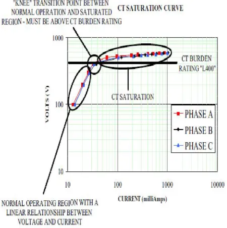
A saturation test is performed by applying ac voltage to the CT secondary and increasing the voltage in steps until the CT is in saturation. The test voltage is slowly decreased to zero to demagnetize the CT. The test results are plotted on a logarithmic graph and evaluated based on the transition period between normal operation and saturation. This transition is called the knee of the curve and is directly related to the voltage burden rating of the CT. First the CT accuracy class is obtained. Then slowly increase the voltage until saturation. (We will use 1000 milli amperes for this article, but saturation could be higher or lower depending on CT construction.) Watch the current and note the voltage where the current increase begins to increase dramatically. Note the voltage where the current reaches 1000 milliampere.
Fig 1 Excitation test connection
A. .
Fig 2 Sample excitation test results
III. CT SATURATION TEST BY USING SIMULINK
IV. DESCRIPTION OF COMPLETE SYSTEM
(a) Circuit Diagram For Simulation
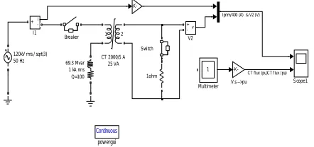
Figure 3 .Simulation circuit
(b) Circuit Description
The circuit for testing current transformer saturation using simulink is shown in Fig.3.This simulation illustrates measurement distortion and effect due to saturation of current transformer (CT). The circuit consist of a current transformer (CT) is used to measure current in a shunt inductor connected on a 120 kV network. The CT is rated 2000 A / 5 A, 25 VA. The primary winding which consists of a single turn passing through the CT toroidal core is connected in series with the shunt inductor rated 138.48 Mvar, 138.48 kV (240kV/sqrt(3)), 1 kA rms ,with quality factor of100. The secondary winding consisting of 1*2000/5 = 400 turns is short circuited through a 1 ohm load resistance. A current sensor and the gain (5/2000) connected to the primary of current transformer read the primary current and a voltage sensor connected at the secondary reads a voltage which should be proportional to the primary current.
In steady state, the current flowing in the secondary is 1000*5/2000 = 2.5 A (2.5 Vrms or 3.54 Vpeak read by the voltage measurement block V2).Open the CT dialog box and observe how the CT parameters are specified. The CT is assumed to saturate at 10 pu and a simple 2 segment saturation characteristic is used. The primary current reflected on the secondary and the voltages developed across the 1 ohm resistance are sent to trace 1 of the Scope block through a mux. The CT flux, measured by the Multimeter block is converted in pu and sent to trace 2. The value of 1 pu is given in the gain followed by the multimeter. For running this model we should place ‘powergui’ block on the simulink model.
The switch connected in series with the CT secondary is normally closed. This switch will be used later to illustrate over voltages produced when CT secondary is left open
(c) Design
The circuit design comprises the analysis and synthesis of circuit components. To design any circuit we need to be able to predict the voltages and currents at all places within the circuit. Circuit simulation software allows engineers to design circuits more efficiently, reducing the time cost and risk of error involved in building circuit. The circuit for computerized testing of current transformer saturation contains various parameters and can be designed as given below: Highest system voltage V is =240 kV
Current ratio of the current transformer =2000/5A Rated power of current transformer =12 VA Number of primary windings N1 =1 turn
No.of secondary windings N2 =N1×(I1/I2)=1×2000/5 =400 turns
Voltage rating of RL load connected to the primary of current transformer is given by VRL= 240kV/√3 = 138.48kV Current rating of RL load connected to the primary of current transformer is given byIRL=1kA (rms)
∅ = 90°
Power rating of RL load =VRL×IRL× sin∅
Continuous pow ergui v + -V2 -K-V.s -->pu Switch Scope1 1 Multimeter i + -I1 -K-1 2
CT 2000/5 A 25 VA Breaker
69.3 Mvar 1 kA rms
Q=100 1ohm
120kV rms / sqrt(3) 50 Hz
In this test, the breaker is closed at a peak of source voltage (1.25 cycles). That is we should close the switch at t=1.25/50 seconds. This switching produces no current asymmetry. Start the simulation and observe the CT primary current and secondary voltage (first face of Scope block).And the flux can be observe at second face of scope block. As expected the CT current and voltage are sinusoidal and the measurement error due to CT resistance and leakage reactance is not significant. The flux contains a DC component but it stays lower than the 10 pu saturation value.
Figure 4. Breaker is closed at a peak of source voltage (t = 1.25 cycle)
(2) CT saturation due to current asymmetry
Now, change the breaker closing time in order to close at a voltage zero crossing. Use t = 1/50 s. This switching instant will now produce full current asymmetry in the shunt reactor. Restart the simulation. Observe that for the first 3 cycles, the flux stays lower than the saturation knee point (10 pu). The CT voltage output V2 then follows the primary current.However, after 3 cycles, the flux asymmetry produced by the primary current causes CT saturation, thus producing large distortion of CT secondary voltage.
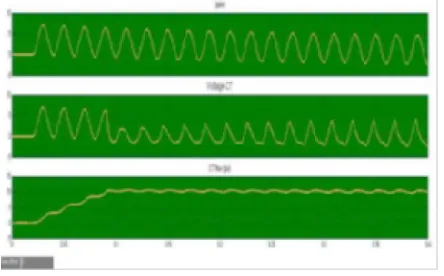
Figure 5. Breaker is closed at a peak of source voltage (t = 1 cycle)
(3) Overvoltage due to CT secondary opening
Figure 6. Overvoltage due to CT secondary opened
V. RESULT AND DISCUSSION
The working of simulation circuit can be explained in three operations.First one is the normal operating mode. The output waveform for normal operation is given in figure 4.Here primary current (Iprm) and output voltage (V2) against time are plotted. Second graph is CT flux value in pu against the same time period of above graph. Both graph are given in such a way that to compare this parameters at the same time. In normal operating mode the switching produces no current asymmetry. So the current transformer primary current and secondary voltages are sinusoidal and measurement error is not significant. The flux however contains a flux asymmetry but it stays lower than 5 pu saturation value.
Second one is current transformer saturation due to current asymmetry. This is plotted in figure 5. In this stage saturation occurs due to asymmetry in the primary of current transformer. The parameters of both graphs are same as above. But in this case the variation can observed that when the voltage starts to distort from the sine wave the flux value crosses 5 pu and corresponding variations happens that means the core is being saturated at this condition due to asymmetry in primary current. It can be observed that for the first three cycles of secondary voltage or primary current, the flux stays lower than the saturation knee point (5pu). The current transformer output voltage follows primary current. However after three half cycles, the flux asymmetry produced by primary current drives transformer into saturation, thus producing large distortion of current transformer secondary voltage. After reaching the knee point (5pu) the flux is constant.
The third one is CT saturation due to secondary opening. It is illustrated in figure 6. In this condition the saturation occurs due to opening in the secondary. In the graph 1 it can be observed that high spikes above 250 volt have been created in secondary voltage due to opening the secondary of current transformer and graph 2 shows fluctuations in flux. After saturate the current transformer core the flux wave is in the square shape and it is chopped at positive 5 and negative 5. Large dphi/dt produced at flux inversion generates high voltage spikes as shown in Fig.9.3.
VI. CONCLUSION AND FUTURE WORK
A comparative study of different saturation methods for current transformer has been done. Here we considered two method for study. Saturation testing using conventional methods and saturation tesing using Simulink. Conventional methods are time consuming and may contain errors. Saturation tesing using Simulink is an effective one. It is an accurate one. This simulation is designed in such a way that ratings and specifications of all components are variable as per the requirements; means the same simulation can be used for CT’s of any rating. So this simulation is usable until a replacement for CT is discovered.
REFERENCES
[1] PreetKhandelwal, Vijay Kumar Shukla “Current Transformer Saturation and its Impact of DC offset on Protective System”, International Journal of of Enhanced Research in Science Technology & Engineering, Vol. 2 Issue 10, October-2013