Generation of electricity by improving dual axis solar
tracker using Arduino
So
nali A.Nikam; Switi A. Mahure; Nishikant S. Pakhale; Rahul V.
Kottewar & Mayur Gawande.
Dept of Electronics and telecommunication,DBNCOET Yavatmal.
Using a range of technologies such as photovoltaic, thermal electricity and etc solar cell (also called a photovoltaic cell) is an electrical device that converts the energy of light directly into electricity by the photovoltaic effect. A solar panel is a set of solar photovoltaic modules electrically connected and mounted on a supporting structure. The majority of modules use wafer- based crystalline silicon cells or thin-film cells based on cadmium telluride or silicon. The structural member of a module can either be the top layer or the back layer. Electrical connections are made in series to achieve a desired output voltage and in parallel to provide a desired current capability. Several types of solar cells are available.silicon solar cell,thin film solar cell,multijunction solar cell and new technologies including organic solar cell.
LabVIEW (short for Laboratory Virtual Instrument Engineering Workbench) is a system-design platform and development environment for a visual programming language from National Instruments. The software is perhaps the most important component of the system. The main routine, or VI, provides a front panel interface that allows the operator to control and monitor the system. It calls to perform functions that gather analog input, send analog output.
The front panel is what allows the operator to control and monitor the process. It includes software controls and indicators that mimic physical controls such as buttons, sliders, LEDs, and charts. The block diagram is a graphical representation of the underlying software
program. It consists of icons that represent typical programming elements such as constants, variables, subroutines, and loops.
Arduino is a single-board microcontroller, intended to make the application of interactive objects or environments more accessible. It's an open- source physical computing platform and a development environment for writing software for the board. Arduino can be used to develop interactive objects, taking inputs from a variety of switches or sensors, and controlling a variety of lights, motors, and other physical outputs. Arduino has some advantages for educational and interested recreational over other systems like Inexpensive, Open source and extensible software, extensible hardware
The LabVIEW Interface for Arduino (LIFA) allows users to control sensors and acquire data through an Arduino microcontroller using the graphical programming environment LabVIEW. Arduino microcontroller acts as an I/O engine that interfaces with LabVIEW VIs through a serial connection. This helps to move information from Arduino pins to LabVIEW without adjusting the communication, synchronization. Using the common Open, Read/Write, Close convention in LabVIEW, we can access the digital, analog, pulse-width-modulated, I2C, and SPI signals of the Arduino microcontroller. The LabVIEW software package from National Instruments is used to develop the custom data acquisition.
SOLAR TRACKER
Sunlight has two components, the direct beam that carries about 90% of the solar energy, and the diffuse sunlight that carries the remainder. The diffuse portion is the blue sky on a clear day and increases proportionately on cloudy days. As the majority of the energy is in the direct beam, maximizing collection requires the sun to be visible to the panels as long as possible. A typical solar panel converts only 30 to 40 percent of the incident solar irradiation into electrical energy.
.
Figure 1: Block diagram of the
system
This paper proposes the use of dual-axis solar tracker. The paper continues with specific design methodologies pertaining to Light Dependent Resistor (LDR), DC motors, solar panel, load sensor, solar map and a software .There also tracker which uses solar map in cloudy days. Depending on the location, Solar map gives information on where the sun is at different time of day throughout the year.. Also we are using the load sensor which is use to detect that snow that may accumulate on the solar panel which may reduce the efficiency of the panel to track the sun. If there is a snow on our panel then the arduino will record the change in a weight of the panel .Then it will give indication to the motor driver to turn the panel in a vertical angle then it
will remains at that position for 30 seconds and comes in its actual position. One of the thing which make advantageous the solar panel other than traditional solar panel is that here instead of using the traditional solar cell we can use here the multijunction solar cell..But it must be noted that the price of the MJ solar cell is very hgh.because in the construction of the multijunction solar cell we are using the materials for doping which have high prices .Also the construction of the MJ solar cell is very complex so the price of the is get increasing. But if we think besides the price then it can be noted that MJ solar cell have 40% more efficiency than traditional solar cell. Also it produce power about 476 W/m2.In MJ solar cell we have to use different metals which ar0e layered above each other. The dual-axis tracker is a very compatible system to be developed with the usage of LabVIEW Interface for Arduino. The controller received an analog input from the Light Dependent Resistor (LDR) and converts it into digital signal by Analog-to-Digital converter. The program is designed in the environment of LabVIEW. The output given to the DC motor will determine the movement of the solar panel.
The weight of the solar panel 80 lb , our panel should turn in fully 3600 angle and it should be tilt 800 with horizontal.
METHODOLOGY
very high, sometimes as high as 1000 000 ohms, but when they are illuminated with light resistance drops dramatically. LDR’s have low cost and simple structure.
A DC motor relies on the fact that like magnet poles repels and unlike magnetic poles attracts each other. DC motors consist of one set of coils, called armature winding, inside another set of coils or a set of permanent magnets, called the stator. Applying a voltage to the coils produces a torque in the armature, resulting in motion. DC motor with gear arrangement have been selected since they are cheaper than servo and stepper motors .L293D IC having two channels has been used to drive the DC motors. DC motors with gear arrangement have been used to achieve the desired speed in moving the solar panel .The most important effect of using DC motor with gear mechanism in dual axis tracking system is getting mechanical stability of solar panel without spending much power for DC motors .The Dc motors can turn either clockwise or anticlockwise direction depending upon the sequence of the logic signals. The sequence of the logic signals depends on the difference of light intensity of the LDR sensors. To rotate the DC motor dual slewing driver is used which provides it a rotational torque.
The principle of the solar tracking system is done by Light Dependant Resistor (LDR). Four LDR’s are connected to Arduino analog pin AO to A4 that acts as the input for the system.
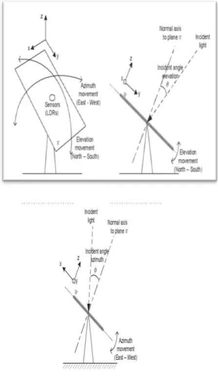
The digital controller (a software) receives the signal and then activates, with a programmable frequency, through an interface connected to the parallel port (LPT), a rotating device (actuators) with two degrees of freedom composed by two axes, each one with an independent stepper motor which control rotation around its axis. The actuators orient the plane holding the four sensors, locating it perpendicularly to the incident sun rays (Fig. 4.), then the tracking of the angular trajectory of the sun occurs.
The initial design for the solar tracker included rechargeable battery using the energy collected from the solar panel to power the tracker .Making the solar tracker would be totally self sufficient . But after practical application it is noted that rechargeable battery would not suit the application. The rason for this being that the tracker would mostly be used by plugging into wall outlet.This meant that 120v 60Hz sin wave have to step down and rectified to certain DC supply voltage which will operate the tracker.12v power supply is required to move the actuator.
Figure
2:Movement
of
plane
They are integrated at the base which supports the photovoltaic modules (Photovoltaic Panels) they allow the tracking performance to take place. Each one is composed by a mechanical structure and a motor. This system allows for the rising and azimuth movements, up to 90º and 180º respectively, to take place, using stepper motors, one for each axis. A set of reducing gears is responsible for reducing the speed of the tracker and for increasing torque as well. To decrease electricity requirements a counterweight was set so as to use potential energy in the movement.
The built-in Analog-to-Digital Converter will convert the analog value of LDR and convert it into digital. The inputs are from analog value of LDR, Arduino as the controller and the DC motor will be the output. LDR1 and LDR2, LDR3 and LDR4 are taken as pair .If one of the LDR in a pair gets more light intensity than the other, a difference will occur on node voltages sent to the respective Arduino channel to take necessary action. The DC motor will move the solar panel to the position of the high intensity LDR that was in the programming.
Control Algorithm the of the solar tracking system has been carried out through a program. This program follows a control routine of programmable frequency ll (adjustable by the user) in the control algorithm of the system. The tracking is carried out by direct solar radiation. Thecontrol program reads the corresponding bit sequence and generates pulses with delay between each one of them which are sent to the motors to perform the necessary movements, so as to locate the solar panels in perpendicular position to the Sunbeam. The logic of control allows the tracker to know when it is at the end of its trajectory, considering the number of steps taken by each one of the axis. Besides it sets limits to the movements of the panels establishing the maximum inclination, for the Azimuth movement (180º) and for the rising movement (90º)
At the end of the day the tracker sets itself in the position (0,0) called sleeping mode, in which the solar tracker offer less resistance to the winds. The solar tracker is in position (0,0) when the luminous plane is in the horizontal position. At dawn (in a real situation) it returns to the East and starts its routine all over again. Moreover the program is also equipped with a security button which allows the user to locate the tracker in the position (0,0) in case of emergency.
Algorithm had been constructed using LabVIEW programming. The algorithm of the program is given as steps in the following. Step 1.Read all analog voltages from analog channels Step 2.If all voltages are equal then motor will be in stop position. Step 3.If LDR1>LDR2 Then the top motor will rotate clockwise. Step 4.If LDR1<LDR2 Then the top motor will rotate anticlockwise. Step 5. If LDR3>LDR4 Then the down motor will rotate clockwise. We can use the solar tracking system mainly for military purposes .We can plant their solar planer for generating the electricity also the generated electricity can be used for their weapons.Also it can be used for all household application.
Figure: Picture of lab test
To confirm that , tracker would capable of following trajectory of sun we have done the lab test as shown in figure.
ADVANTAGES
Solar tracker generates more electricity than their stationary counter parts due to an increase direct exposure to solar rays.
It produces about 40% more power than optimally aligned fixed frame system.
Because it can tilt on both azimuth and zenith axis.
RESULT
By using solar tracker we can fall maximum light intensity on the solar panel hence generating more energy than typical panel.
CONCLUSION
We presented means of tracking the sun’s position with the help of arduino. Especially , it demonstrate for positioning a solar panel at point of
maximum light intensity Solar tracking system is more efficient than ordinary panel.
It is possible to reduce the energy crisis to some large extent.Instead of using single junction solar cell we can use here multi junction solar cell.
REFERENCES
[1]] Gary W. Johnson, Richard Jennings, “LabVIEW Graphical Programming”, 4th ed. McGraw-Hill.
[2] Cor J. Kalkman “LabVIEW : A software system for data acquisition, data analysis and instrument control” Journal of Clinical Monitoring and Computing, 2005, P.51-58
[3] Zolkapli, M,AI-Junid S. A. , Othman Z,Manut, , Mohd Zulkifli M.” High- Efficiency Dual-Axis Solar Tracking
Developement using Arduino”, 2013 International Conference on Technology, Informatics, Management, Engineering & Environment (TIME-E 2013) Bandung, Indonesia, June 23-26,2013
[4]M.A. Zakaria, A.F. Ayob and W.B. Wan Nik,” Characterization of Photo Voltaic Based on LabView Monitoring using Data Acquisition System at Universiti Malaysia Terengganu” UMT 11th International Annual Symposium on Sustainability Science and Management 09th – 11th July 2012, Terengganu, Malaysia
[5] Dipti Bawa, C.Y. Patil,” Fuzzy control based solar tracker using Arduino Uno” International Journal of Engineering and Innovative Technology (IJEIT) Volume 2, Issue 12, June 2013
WASE International Conference on Information Engineering, 2010.
[7]p.Roth et al.,cheap two axis sun following device energy conversion and management 46(2005)1179-1192
[8]Mehlere,e.d,P.L.Zervas,H.Sarimveis,J.A.Paly vos,and N.C.Markatos .”Determination of optimul tilt angle and orientation for solar photovoltaic arrays.”Renewable energy.35.11(2010):2468-475.
[9]Reda , Ibrahim , and Afshin Andreas . Solar position algorithm for solar radiation application . Tech . N.p.:National renewable energy laboratories,n.d.
[10]The effect of using sun tracking system on the voltage-current characterestics and power generation of flat plate photo voltaics Salah Abdallah.
[11] M.K.D.Ulaganathan, C.Saravanan, Olivia Ramya Chitranjan,” Cost-effective Perturb and Observe MPPT Method using Arduino Microcontroller for a Standalone Photo Voltaic System” International Journal of Engineering Trends and Technology (IJETT) – Vo
[12] B. C. Kuo, Sistemas de Control Automático, 7th. Edition, México: Prentice Hall Inc., 1996, p.17.
[13] F. Duarte, P. Dinis, and L. Carrilho "Two axis solar tracker based on solar maps, controlled by a low-power microcontroller" presented at the International Conference on Renewable Energies and Power Quality, 2010.
[14] H. Mousazadeh, et al., "A review of principle and sun-tracking methods for maximizing solar systems output," Renewable and Sustainable Energy Reviews, vol. 13, pp. 1800-1818, 2009.
[15] H. Arbab, et al., "A computer tracking system of solar dish with two axis degree freedoms based on picture processing of bar shadow," Renewable Energy, vol. 34, pp. 1114-1118, 2009.
[16] K. Ogata, Sistemas de Control en Tiempo Discreto, 2nd. Edition, México: Prentice Hall Inc., 1996, p.5.
[17] N. A. Kelly and T. L. Gibson, "Improved photovoltaic energy output for cloudy conditions with a solar tracking system", Solar Energy, Vol. 83, pp 2092-2102, Nov. 2009
[18] P. Roth, et al., "Design and construction of a system for suntracking," Renewable Energy, vol. 29, pp. 393-402, 2004.
[19] S. Abdallah and S. Nijmeh, "Two axes sun tracking system with PLC control", Energy Conversion and Management, Vol. 45, pp 1931- 1939,July 2004.