ISSN (Print) : 2320 – 3765 ISSN (Online): 2278 – 8875
I
nternational
J
ournal of
A
dvanced
R
esearch in
E
lectrical,
E
lectronics and
I
nstrumentation
E
ngineering
(An ISO 3297: 2007 Certified Organization) Vol. 4, Issue 10, October 2015
Generation of Power from Bicycle Pedal
B.Sneha
1, Dr.M.Damodar Reddy
21PG student [PSOC], Dept. of EEE, SV University, Tirupati, A.P, India
2Professor, Dept. of EEE, SV University, Tirupati, A.P, India
ABSTRACT: It is known that the supply of fossil fuels are scarce and their usage as energy source cause environmental degradation ,in addition to this as the world population increases the energy demand is also increasing day by day,so we are in a search of new renewable energy sources.In this paper an easy way of generating power at small levels by using bicycle pedal was analysed. Dynamo attached to the cycle pedal can serves as a mechanism for converting mechanical energy from pedal to electrical energy .For running of appliances we need to convert this dc power to ac power by using inverter.Output of the dynamo or generator depends on the pedaling speed. A hardware prototype of this model is developed and tested for various loads.
KEYWORDS: ynamo,bicycle,inverter,LM317 charger circuit
I. INTRODUCTION
India is the second most populous country in the world.With ongrowing population the needs of people and their usage is also growing,in such cases demand of electricity is very high here.Biomass and other non –commercial fuels constitute around 40% of energy requirements in India.Around 85.49% of the Indian villages are electrified [1] ,but many of the remote villages are still without electricity. People in villages mainly use bicycle as their means of transport for small distances,in such places our system is of great use.Energy produced by pedaling can be used for driving small appliances.Charging of batteries can be done easily by connecting battery to the output of dynamo which is connected to pedal of bicycle. This project is meant to allow anybody to interact with a power producing mechanism, and ultimately to see how simple steps can be taken to lower our carbon footprints in environment and also helps in lowering their energy bills. World is a store house of energy ,also energy can neither be created nor be destroyed but can be transformed from one form to another .But we are not using resources effectively as if they are limited.
Humans are able to generate around 100 watts of power while bicycle riding.However this power is wasting without our knowledge,but if we make use of this we can able to power many electronic gadgets.A dynamo or alternator can be used for harvesting the energy generated by a cycler while riding.Small devices ,laptops, mobiles can be charged with this power.This mechanism can also be used with bikes,cars and exercise vehicles also [2].In cities exercise bikes are used for health purpose ,if we adopt this mechanism to such bikes it will have double advantage .Riding bicycle is a good exercise as well as good source of power. The user will be helping to stay fit too.The typical adult will burn around 300 to 700 calories for a 30 minute workout.Plus the amount of energy created over the time is surprising. In recent times this idea was being used by students in London universities, where the distance between hostel and class rooms was up to 5kms.Some students go to classes by bicycle using this mechanism to power their laptops , mobiles without going it waste.
II. WHY PEDAL POWER
Electricity was the basic need of all people,the consumption rate was increasing at 10 % every year but there has been no sufficient growth in production rate which leads to load shedding and increase in price levels [3].While pedal power is not a new concept but it has not been successfully used on a wider scale.A pedal power generator with a lighting system was developed for residential schools in India and tested, it is giving 40 minutes of lighting for 10 minute of pedaling ,this will be of a great use in populous country like India.Currently about 10 such lighting systems are in all over India and more are being undertaken.In such huge demand it will be of great help to use this technology to fed small loads.
III. BLOCK DIAGRAM
Fig 1:Block diagram of the model
Bicycle pedal is connected to the rotor of the generator ,as we goes on pedaling rotor also rotates thus producing dc power.We need to regulate this dc power to suits for conversion purpose,.regulated dc is given to inverter for conversion to ac.
Fig 2: Pedal power mechanism
IV. SYSTEM ANALYSIS IN DETAIL The first step is to select the generator type which suits this model.
A.GENERATOR
Permanent magnet synchronous generator is the best suited one for this mechanism.Synchronous generators are a major source of commercial electrical energy,they are mostly used to convert mechanical input from wind turbines to electrical energy.
A permanent magnet synchronous generator is a generator where the excitation field is provided by the permanent magnet instead of a coil[4].Here the rotor contains the magnet and the stator is a stationary armature connected to load.Magnetic field is generated through a shaft mounted permanent magnet mechanism and current is induced into armature.The magnitude of the voltage depends on the magnetic field strength and rotational speed of generator.Generator which is used in proposed system was a 100 Watts 3/4 belt drive pedal power dynamo.Back wheel of the bicycle is disconnected with chain meachanism,and pedal chain is connected to rotor of the generator with the help of metal rod welding.On the rotation of pedal ,rotor also rotates with high speed thus producing proper output[5].
Power levels produced
ISSN (Print) : 2320 – 3765 ISSN (Online): 2278 – 8875
I
nternational
J
ournal of
A
dvanced
R
esearch in
E
lectrical,
E
lectronics and
I
nstrumentation
E
ngineering
(An ISO 3297: 2007 Certified Organization) Vol. 4, Issue 10, October 2015
Power levels of the person directly related to the environment of the person pedaling.To be able to continue pedaling over an extended period the temperature of the person must be kept cool because the ambient temperature is low enough.
B.CHARGER CIRCUIT
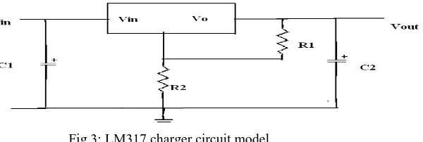
The output of the generator is unregulated dc voltage, we need to regulate this voltage for storage or for conversion purpose.Most of the batteries and inverters works with 12v regulated dc,so we need to convert generator output to a proper 12v dc.For this purpose LM317 charger circuit is used in this system.It is a dc to dc converter circuit with variable input and fixed output .
The general block diagram of the LM317 circuit is as below
Fig 3: LM317 charger circuit model
LM317 is a step down coverter meaning that it can take a range of input voltages and convert that into a stable output dc voltage that is lower than the input voltage.The chip can handle an input voltage between 15 volts to 40 volts dc and will output to 12v dc.
In this circuit R1 is a variable resistor by adjusting R1 to a proper value we can get required output.
1
2 2
1.25(1
in)
out
R V
V
IR
R
C. INVERTER
Next step is to convert from 12 vdc to 230 v ac for this there is a need to design an inverter which best suits this model
Fig 4: Inverter block diagram
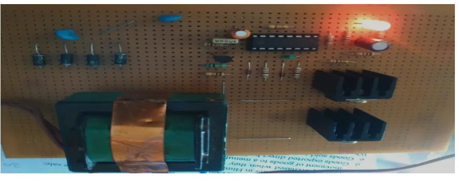
Fig 5: Inverter hardware kit
In the design some basic electronic components are employed.In generating frequency of 50 Hz an integrated circuit KA3525A in conjunction with resistors and capacitors were used to achieve an astable multivibrator circuit.The selection of resistors is to generate a high current from the IC.Capacitors are carefully selected considering the frequency of pulse in question.
KA3525A is a monolithic integrated circuit that includes all of the control circuits necessary for a pulse width modulating regulator.There are a voltage reference ,error amplifier,a pulse width modulator,an oscillator,a soft start circuit and the output driver in the chip
Inbuilt oscillator and frequency range of IC is 100hz to 500khz .Frequency of oscillation is given by
1
(0.7
3
)
T T D
f
C
R
R
KA3525 IC is a 16 pin dip ,where two outputs of the chip are fed to the two parallel field effect transistors PHP54NO6T.The FETs are screwed to heat sinks to avoid heat dissipation.Also adequate care was taken during the connection and soldering of components.
The output of PHP54NO6T was given to the primary winding of transformer and 230 v ac is obtained at the secondary side.Only one winding is activated at a time and both are energized in opposite directions.Transformer is designed to operate for 50 watts.
V .HARDWARE RESULTS
Hardware results are tested and analysed for various small loads.For continous pedaling led bulb of higher rating is powering continuously .For CFL it is taking some starting time upto 10 minutes to give power because CFL has high starting current and it will take some time to reach that current after the start of pedaling.
A battery can also be used for storage purpose ,depending on the rating of the battery it is taking time for full charge.For 2 amphere hours battery it is taking nearly 20-30 minutes for full charging.This system can be better used with exercise bicycles along with storage.
ISSN (Print) : 2320 – 3765 ISSN (Online): 2278 – 8875
I
nternational
J
ournal of
A
dvanced
R
esearch in
E
lectrical,
E
lectronics and
I
nstrumentation
E
ngineering
(An ISO 3297: 2007 Certified Organization) Vol. 4, Issue 10, October 2015
TABLE I
Below table shows the amount of voltage values produced at different speeds of the pedlar.Readings are taken for continous input with the help of multimeter.
For analyzing the input –output characteristics of the system plot a graph by taking speed on x-axis and voltage in y-axis.
Fig 6: Speed vs voltage grapgh
The above graph indicates that the on increase in speed voltage level increases ,depends on the speed of the pedlar voltage produce vary. Speed power output of the permanent magnet synchronous generator is linear.
TABLE II
The below is the tabular column of current values produced at different speed levels of pedlar.
Inorder to know the current characteristics plot a graph by taking speed on x-axis and current on y-axis
RPMS OF ROTOR
VOLTAGE
1000 9.1
1500 14.2
2500 17
3200 23.5
5000 37
ROTOR SPEED(RPM)
CURRENT(A)
1000 0.58
1500 0.8
2500 1.2
3200 1.8
Fig 7: SPEED VS CURRENT GRAPH
From the above graph it can be concluded that current values also increasing linearly with speed,at higher speed this increase is also high.For running of many loads current is the major factor, with continous input only we can achieve high current values.
Working of kit is tested with various loads and with continuous input it is better giving supply to CFL load
VI. CONCLUSION
At a time when energy crisis casting its shadow all over the world,one has to look into alternative renewable energy resources.One such alternative way of generating power is presented in this paper .The rotating energy of the pedal of the bicycle can be used to generate power at small levels.It is a useful machine where there is lack of power ,also the cost is very low.Easy to maintain and make.Moreover it is a good exercise of pedaling which makes us fit.There is a lot of future scope to extend this model to bikes and other vehicles like cars, already some prototype models with cars were being developed to extend this concept on a wider scale
REFERENCES
[1] Michael Mazga Ronnie Sabavalla, Ravi Kuchimanchi,”Pedal Powered electricity Generator” pp-2-7, July 2010.
[2] Rajesh Kannan, Meggalingam, Pranay Sreedhara, Vriliyara, Raghavendra Murali Prabhu, Rocky Katoh, “Pedal Powered Generation ,“ International journal of Applied Engineering Research, ISSN 0973-4562 VOL.7 No.11, 2012.
[3] Bradly Pelz and Jefferey Feiereisen, “Bicycle Powered Generator for the University farm” Thesis pp-8-22
[4] Chetan Khemraj, Jitendra Kumar, Sumit Kumar and Vibhav Kausik, “Energy Generation And Storage Using Bicycle Pedal System” Special Issue of International Journal of Sustainable Development and Green Economics (IJSDGE) ISSN No: 2315-4721, V-2, I-1,2013.