WIDEBAND STAR-SHAPED MICROSTRIP PATCH ANTENNA
M. Abbaspour and H. R. Hassani
Electrical Engineering Department Shahed University
Tehran, Iran
Abstract—A new wideband and small size star shaped patch antenna fed capacitively by a small diamond shape patch is proposed.To enhance the impedance bandwidth, posts are incorporated under the patch antenna.HFSS high frequency simulator is employed to analyze the proposed antenna and simulated results on the return loss, the E-and H-plane radiation patterns E-and Gain of the proposed antenna are presented at various frequencies.The antenna is able to achieve in the range of 4–8.8 GHz an impedance bandwidth of 81% for return loss of less than−10 dB.
1. INTRODUCTION
is to use shorting posts between the patch and the ground plane. The performance of such structures depend on parameters such as the number of the posts used, the radius of each post and the height of the posts (the thickness of the substrate) [10].In [11], a star shaped microstrip patch with corners shaped and fed by a rectangular patch showed a bandwidth of around 63%.
In this paper, a wideband microstrip antenna in the shape of a novel star shaped patch loaded with shorting posts and capacitive fed by a small diamond shaped patch is presented.The dimension of the patch and the parameters of the shorting posts are optimized to obtain an efficient design leading to the highest possible impedance bandwidth in the range of 4 to 8.8 GHz, i.e., 81% of the centre frequency.
2. ANTENNA GEOMETRY
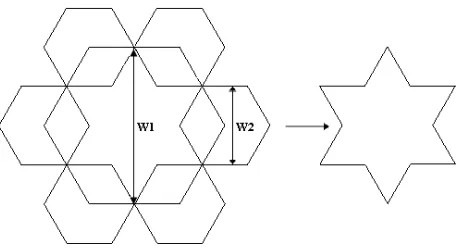
Figure 1 shows the process of building the new star shaped patch antenna.The proposed antenna shape is based on a hexagonal patch in which 6 smaller hexagonal are cut from the edges.To increase the bandwidth of the antenna four shorting posts are added under the patch.The antenna is capacitive fed by a diamond shape patch that is connected to a coaxial feed.Fig.2 shows the geometry of the complete antenna.
The star-shaped patch is separated from the ground plane with an air-filled substrate.The specification of the proposed antenna is present in Table 1.
Figure 2. Geometry of proposed antenna with the diamond shaped feed patch.
Table 1. Specification of the proposed antenna in mm.
W1 W2 P H X X1 X2 Y1 Y2 R
23.5 11.5 5 8 5.7 4.5 2 4 8 1.5
3. RESULTS
The antenna performance has been investigated through simulation via a Finite Element program, HFSS.The simulated result for the return loss is shown in Fig.3. Based on a−10 dB return loss, 81% impedance bandwidth (in the frequency range of 4 to 8.8 GHz) is obtained.
It has to be mentioned that various shapes of the feed patch were used (circular, rectangular ...) but through simulation it was found that the present diamond shape patch gives the best impedance bandwidth result.
Through simulation it has been noticed that two of the most important parameters that affects the bandwidth performance of the antenna areW1, the star shaped patch diameter, andR, the diameter of the posts.Small variations on the rest of the parameters of the antenna do not significantly affect the antenna performance.Variation of return loss against slight changes onW1 from 22 to 23 mm is shown in Fig.4. It is noticed that the highest bandwidth is achievable when
W1 is equal to 22 mm leading to 81% impedance bandwidth.
From this figure it is obvious that without posts, we have 23% of bandwidth.When the posts are added to the structure, the percentage of bandwidth increases.For diameter of the posts,R, equal to 1.5 mm
Figure 3. Return loss of the proposed antenna. W1 = 22 mm,
W2 = 11.5 mm, P = 5 mm, H = 8 mm, X = 5.7 mm, X1 = 4.5 mm,
X2 = 2 mm,Y1 = 4 mm,Y2 = 8 mm and R= 1.5 mm.
Figure 4. The Return loss of the antenna for various values of patch diameter, W1. W2 = 11.5 mm, P = 5 mm, H = 8 mm, X = 5.7 mm,
the bandwidth is 81%, while for diameter of 1 mm the bandwidth reduces to 73%.
To confirm the simulation results of Fig.3 which where obtained through HFSS method, a second powerful computer package of CST
Figure 5. Return Loss of the antenna for various diameters of the posts. W1 = 22 mm, W2 = 11.5 mm, P = 5 mm, H = 8 mm,
X= 5.7 mm,X1 = 4.5 mm,X2 = 2 mm,Y1 = 4 mm, Y2 = 8 mm.
Figure 6. Comparison of the S11 obtained through HFSS and CST.
W1 = 22 mm, W2 = 11.5 mm, P = 5 mm, H = 8 mm, X = 5.7 mm,
(b) (a)
(c)
has also been used.Fig.6 shows the comparison of S11 of this antenna with HFSS and CST.
For the structure shown in Fig.2, the simulation of the radiation pattern over the frequency range of 4 to 8.8 GHz has also been done. Fig.7 Shows the simulated E- and H-plane patterns at 4, 6 and 8 GHz including both Co- and Cross-polarizations.
Figure 8. Gain of the proposed antenna at various frequencies.
Figure 8 shows the antenna gain over the entire frequency range from 4 GHz to 10 GHz.
4. CONCLUSION
A novel wideband and small size star-shaped microstrip antenna including simple feed structure is presented.The proposed antenna has a 81% bandwidth over the frequencies 4–8.8 GHz. It has good cross polarization level and uniform H-plane pattern over the wireless communication band.It has more bandwidth and has a smaller surface area than similar designs reported in the literature.
REFERENCES
1.Wong, K.L.,Compact and Broadband Microstrip Antennas, John Wiley & Sons, 0-471-22111-2 (Electronic), 2002.
3. Eldek, A.A., A.Z.Elsherbeni, and C.E.Smith, “Characteristics of BOW-TIE slot antenna with tapered tuning stubs for wideband operation,”Progress In Electromagnetics Research, PIER 49, 53– 69, 2004.
4. Ang, B.K.and B.K.Chung, “A wideband microstrip patch antenna for 5–6 GHZ wireless communication,” Progress In Electromagnetics Research, PIER 75, 397–407, 2007.
5.Waterhouse, R. B., “Broadband stacked shorted patch,”
Electronic Letters, Vol.35, 98–100, Jan.21, 1999.
6. Ge, Y., K.P.Esselle, and T.S.Bird, “A broadband E-shaped patch antenna with a microstrip compatible feed,” Microwave &
Opt. Tech. Letter, Vol.42, No.2, July 20, 2004.
7.Wong, K.L.and Y.F.Lin, “Microstrip-line-fed compact broadband circular microstrip antenna with chip resistor loading,”
Microwave Opt. Techno. Lett., Vol.17, 53–55, Jan.1998.
8. Chen, K., X.Chen, and K.Huang, “A novel microstrip dipole antenna with wideband and end-fire properties,” Journal of Electromagnetic. Waves and Applications, Vol.21, No.12, 1679– 1688, 2007.
9.Ayoub, A.F.A., “Analysis of rectangular microstrip antennas with air substrates,” Journal of Electromagnetic Waves and Applications, Vol.17, No.12, 1755–1766, 2003.
10.Mohamed, S., “Effect of the shorting posts on short circuit microstrip antenna,”IEEE Trans. Ant. &Prop., 794–797, 1999. 11. Mirzapour, B.and H.R.Hassani, “Wideband and small size