ISSN (Print) : 2320 – 3765 ISSN (Online): 2278 – 8875
I
nternational
J
ournal of
A
dvanced
R
esearch in
E
lectrical,
E
lectronics and
I
nstrumentation
E
ngineering
(A High Impact Factor, Monthly, Peer Reviewed Journal)
Website: www.ijareeie.com
Vol. 7, Issue 5, May 2018
Design, Operation and Flexible Control of a
D-STATCOM Operating in Voltage Control
Mode
Vishal.M.Joshi 1, Pankaj J Bhakre2, K.Chandra Obula Reddy3
PG Student [EPS], Dept. of EE, MSS’s College of Engineering and Technology, Jalna (Maharashtra), India1 Professor, Dept. of EE, MSS’s College of Engineering and Technology, Jalna (Maharashtra), India2 Professor, Dept. of EE, MSS’s College of Engineering and Technology, Jalna (Maharashtra), India3
ABSTRACT: This paper presents the operating principles of a distribution static compensator (D-STATCOM) that is used to maintain the voltage of a distribution bus. A three-phase, four-wire distribution system is assumed in this study. A detailed analysis of the voltage regulation capability of D-STATCOM under various feeder impedances & design procedure to compute the value of external inductor is presented. A distribution static compensator (D-STATCOM) that can be operated flexibly in the voltage or current control mode. The objectives of this paper is To provide a detailed design procedure for selecting the external inductorregulate load voltage reduce the current, requirement reduce the system losses Switching control scheme is proposed, and its suitability is proved for this problem. The proposed scheme is verified using MATLAB Simulation results.
KEYWORDS:D-STATCOM, Voltage regulation, load voltage generation, voltage control mode
I. INTRODUCTION
Generally Static VAR Compensator is used for Load voltage regulation , reactive power compensation and for improvement of transient stability. But SVC having some limitations at the time of performance like harmonic current injection in the system, harmonic amplification and possible resonance with source impedance. This power quality problem may disturb the system that’s why a new solution is introduce to overcome this limitation is A D-STATCOM[1]. A D-STATCOM is one of most effective and Cheapest solution for the Load Voltage Regulation. It regulates the Load Voltage by supplying fundamental reactive current into the source[2]. The voltage regulation performance of D-STATCOM mainly depends upon the feeder impedance and the number of sensitive loads. For voltage control mode (VCM) operation of D-STATCOM and grid connected Inverters, the idea of inserting an external inductor in line has been reported. However, in these schemes, only the concept has been introduced leaving ample scope for further investigation and insight into the design details. D-STATCOM to regulate load voltage in stiff as well as resistive feeder, reduce the current requirement for mitigation of sag, and reduce the system losses. This scheme ensures unity power factor (UPF) operation during normal operation and maintains load voltage constant during voltage disturbances [3].
ISSN (Print) : 2320 – 3765 ISSN (Online): 2278 – 8875
I
nternational
J
ournal of
A
dvanced
R
esearch in
E
lectrical,
E
lectronics and
I
nstrumentation
E
ngineering
(A High Impact Factor, Monthly, Peer Reviewed Journal)
Website: www.ijareeie.com
Vol. 7, Issue 5, May 2018
Mithulananthan, “VAR planning with tuning of STATCOM in a DG integrated industrial system,”[6].they focus on Reactive power compensation by using tuning STATCOM in a DG integrated industrial system”.'S. Karanki, N. Geddada, Mahesh K. Mishra, and B. Kumar[6], “A DSTATCOM topology with reduced dc-link voltage rating for load compensation with nonstiff source,” IEEE Trans. Power Electron”[7] focus of this paper is on load voltage regulation and reactive power compensation of non-stiff nature distribution system. ”'M. Aredes, J. Hafner, and K. Heumann “ [8] .Three-phase four-wire shunt active filter control strategies,” IEEE Trans. Power Electron.,.” objectives of this paper to design the 3 phase 4 wire shunt active filter having 6 IGBT switches for load voltage control strategy”.'B. Singh, K. Al-Haddad, and A. Chandra, “A new control approach to three-phase active filter for harmonics and reactive power compensation,” IEEE Trans. Powe Sys., [9]'.” this paper focus on harmonic current compensation and reactive power compensation”.'H. Fujita and H. Akagi, “Voltage-regulation performance of a shunt active filter intended for installation on a power distribution system,” IEEE Trans. Power Electron.,[10].”they installed shunt active filter on power distribution system for improve the voltage regulation performance”.' R. Gupta, A. Ghosh, and A. Joshi, “Performance comparison of VSCbased shunt and series compensators used for load voltage control in distribution systems,” IEEE Trans. Power Del.,[11] , Jan. 2011'.“they brifly discuss about the voltage source controlled shunt active filter and series active filter for load voltage regulation”.'ahesh K. Mishra, A. Ghosh, and A. Joshi, “Operation of a DSTATCOM in voltage control mode,” IEEE Trans. Power [12]' operation of distributed static compensator in voltage mode depending up on nature of system is discuss in this paper”.
The organizationof this paper is as: Section Idescribes introduction of D-STATCOM,its operation and necessity of it for the load voltage regulation and reactive power compensation. Section II deals with Methodology, D-STATCOM in power distribution system, Flexible control strategy , Computation of Exact value of External Inductor for Load voltage regulation, Value of fundamental current to mitigate the SAG and MATLAB simulation for Design of External inductor to improve the performance of D-STATCOM operated in voltage control mode.Section III conclude that Design of external inductor improves the performance of D-STATCOM operated in voltage control mode.
II. METHODOLOGY 2.1 DSTATCOM in Power Distribution System
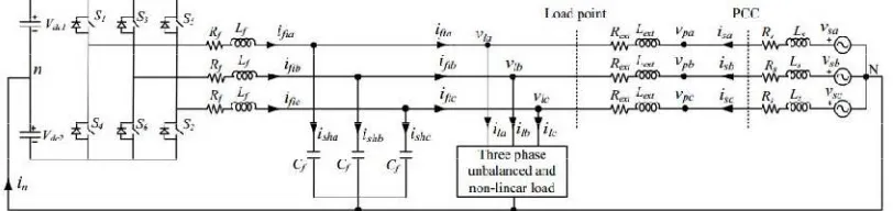
Fig. shows power circuit diagram of the D-STATCOM topology connected in distribution system. Lsand Rsare source inductance and resistance, respectively. This inductor helps DSTATCOM to achieve load voltage regulation capabilityeven in worst grid conditions[6]], i.e., resistive or stiff grid. From IEEE-519 standard, point of common coupling (PCC) should be the point which is accessible to both the utility and the customer for direct measurement. The D-STATCOMis connected at the point where load and Lextare connected. The D-STATCOM uses a three-phase four-wire VSI..Voltages across dc capacitors, Vdc1 and Vdc2, are maintained at a reference value of Vdcref.
ISSN (Print) : 2320 – 3765 ISSN (Online): 2278 – 8875
I
nternational
J
ournal of
A
dvanced
R
esearch in
E
lectrical,
E
lectronics and
I
nstrumentation
E
ngineering
(A High Impact Factor, Monthly, Peer Reviewed Journal)
Website: www.ijareeie.com
Vol. 7, Issue 5, May 2018
2.2 EFFECT OF FEEDER IMPEDANCE ON VOLTAGE REGULATION
Fig.2.2 Equivalent source-load model without considering external inductor
To demonstrate the effect of feeder impedance on voltage regulation performance, an equivalent source-load model without considering external inductor is shown in Fig. 2. The current in the circuit is given as
= …... (1)
where Vs= Vs∠δ, Vl= Vl∠0, Is = Is ∠φ, and Zs= Zs∠θs, with Vs, Vl, Is, Zs, δ, φ, and θsare rms source voltage, rms load voltage, rms source current, feeder impedance, load angle, power factor angle, and feeder impedance angle, respectively. The three phase average load power (Pl) is expressed as
Pl= Real (3V/ * I*s)... (2)
Substituting VlandIs in , the load active power is
= 3∗ ( − ) …... (3)
Rearranging above equation, expression for δ is computed as follows:
(Ѳ + ⁄3 )
=Ѳ −
]... (4)
For power transfer from source to load with stable operation in an inductive feeder, δ must be positive and less than
90◦. Also, all the terms of the second part of (4), i.e., inside cos− 1, are amplitude and will always be positive The
vector expression for source voltage is given as follows:
Vs= Vl+IsZs∟(Ѳs+Φ)... (5)
A STATCOM regulates the load voltage by injecting fundamental reactive current To demonstrate the D-STATCOM voltage regulation capability at different supply voltages for different Rs/Xs, vector diagrams using (5) are drawn in
ISSN (Print) : 2320 – 3765 ISSN (Online): 2278 – 8875
I
nternational
J
ournal of
A
dvanced
R
esearch in
E
lectrical,
E
lectronics and
I
nstrumentation
E
ngineering
(A High Impact Factor, Monthly, Peer Reviewed Journal)
Website: www.ijareeie.com
Vol. 7, Issue 5, May 2018
Fig.2.3 Regulation performance curve of DSTATCOM at different Rs /Xs. (a) For Rs /Xs = 1. (b) For Rs /Xs = √3.
(c)For Rs /Xs = 3.73.
2.3 Regulation Improvement and Rating Reduction
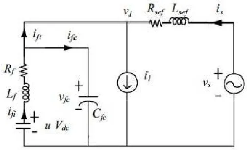
This section presents a generalized procedure to select external inductor for improvement in D-STATCOM voltage regulation capability while reducing the current rating of VSI. Fig. 4 shows single phase equivalent D-STATCOM circuit diagram in distribution system. With balanced voltages, source current will be
…... (6)
Where Rsef = Rs +Rext and Xsef = Xs +Xext are effective feeder resistance and reactance, respectively. Rext is equivalent series resistance (ESR) of external inductor, and will be small.
Ѳsef = ⁄ …... (7)
Z sef = + …... (8)
With and as effective impedance angle and effective feeder impedance, respectively, the imaginary component of Isis given as
= ( )…... (9)
With the addition of external impedance, the effective feeder impedance becomes predominantly inductive. Hence, Zsef≈Xsef. Therefore, approximated will be
ISSN (Print) : 2320 – 3765 ISSN (Online): 2278 – 8875
I
nternational
J
ournal of
A
dvanced
R
esearch in
E
lectrical,
E
lectronics and
I
nstrumentation
E
ngineering
(A High Impact Factor, Monthly, Peer Reviewed Journal)
Website: www.ijareeie.com
Vol. 7, Issue 5, May 2018
DSTATCOM Power rating (Svsi) is given as follows:
√2 ⁄
=√3) …... (11)
Where i is the rms phase current rating of the VSI and Vdc is the voltage maintained at the dc capacitors. The D-STATCOM aims to inject harmonic and reactive current component of load currents. Suppose Ilim is the maximum rms reactive and harmonic current rating of the load, then the value of Compensator current used for voltage regulation (same as ) is obtained by subtracting Ilim from and given as
follows:
Fig. 2.4 Single phase equivalent circuit of DSTATCOM topology with external inductor in distribution system. I = - = √2 / √3 …... (12)
Comparing (8) and (10) while using value of δ from (4), following expression is obtained:
=
+ ⁄3
( )
+
…... . (13)
The above expression is used to compute the value of external inductor. Design example of external inductor, used for this work, is given in next section.
2.4 FLEXIBLE CONTROL STRATEGY
ISSN (Print) : 2320 – 3765 ISSN (Online): 2278 – 8875
I
nternational
J
ournal of
A
dvanced
R
esearch in
E
lectrical,
E
lectronics and
I
nstrumentation
E
ngineering
(A High Impact Factor, Monthly, Peer Reviewed Journal)
Website: www.ijareeie.com
Vol. 7, Issue 5, May 2018
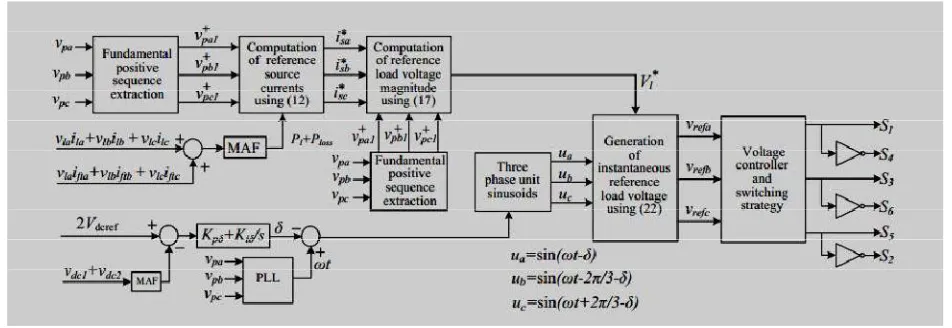
(PI) controller is used to control the load angle which helps in regulating the dc bus voltage at a reference value. Finally, three phase
reference load voltages are generated.
2.5. Derivation of Dynamic Reference Voltage Magnitude (Vl* )
In conventional VCM operation of DSTATCOM, the reference load voltage is maintained at a constant value of 1.0p.u. [10]–[12]. Source currents cannot be controlled in this reference generation scheme. Therefore, power factor will not be unity and source exchanges reactive power with the system even at nominal supply. To overcome this limitation, a flexible control strategy is developed to generate reference
2.6 SIMULATION PARAMETERS
System Quantities Values
Source voltage 240 V rms L-N (1.0 P.U), 50 hz Feeder Impedance
= 0.3Ω = 0.3 . = 3.185
External Impedance = 6.7 = 0.007Ω
Linear Load Zta= 30+j62.8 Ω , Ztb= 40+j78.5 Ω , Ztc= 50+j50.5 Ω
Non Linear Load Three Phase rectifier supplying R-L load of 50 Ω and 200 mH VSI parameter Vdc= 520v , Cdc = 2600 F, Lf= 5 mH, Cf= 20 F, = 30
Pi gain = 1.8
2.6.1)NORMAL OPERATION:-
It is defined as the condition when load voltage lies between 0.9 to 1.1 P.UIn this case, the proposed flexible control strategy controls load voltages such that the source currents are balanced sinusoidal and VSI does not exchange any reactive power with the source. Hence, the source supplies only fundamental positive sequence current component to support the average loads power and VSI losses.
=
∆
( + …... (14)
= ∫ ( + + ) …... (15)
= ∫ ( + + ) …... (16)
Instantaneous PCC voltage and reference source current in phase-a can be defined as Follows
+ − + =√2
ISSN (Print) : 2320 – 3765 ISSN (Online): 2278 – 8875
I
nternational
J
ournal of
A
dvanced
R
esearch in
E
lectrical,
E
lectronics and
I
nstrumentation
E
ngineering
(A High Impact Factor, Monthly, Peer Reviewed Journal)
Website: www.ijareeie.com
Vol. 7, Issue 5, May 2018
Fig.2.5 Block diagram of proposed flexible control strategy
+ − + =√2
…... (18)
Where V+pa1 and ϕ+pa1 are rms voltage and angle of fundamental positive sequence voltage in phase-a, respectively. = + - …... (19)
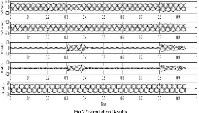
The parameters of DSTATCOM compensated distribution system are given in Table I. Usual scenario in distribution system having resistive feeder impedance are considered. PSCAD software is used to simulate the system. Firstly, theD-STATCOM is operated in conventional VCM, i.e.1) Without external inductor and 2) with a reference voltage of 1.0 P.U or 230 V rms. The steady state waveforms ofthree phase PCC voltages, load voltages, source currents, filter currents, and load currents are shown in Figs. 7(a)-(e), respectively. Here, the DSTATCOM has to compensate only for feeder drop. However, from the load voltage waveform shown in
ISSN (Print) : 2320 – 3765 ISSN (Online): 2278 – 8875
I
nternational
J
ournal of
A
dvanced
R
esearch in
E
lectrical,
E
lectronics and
I
nstrumentation
E
ngineering
(A High Impact Factor, Monthly, Peer Reviewed Journal)
Website: www.ijareeie.com
Vol. 7, Issue 5, May 2018
2.7 MATLAB DESIGN
fig.2.8 MATLAB simulation design
Fig 2.9 shows detail block design of MATLAB simulation This Design divided in to two section First section generates three phase reference load voltage and second section generate D.C bus reference voltage.math function, trigonometric function, Mean value function are used while design. Universal block implement a bridge of selected power electronic device.In the first section
, ,, ,are load voltage, load current and effective feeder load current.MUX block is used to generate three phase load
voltage and load current. Then product block multiply the load voltage and load current. Then SUM block add the output of MUX. After that MATH function block introduce ,The Math Function block performs numerous common mathematical functions.after that finally signal gives to PWM that is pulse with modulation block which generate three phase reference load voltage.
In the second section Vdc1 and Vdc2 are the source block, both voltage are add by the SUM block. Then the signal reaches to mean value function block this block compute the mean value of input signal over a running window of one cycle. After that signal goes to PLL block , it is a 3 phase lock loop system can be used to synchronies on a set of variable frequency. By using this MATLAB design simulation results can be validate.
ISSN (Print) : 2320 – 3765 ISSN (Online): 2278 – 8875
I
nternational
J
ournal of
A
dvanced
R
esearch in
E
lectrical,
E
lectronics and
I
nstrumentation
E
ngineering
(A High Impact Factor, Monthly, Peer Reviewed Journal)
Website: www.ijareeie.com
Vol. 7, Issue 5, May 2018
The filter and load currents are shown in Figs.2.9 (iv) and (v),respectively. These waveforms validate the performance of flexible control strategy as
1) source does not exchange reactive power from the system,
2) filter does not supply additional current and reduces system losses, and 3) UPF is maintained at the PCC.
These features are not available in conventional DSTATCOM operating in VCM. Approximate losses in the system are given as follows:
+ ( ) + ( )
= 3 )... (20)
In conventional scheme, the source always exchanges reactive power. Hence, will be non-zero. Also, this current is supplied by the filter i.e., If1 will be higher. However, in proposed scheme, it is seen that the source does not exchange reactive power in normal operation. Hence, = 0 and If1 is reduced. Hence, proposed scheme reduces losses in the system and utilizes smaller VSI ratings. Small power losses will be there due to the ESR of the external inductor. However, the losses in the ESR will be much smaller than that of reduction of power losses from the conventional D-STATCOM operation. Voltage sag is created by reducing the source voltage to 0.6 P.U. at t = 0.3 s for 4 cycles. Fig. 2.9 (vi) shows the PCC voltages. Control of reference load voltage based on the coordinated control offundamental load current, PCC voltage, and voltage across the external inductor allows D-STATCOM to set different constant reference voltage. The proposed scheme detects voltage sag and load voltage is changed to 0.9 P.U. The waveforms of load voltages are shown in Fig.2.9 (vii)..The source currents are increased during sag period as illustrated in Fig.2.9 (viii). Fig.2.9 (ix) Fig.2.9 (ix) shows the filter currents which increase during sag period to support the load voltage. The load currents waveforms presented in Fig.2.9 (x) is nearly constant during entire operation. With the results of Figs.2.9 (vi)-(x), it can be concluded that the proposed scheme makes load operation continuous. Algorithm detects swell and maintains load voltage at 1.1 P.U. The waveforms are shown in Fig. 2.9 (xii). The waveforms of the source, filter, and load currents are shown in Figs.2.9 (xiii)- (xv), respectively. The filter currents increase during well which increases the source currents as well. Load currents are nearly constant throughout the operation. Once sag is removed, it is detected by the algorithm and system is brought to the steady state conditions. It confirms effectiveness of the proposed scheme.
III. CONCLUSION
This paper has presented design, operation, and control of a D-STATCOM operating in voltage control mode (VCM). After detailed design procedure The DSTATCOM has improved voltage regulation capability with a reduced current rating VSI, reduced losses in the VSI and feeder. Simulation and experimental results validate the effectiveness of the proposed solution. The external inductor is a very simple and cheap solution for improving the voltage regulation. The future work includes operation of this fixed inductor as a controlled reactor so that its effect can be minimized by varying its inductance.
introduction of external inductor greatly improves the D-STATCOM voltage regulation capability. Additionally, due to increased effective feeder impedance the current requirement for sag mitigation also reduces. Moreover, if ESR of the external inductors included, then the equivalent feeder impedance angle changes slightly (i.e.from 83 degree to 80.45 degree), and has negligible effect on the expression obtained inas well as the voltage regulation capability of D-STATCOM.
REFERENCES [1] M. H. Bollen, Understanding power quality problems. vol. 3, IEEE press New York, 2000.
[2] S. Ostroznik, P. Bajec, and P. Zajec, “A study of a hybrid filter,” IEEE Trans. Ind. Electron., vol. 57, no. 3, pp. 935–942, Mar. 2010.
[3] C. Kumar and M. Mishra, “A voltage-controlled DSTATCOM for power quality improvement,” IEEE Trans. Power Del., vol. 29, no. 3, pp. 1499– 1507, June 2014.
ISSN (Print) : 2320 – 3765 ISSN (Online): 2278 – 8875
I
nternational
J
ournal of
A
dvanced
R
esearch in
E
lectrical,
E
lectronics and
I
nstrumentation
E
ngineering
(A High Impact Factor, Monthly, Peer Reviewed Journal)
Website: www.ijareeie.com
Vol. 7, Issue 5, May 2018
[5] T. Aziz, M. Hossain, T. Saha, and N. Mithulananthan, “VAR planning with tuning of STATCOM in a DG integrated industrial system,” IEEE Trans. Power Del., vol. 28, no. 2, pp. 875–885, Apr. 2013.
[6] S. Karanki, N. Geddada, Mahesh K. Mishra, and B. Kumar, “A DSTATCOM topology with reduced dc-link voltage rating for load compensation with nonstiff source,” IEEE Trans. Power Electron, vol. 27, no. 3, pp. 1201–1211, Mar. 2012.
[7] M. Aredes, J. Hafner, and K. Heumann, “Three-phase four-wire shunt active filter control strategies,” IEEE Trans. Power Electron., vol. 12, no. 2, pp. 311–318, Mar. 1997.
[8] B. Singh, K. Al-Haddad, and A. Chandra, “A new control approach to three-phase active filter for harmonics and reactive power compensation,” IEEE Trans. Powe Sys., vol. 13, no. 1, pp. 133–138, Feb 1998.
[9] S. Narula, B. Singh, and G. Bhuvaneswari, “Improved power-qualitybased welding power supply with overcurrent handling capability,” IEEE Trans. Power Electron., vol. 31, no. 4, pp. 2850–2859, April 2016.
[10] H. Fujita and H. Akagi, “Voltage-regulation performance of a shunt active filter intended for installation on a power distribution system,” IEEE Trans. Power Electron., vol. 22, no. 3, pp. 1046–1053, May 2007.
[11] R. Gupta, A. Ghosh, and A. Joshi, “Performance comparison of VSCbased shunt and series compensators used for load voltage control in distribution systems,” IEEE Trans. Power Del., vol. 26, no. 1, pp. 268– 278, Jan. 2011.