ISSN 2286-4822 www.euacademic.org
Impact Factor: 3.4546 (UIF) DRJI Value: 5.9 (B+)
Simulation of Internal Ballistics Solid Rocket Motor
MAGDI ABELRAZIG ELHAG MOHAMED
School of Mechanical Engineering Sudan University of Science & Technology, Khartoum, Sudan
MOHAMED ELTAYEB MANSOUR
Associate Professor, Aviation Department Karary University, Khartoum, Sudan
Abstract:
Determination of the grain geometry is one of the critical steps during the design of a solid propellant rocket motor. Because, performance prediction of the solid propellant rocket motor is achieved if burning surface area of the propellant grain is known as it recedes.
Solid Rocket Motors (SRM) were very expensive. In the design to develop the solid propellant rocket motors, the use of numerical tools able to simulate, predict and reconstruct the behavior of a given motor in all its operative conditions is particularly important in order to decrease all the planning and costs to avoid made destructive test for checking internal ballistic which is very expensive.
The main goal of this work is to study and simulate charged motor for long range rocket (122mm) motor internal ballistics (thrust & pressure), during the quasi steady state by means of a commercial numerical tool, ANSYS FLUENT.
The internal ballistics model constructed in this study is a 2-D axis symmetric model, based on several assumptions. Among them is the assumption that there is no contribution of the erosive burning and the dynamic burning in the burning rate model.
In this study some of the conventional two dimensional grain burn backs are analyzed and thrust - pressure time histories are predicted by making some graphs. These graphs are validated by comparing the ground static firing test data obtained by Ballistic Test Motor.
ANSYS FLUENT simulation can improved to use in investigating other solid rocket motors which used in missile or rockets motor or any other type of ammunitions which is too high cost to investigate with experimental ground firing test station.
Key words: Thrust, ANSYS FLUENT, Pressure, solid propellant, Internal Ballistic, Solid Rocket Motor.
1. INTRODUCTION
First part of the design process of the solid propellant rocket motor is the determination of the flight-mission requirements. After that, thrust-time curve is prepared according to requirements. At this point, internal ballistic calculations are performed to estimate chamber pressure of the rocket motor [1, 3, 4, 9].
Solid rockets motors (SRM) store propellants in solid form. It is the simplest of all rocket propulsion system designs .The fuel is typically powdered aluminum and the oxidizer is ammonium perchlorate. A synthetic rubber binder such as polybutadiene holds the fuel and oxidizer powders together. Though lower performing than liquid propellant rockets, the operational simplicity of a solid rocket motor often makes it the propulsion system of choice [2,4] .
A solid-propellant rocket motor consists of a casing, usually steel, filled with a solid propellant charge, called the grain, which contains all the chemical constituents (fuel plus oxidizer) for complete burning, the nozzle, internal insulation and the ignitor, as shown in Figure 1.1. The combustion chamber is where the burning of propellants takes place at high pressure. The chamber must be strong enough to contain the high pressure generated by, and the high temperature resulting from, the combustion process. Because of the high temperature and heat transfer, the chamber and nozzle are usually cooled. The chamber must also be of sufficient length to ensure complete combustion before the gases enter the nozzle. When ignited, the propellant compounds burn rapidly, expelling hot gases from a nozzle to produce thrust. The propellant burns from the center out toward the sides of the casing. The shape of the center channel determines the rate and pattern of the burn, thus providing a means to control thrust. Unlike liquid-propellant engines, solid-liquid-propellant motors can't be shut down. Once ignited, they burn until all the propellant is exhausted[10].
Figure 1: Solid Rocket Motor (SRM)
1.1 Thrust
opposite direction on that system. The force applied on a surface in a direction perpendicular or normal to the surface is called thrust. In math and physics, this is described by Isaac Newton's second and third laws. Thrust is used to describe how strongly an engine pushes [4].
Figure 2: Thrust variables & general thrust equation
The thrust F is the resultant of the forces due to the pressures exerted on the inner and outer walls by the combustion gases and the surrounding atmosphere, taking the boundary between the inner and outer surfaces as the cross section of the exit of the nozzle.
1.2 Thrust-Time-Curve
A thrust curve, sometimes known as a "performance curve" or "thrust profile" is a graph of the thrust of an engine or motor, (usually a rocket) with respect to time. Most motors do not produce linear thrust (thrust which increases at a constant rate with time). Instead, they produce a curve of some type, where thrust will slowly rise to a peak, and then fall, or "tail off". Rocket engines, particularly solid-fuel rocket motors, produce very consistent thrust curves, making this a useful metric for judging their performance [5].
1.3 Pressure.
Pressure is a force exerted by the substance per unit area on another substance. The pressure of a gas is the force that the gas exerts on the walls of its container. Pressure (symbol: p or P) is the force applied perpendicular to the surface of an object per unit area over which that force is distributed.
Pressure is defined to be the amount of force exerted per area[1,3,4]..
P=F/A (1)
1.4 Pressure-Time-Curve
Pressure time curve shows airway pressure, breath timing, the breath type delivered and patient versus machine triggering [2, 4, 5, 6, 7].
Figure 3: Pressure-Time Curve
1.5 Burning rate
changes under various conditions, is of fundamental importance in the successful design of a solid rocket motor.
Figure 4: Simplified model of propellant burning
Burning rate is the principal ballistic property of a solid propellant, necessary for motor design and also used for control of propellant quality in production. The burning rate varies with pressure, and the rate-pressure relationship is most commonly determined by testing either strands or small motors at several different relatively constant pressures. [1, 4, 6, 11].
1.6 Vielle’s - de Saint Robert's law:
For SRM ignition transient modeling, in order to avoid the complications of the direct solution of the combustion wave, it is common practice to use simple empirical relations for the burning rate evaluation, for example, the largely and successfully used expression of Vielle’s-de Saint Robert's law [2,8].
(2)
1.7 Tail off
becomes smaller and smaller, a rapid decrease of the chamber pressure occurs, and combustion actuations and sliver generation can also occur.
This operative phase is, therefore, characterized by unsteady events, related to the chamber pressure decrease in time, mixing of gases coming from the residual grain propellant combustion and case thermal protections ablations. Thus, they need to be described correctly by an accurate burning surface evolution evaluation [8].
2. Model description:
The Solid Rocket Motor of 122mm rocket consists of motor case (122mm diameter, total length 1945±1mm, with nozzle 2228mm), nozzle (divergent convergent), propellant grain, internal insulation and the igniter; figure (1-6).
Figure 5: Simplified model of (SRM)
The SRM of 122mm motor was studied. It has a relatively simple conical shape of the grain propellant and a simple cylindrical case. The propellant used in SRM of 122mm its composition and characteristics are reported in the tables below. It has a burning rate with parameter a= 10 at temperature 20oC, a burning rate exponent of APN De Vieille Saint Robert of n = 0.3 and a density of about 1.76 Kg/m3.
function of ensuring that the heat does not penetrate far below the surface of the grain, which could cause detonation. The opacifier also prevents sub-surface overheating and localized premature ignition in the grains where imperfections absorbing the thermal radiation are present.
Table 1: Formulation sheet
Table 2: Mechanical properties
3- Simulation of the model.
3.1-ANSYS FLUENT Model preprocessing for 122 mm (SRM) steps:
Figure 5: Mesh Distribution
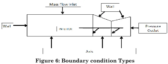
2- Specify Boundary Types in GAMBIT as in figure (6).
Figure 6: Boundary condition Types
3-To calculate burning rate of the grain which is had star shape at front and cylindrical bore shape we build program using C++ language and used User Define Function (UDF).
4-We choose Models.
3.2- Post processing (simulation result).
There are several quasi-steady formulations to predict the burning rate of an energetic solid material. One of them is the APN model, which is an empirical model suitable for composite propellants in the absence of a more suitable fundamental combustion model. The APN model approximates the burning rate as solely dependent on the mean local pressure using the Vielle's or Saint Robert's law:
temperature coefficient, and is the burning rate exponent, or the combustion index, and it is independent of the initial grain temperature and describes the influence of chamber pressure on the burning rate.
T T n
n
P
e
a
aP
r
0
0
(3) Propellant burning rate
Chamber pressure (MPa) Propellant temperature T (℃)
Referenced temperature T0 =20℃ Pressure exponent n =0.3
Burning rate coefficient a (cm/ ((MPa) n·S)) T0=20℃,
MPa
s
cm
a
0
1
.
001
/
n
0.00241/℃3.2.1-Simulation under 20 ℃:
Propellant burning rate n T T n
P
e
a
aP
r
0
0
n=0.3 a = 10 T= 20℃
Figure 7: Thrust – Time curve (20℃)
Contours of custom field functions
Figure 9: Pressure – Time curve (20℃)
Figure 9: Contours of static pressure (20℃)
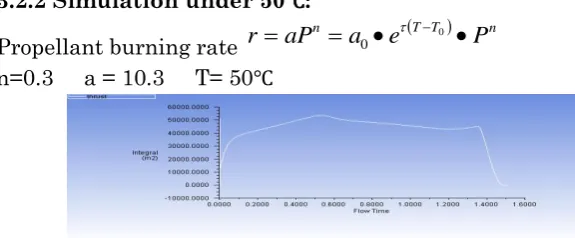
3.2.2 Simulation under 50℃:
Propellant burning rate
r
aP
n
a
0
e
TT0
P
n
n=0.3 a = 10.3 T= 50℃
Figure 10: Thrust – Time curve (50℃)
Contours of custom field functions
Figure 12: Pressure – Time curve (50℃)
Figure 13: Contours of static pressure (50℃)
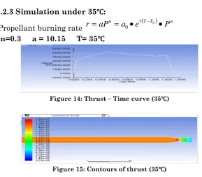
3.2.3 Simulation under 35℃:
Propellant burning rate
r
aP
n
a
0
e
TT0
P
n
n=0.3 a = 10.15 T= 35℃
Figure 14: Thrust – Time curve (35℃)
Figure 16: Pressure – Time curve (35℃)
Figure 17: Contours of static pressure (35℃)
Figure 18: comparison of thrust at different temperature
Figure 19: comparison of pressure at different temperature
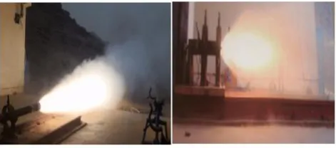
4. Experimental Work Setting.
4.1Experimental test (Ground static test station).
put the pressure sensor at the front side inside the motor case where we put thrust sensor at the front side in front of the motor near to the metal which suspending to the concrete wall. As shown in figure 17.
The ground static test station is consisting of:- a. Thrust sensors its maximum rang (0~50) KN. b. Pressure sensors it’s maximum range (0~20)MPa. c. Control room.
d. Data acquisition unit for analysis of data. e. Temperature gauge.
Implement firing static test (experimental test) for the new models (in different temperatures).
Figure 20: Ground static Test Setting(SRM on the static test stand)
4.2 Experimental test results and discussion
4.2.2 Thrust results:
Figure 22: Thrust at 50℃
Figure 23: Thrust at 35℃
Figure 25: Comparison thrust at different temperatures (20,35,50) ℃
4.2.3 Pressure result
Figure 26: Comparison pressure at different temperatures (20,35,50) ℃
5. RESULT & DISCUSSION
From table 3:
1-We can see that the temperature had reverse proportion with the thrust burning time and also with pressure burning time at simulation and experimental test.
2-The Burning rate coefficient had reverse proportion with the thrust burning time and also with pressure burning time at simulation and experimental test.
3-The deviation of thrust time and pressure time between simulation and experimental is acceptable.
Table 4: Tail off stage results from thrust and pressure time curve at different temperature.
From table 4:
1-We can see that the temperature and burning rate coefficient had reverse proportion with the thrust curve and also with pressure curve at simulation and experimental test.
CONCLUSION
In this work we used 2D ANSYS FLUENT simulation to simulate the internal ballistic for 122mm (SRM).
The results about the internal ballistic (SRM) (thrust & pressure) between simulation and experimental show good results and was much closed, so we can use ANSYS FLUENT to simulate other different parameters.
Analytical method and Software simulation can integrate to design (SRM) and solve many kinds of problem because it’s very economic and safe and faster than experimental tests.
The use of CFD allowed resolution of a much greater level of detail than could have been determined with the experimental results alone. A thorough understanding of the experimental setup and its limitations were acquired which will help in future test design and analysis.’ CFD tools and techniques developed during this effort can aid in prediction of hot gas behavior in narrow solid rocket motor joints.
The benefit of the simulation will be plan to get the performance of motor and to compare the results with testing data and to validate the design data with the testing data , and the results will be an important for technical decision for establishing production lines.
Acknowledgments
REFERENCES
[1] Cengizhan YILDIRIM, and M. Halûk AKSEL1, “NUMERICAL SIMULATION OF THE GRAIN BURNBACKIN SOLID PROPELLANT ROCKET MOTOR”, American Institute of Aeronautics and Astronautics. July 2005,Tucson, Arizona. [2]Marius Ionuţ MĂRMUREANU “SOLID ROCKET MOTOR INTERNAL BALLISTICS SIMULATION USING DIFFERENT BURNING RATE MODELS”, U.P.B. Sci. Bull., Series D, Vol. 76, Iss. 4, 2014.
[3]“Design Methods in Solid Rocket Motor”, AGARD-LS-150, 1988.
[4]Michael A. Willcox, M. Quinn Brewster, K. C. Tang,‡ D. Scott Stewart,§ and Igor Kuznetsov “Solid Rocket Motor Internal Ballistics Simulation Using Three-Dimensional Grain Burnback”, JOURNAL OF PROPULSION AND POWER ,Vol. 23, No. 3, May–June 2007.
[5]David R. Greatrix“Parametric Evaluation of Solid Rocket Motor Internal Ballistics”, American Institute of Aeronautics and Astronautics.July 2010, Nashville, TN.
[6] Michael A. Willcox, M. Quinn Brewster, K. C. Tang, D. Scott Stewart, and Igor Kuznetsov“Solid Rocket Motor Internal Ballistics Simulation Using Three-Dimensional Grain Burnback ”, JOURNAL OF PROPULSION AND POWER .Vol. 23, No. 3, May–June 2007
[7] F. M. Najjar, J. Ferry, B. Wasistho, and S. Balachandar, “Full-Physics Large-Scale Multiphase
Large Eddy Simulations of Flow inside Solid Rocket Motors ”, American Institute of Aeronautics and Astronautics.July 7–10, 2002/Indianapolis.
[9] B. Wasistho and R. D. Moser, “Simulation Strategy of Turbulent Internal Flow in Solid Rocket Motor”, JOURNAL OF PROPULSION AND POWER,Vol. 21, No. 2, March–April 2005. [10] Jinwei Fan,Futao Tan , “Analysis of Major Defects and Nondestructive Testing Methods for Solid Rocket Motor”, Applied Mechanics and Materials Vols. 365-366 (2013) pp 618-622, © (2013) Trans Tech Publications, Switzerland
doi:10.4028/www.scientific.net/AMM.365-366.618