Electronic Thesis and Dissertation Repository
11-16-2015 12:00 AM
Development of an in-vitro passive and active motion Simulator
Development of an in-vitro passive and active motion Simulator
for the investigation of wrist function and Kinematics
for the investigation of wrist function and Kinematics
Duncan J. Iglesias
The University of Western Ontario
Supervisor
Dr. James Johnson
The University of Western Ontario
Graduate Program in Biomedical Engineering
A thesis submitted in partial fulfillment of the requirements for the degree in Master of Engineering Science
© Duncan J. Iglesias 2015
Follow this and additional works at: https://ir.lib.uwo.ca/etd
Part of the Biomechanical Engineering Commons, and the Biomedical Engineering and Bioengineering Commons
Recommended Citation Recommended Citation
Iglesias, Duncan J., "Development of an in-vitro passive and active motion Simulator for the investigation of wrist function and Kinematics" (2015). Electronic Thesis and Dissertation Repository. 3443.
https://ir.lib.uwo.ca/etd/3443
This Dissertation/Thesis is brought to you for free and open access by Scholarship@Western. It has been accepted for inclusion in Electronic Thesis and Dissertation Repository by an authorized administrator of
by
Duncan Iglesias
Graduate Program in Biomedical Engineering
A thesis submitted in partial fulfillment
of the requirements for the degree of
Masters of Engineering Science
The School of Graduate and Postdoctoral Studies
The University of Western Ontario
London, Ontario, Canada
This thesis outlines the design and development of an active motion simulator for the
investi-gation of wrist kinematics in multiple gravity loaded positions. Using optical trackers on the
third metacarpal, radius, and ulna, the position of the wrist was monitored in real time without
introducing material incompatibilities as present for electromagnetic tracking systems.
Per-formance of the system was performed using a series of five cadaver upper limbs that
com-pared the ability to produce repeatable trials using unrestrained active motion techniques over
passive manipulation methods. Comparisons to achieve static positions as well as motion trials
in flexion-extension and radial-ulnar deviation planes proved the superior performance of
com-puter controlled motion over that of passive manipulation. Investigation into the application of
tendon portioning to modelin-vivoconditions more accurately suggest that they may improve
overall quality of motion.
Keywords: Active Motion Simulator, Wrist Kinematics, Reparative Surgery Assessment, Muscle Portioning, Gravitational Effects
Chapter 1: Introduction
Duncan Iglesias - sole author
Chapter 2: Design & Development
Duncan Iglesias - developed platform & control system, study design, data collection, statistical analysis, wrote manuscript
Josh Giles - technical assistance
Jason Lockhart - apparatus design, data collection
James Johnson - study design, reviewed manuscript
Graham King - study design, specimen preparation, reviewed manuscript
Chapter 3: Gravitational Effects
Duncan Iglesias - developed controller, study design, data collection, statistical analysis, wrote manuscript
Jason Lockhart - apparatus design, data collection
James Johnson - study design, reviewed manuscript
Graham King - study design, specimen preparation, reviewed manuscript
Chapter 4: Tendon Portioning
Duncan Iglesias - developed controller, study design, data collection, statistical analysis, wrote manuscript
Jason Lockhart - data collection
James Johnson - study design, reviewed manuscript
Graham King - study design, specimen preparation, reviewed manuscript
Chapter 5: Discussion & Conclusions
Duncan Iglesias - sole author
I would like to start by thanking my supervisors, Dr. J. Johnson & Dr. G. King, for the
incredible opportunity to work at the Hand & Upper Limb Centre (HULC) and to be part of
the first class research that is coming out of this lab. Thank you for your unwaivering support
throughout the entire process, the freedom to explore my own avenues, and the confidence you
put in right from the very start. The skills I have gained during my time as a masters student are
by far the most valuable to date. Dr. King, thank you for all the early mornings you donated to
help with specimen preparation on testing days. It was a pleasure being able to work so closely
with such a skilled surgeon and experience the ease of which you operate.
To Mark, without you I never would have pursued my masters at Western University in
Biomed-ical Engineering. The connection you made between Dr. Johnson and myself was truly life
changing; I can not imagine where I would have been right now if you had not suggested that
I take over for you at the HULC. It was only fitting that I adopted your wrist simulator project,
the ’Masaumulator’, and carried on with the research that you, Dr. Bradon, and Dr. Masao
were so involved with. Best of luck to you in your hybrid career of engineering and
physio-therapy.
To my sister and her ever growing family on the farm, you acted as my private rehab allowing
me to escape away to hang by the pool and play with cows when overwhelmed with school.
Russel and Oliver are two beautiful little boys and I am excited for the third one coming this
December! Stefan is pretty cool too. Thank you to my parents for your food and beverage
donations over the past two years, it kept me going when the only thing left in my cupboards
were red solo cups.
Jason Lockhart, thank you for all your hard work this past summer. Many of the images
and data in this thesis I can thank you for. You put many long hours into organizing data and
creating bone models not to mention the passive guide rail and automated LED array that you
prototyped from scratch for me. Josh Giles, you set me up from the start and showed me the
ropes with the fundamentals of motor communication with the SmartMotors and were always
ff
that were ultimately incorporated into my thesis.
Thank you to all the students and researchers from ’the Tank’ who were always willing to
donate their time to help me during back to back 21-hour test days and then still have the
en-ergy to play a round of tennis during lunch at Doidge Park. I may be a fun guy, but you are all
way ’funner’. I will be sure to return the favour the best I can.
Matt Stokes, you constantly motivated me to work harder than ever before and approach
tech-nical challenges in manors outside the norm. Many countless hours were spent at ’Tech House’
mulling ideas over on the wall of white boards or solving our most recent thesis stumpers
be-tween Halo sessions. I have truly valued our friendship over these past two years, and I wish
you the best of luck with your career down in California, I will be sure to keep tabs.
Finally, to Emilie Brent for being such an understanding girlfriend and having unlimited
pa-tience for when I went missing for days on end during periods of intense deadlines, overloaded
testing schedules, conferences, and those random side projects that stole my attention more
than I had originally anticipated. You were always right there when I reemerged and were
ready to listen to whatever rant or idea that was currently occupying my mind, and no matter
how technical or in depth I got you always showed the utmost interest in what I had to say.
You are my psychiatrist, my partner in crime, and my best friend. I truly cherish what we have
together.
Abstract ii
Co-Authorship Statement iii
Acknowledgments iv
List of Figures xii
List of Tables xv
1 Introduction 1
1.1 Anatomy of the Wrist & Hand . . . 2
1.1.1 Osteology . . . 2
1.1.1.1 Radius . . . 2
1.1.1.2 Ulna . . . 4
1.1.1.3 Carpal Bones . . . 6
1.1.1.4 Metacarpals . . . 6
1.1.1.5 Phalanges . . . 7
1.1.2 Ligaments . . . 8
1.1.2.1 Radiocarpal Ligaments . . . 8
1.1.2.2 Ulnocarpal Ligaments . . . 8
1.1.2.3 Distal Radioulnar Ligaments . . . 9
1.1.2.4 Intercarpal Ligaments . . . 9
1.1.2.5 Carpometacarpal Ligaments . . . 9
1.1.3 Joint Capsules . . . 11
1.1.3.1 Distal Radioulnar Joint (DRUJ) . . . 11
1.1.3.2 Radiocarpal Joint . . . 11
1.1.3.3 Intercarpal Joint . . . 11
1.1.3.4 Carpometacarpal Joint . . . 12
1.1.4 Myology . . . 13
1.1.4.1 Volar Compartment . . . 15
1.1.4.2 Dorsal Compartment . . . 15
1.1.4.3 Forearm Rotators . . . 16
1.2 Wrist Kinematics & Biomechanics . . . 17
1.2.1 Range of Motion . . . 17
1.2.1.1 Flexion-Extension Motion . . . 17
1.2.2 Joint Geometry . . . 19
1.2.3 Antagonistic Muscle Pairs . . . 20
1.2.4 Cross Sectional Area . . . 21
1.2.5 Moment Arms . . . 21
1.2.6 Kinematic Chains . . . 21
1.3 Euler Angles . . . 22
1.4 Coordinate Transformations . . . 24
1.4.1 Transformation Matrix . . . 24
1.4.2 Transformation Chain . . . 25
1.5 Body Segment Coordinate Systems . . . 26
1.6 Methods of Tracking . . . 32
1.6.1 Goniometer . . . 32
1.6.2 Inertial Measurement Units . . . 33
1.6.3 Image Based Tracking . . . 34
1.6.4 Electromagnetic Tracking Systems . . . 36
1.6.5 Optical Tracking Systems . . . 37
1.7 Clinical Complications . . . 39
1.7.1 Traumatic Injuries . . . 39
1.7.2 Degenerative Disease . . . 40
1.7.3 Bracing Methods . . . 40
1.8 Biomechanical Testing & Simulation of Motion Pathways . . . 41
1.8.1 In-SilicoSimulations . . . 42
1.8.2 In-VitroSimulators . . . 43
1.8.2.1 Passive Motion Simulators . . . 43
1.8.2.2 Active Motion Simulators . . . 45
1.9 Thesis Rationale . . . 48
1.10 Objectives & Hypotheses . . . 49
1.11 Thesis Overview . . . 50
Chapter One References . . . 50
2 Design, Development, & Validation 56 2.1 Introduction . . . 57
2.2 Methods . . . 59
2.2.1 Simulator Development . . . 59
2.2.1.1 Platform Design . . . 59
2.2.1.2 Motor Manifold . . . 60
2.2.1.3 Force Transducers . . . 60
2.2.1.4 Cable Guide Rail . . . 62
2.2.1.5 Humeral Clamp . . . 63
2.2.1.6 Ulnar Support Tower . . . 64
2.2.1.7 Passive Guide Rail . . . 65
2.2.2 Control Algorithm Development . . . 66
2.2.2.1 Force Controller Development . . . 66
2.2.3.2 Static Position Trials . . . 70
2.2.3.3 Center of Rotation Algorithm . . . 71
2.2.4 Outcome Variables & Statistical Analysis . . . 71
2.3 Results . . . 72
2.3.1 Repeatability of Motion Profiles . . . 72
2.3.1.1 FEM Motion Trials . . . 73
2.3.1.2 RUD Motion Trials . . . 74
2.3.1.3 Static Trials . . . 75
2.3.2 Center of Rotation Repeatability . . . 76
2.3.3 Repeatability of Tendon Forces . . . 77
2.3.3.1 Static Trials . . . 77
2.3.3.2 Motion Trials . . . 78
2.4 Discussion . . . 81
2.5 Conclusions . . . 84
Chapter Two References . . . 84
3 Gravitational Effects on Kinematics 87 3.1 Introduction . . . 88
3.2 Methods . . . 90
3.2.1 Specimen Preparation . . . 90
3.2.2 Data Collection . . . 90
3.2.3 Outcome Variables & Statistical Analysis . . . 91
3.3 Results . . . 92
3.3.1 Repeatability of Motion Profiles . . . 92
3.3.1.1 In-Plane Motions . . . 93
3.3.1.2 Out-of-Plane Motions . . . 96
3.3.2 Center of Rotation Repeatability . . . 99
3.3.3 Repeatability of Tendon Forces . . . 99
3.3.3.1 Static Trials . . . 100
3.3.3.2 Motion Trials . . . 101
3.4 Discussion . . . 103
3.5 Conclusions . . . 106
Chapter Three References . . . 106
4 Muscle Portioning 109 4.1 Introduction . . . 110
4.2 Methods . . . 112
4.3 Results . . . 114
4.3.1 Repeatability of Motion Trials . . . 114
4.3.1.1 In-Plane Motion Profiles . . . 114
4.3.1.2 Non-Planar Deviations . . . 117
4.3.2 Repeatability of Tendon Forces . . . 118
4.4.2 Effects of Portioning on Magnitude of Forces . . . 120
4.4.3 Developing Tendon Portioning Ratios . . . 120
4.5 Conclusions . . . 121
Chapter Four References . . . 122
5 Discussion & Conclusion 124 5.1 Summary . . . 125
5.2 Strengths & Limitations . . . 127
5.3 Current & Future Directions . . . 128
Chapter Five References . . . 128
A Establishing Bone Coordinate Systems 131 A.1 Local Reference Frame: Ulna . . . 132
A.2 Local Reference Frame: Radius . . . 133
A.3 Local Reference Frame: Metacarpal . . . 134
A.4 Applying Local Transforms . . . 135
B Force Transducer Calibration 136 B.1 Validation of a Load Cell . . . 136
B.2 Force Transducer Calibration . . . 137
C Simulator Mechanical Drawings 138 D Open Source Code & License Agreement 154 D.1 BSD License . . . 155
D.2 3D Circle Fitting MATLAB Algorithm . . . 156
D.3 3D Sphere Fitting MATLAB Algorithm . . . 159
E The Effects of Tissue Degradation on System Performance: An 18 Hour Test 161
F Bone Tracker Design 162
G Curriculum Vitae 164
1.1 Radius . . . 3
1.2 Ulna . . . 5
1.3 Carpal Bones & Metacarpals . . . 7
1.4 Ligaments of the Wrist and Hand . . . 10
1.5 Joints of the Wrist . . . 12
1.6 Muscles of the Wrist . . . 14
1.7 Range of Wrist Motion: Flexion-Extension . . . 17
1.8 Range of Wrist Motion: Radial-Ulnar Deviation . . . 18
1.9 Range of Wrist Motion: Pronation-Supination . . . 18
1.10 Antagonistic Muscle Pairs . . . 20
1.11 Euler Rotations of a Coordinate System . . . 22
1.12 Radial Coordinate System (ISB) . . . 29
1.13 Ulnar Coordinate System (ISB) . . . 30
1.14 Metacarpal Coordinate System (ISB) . . . 31
1.15 Goniometer . . . 32
1.16 Inertial Measuring Unit . . . 33
1.17 Image Based Tracking: Human Model . . . 34
1.18 Image Based Tracking: Model Matching . . . 35
1.19 Electromagnetic Tracking System . . . 36
1.20 Optical Tracking . . . 37
1.21 Open Reduction & Internal Fixation: Colles Fracture . . . 39
1.22 Full Wrist Arthroplasty . . . 40
1.23 Stewart Platform . . . 43
1.24 Pneumatic Array . . . 44
1.25 Dunning’s Active Simulator . . . 46
1.26 Werner’s Active Simulator . . . 47
2.1 Simulator Platform . . . 59
2.2 Motor Manifold & Transducer Placement . . . 61
2.3 Cable Guide Blocks . . . 62
2.4 Humeral Clamp . . . 63
2.5 Ulna Support Tower . . . 64
2.6 Passive Guide Rail . . . 65
2.7 Force-Motor Position PID Controller . . . 67
2.8 Position-Force PID Controller . . . 68
2.9 Krackow Suture Technique . . . 69
2.12 Repeatability of Motion: FEM Trials . . . 73
2.13 Repeatability of Motion: RUD Trials . . . 74
2.14 Repeatability of Position: Static Trials . . . 75
2.15 FEM Tendon Forces . . . 79
2.16 RUD Tendon Forces . . . 80
3.1 Center of Mass Shift in Neutral Gravity Loaded Position . . . 89
3.2 Repeatability of Motion Trials . . . 92
3.3 Repeatability of Motion Profiles: FEM Plane . . . 94
3.4 Repeatability of Motion Profiles: RUD Plane . . . 95
3.5 Repeatability of Motion Profiles: Non-Planar FEM . . . 97
3.6 Repeatability of Motion Profiles: Non-Planar RUD . . . 98
4.1 Repeatability of Motion Profiles: In-Plane Extension . . . 115
4.2 Repeatability of Motion Profiles: In-Plane Flexion . . . 116
4.3 Equal Loading vs. PCSA Portioning: Non-Planar Profile . . . 117
4.4 Equal Loading vs. PCSA Portioning: Forces . . . 118
A.1 ISB Coordinate System: Ulna . . . 132
A.2 ISB Coordinate System: Radius . . . 133
A.3 ISB Coordinate System: Metacarpal . . . 134
B.1 Load Cell Calibration . . . 136
F.1 Optical Tracker Mounts . . . 163
1.1 Types of Joints . . . 19
2.1 Center of Rotation of Motion Trials . . . 76
2.2 Static Forces . . . 77
2.3 Average Peak Active Tendon Forces . . . 78
3.1 Center of Rotation of Motion Trials . . . 99
3.2 Static Forces . . . 100
3.3 Average Peak Active Tendon Forces . . . 102
3.4 Neutral Static Position . . . 105
4.1 Portioning of Wrist Muscles . . . 113
Introduction
OVERVIEW:This chapter begins with a review of the basic anatomy and
biome-chanics of the wrist and forearm then continues with an overview of common joint
simulation methods and a comparative discussion of active and passive in-vitro
joint manipulation techniques. Previously implemented in-vitro simulators have
successfully reproduced motion using cadaveric specimens but their platforms lack
versatility for a range of kinematic investigations that stem from material
incom-patibilities, spatial tracking methods, and control limitations. This chapter
con-cludes with a discussion of the rationale for developing an active wrist and
fore-arm motion simulator that permits studies to be performed with the fore-arm in multiple
orientations.
1.1
Anatomy of the Wrist & Hand
An understanding of the anatomy of the wrist is crucial when studying wrist joint motion. The
following section will discuss the three main tissue structures of the wrist; osteology (bony
structure), ligaments, and myology (musculature).
1.1.1
Osteology
The wrist is comprised of 27 bones that articulate with the distal forearm to provide the rigid
structure necessary for everyday tasks [1]. Bones have two layers of tissues, a dense outer layer
known as cortical bone and a porous core known as cancellous bone [2], and are categorized
as long bones or irregular bones of which only long and short bones reside in the hand and
wrist. Long bones have three recognizable regions including both the proximal and distal ends
(epiphysis) that articulate with adjacent bones, and a shaft (diaphysis) [3]. Short bones are
equally wide as they are long to form a cube like structure for providing support and stability
with little relative movement [4].
1.1.1.1 Radius
The radius is the shorter of the two parallel long bones (Figure 1.1) that make up the forearm
and is located on the lateral side of the ulna when positioned in the anatomic position [5]. The
proximal end of the radius is cylindrical forming the radial head with a concave surface that
articulates with the capitellum of the distal humerus allowing for axial rotation of the forearm.
The radius narrows distally to form the radial neck that gives way to the shaft of the bone. A
rough projection on the medial, anterior surface of the proximal radius, known as the radial
tuberosity, is the insertion for the biceps brachii tendon responsible for supination [1]. The
shaft bows laterally along the length presenting three surfaces; dorsal border, volar border,
and medial border. The distal radius has of two articulating surfaces; the ulnar notch on the
medial side that interfaces with the ulna, and a smooth concave groove on the distal surface to
articulate with the lunate and scaphoid of the carpus. A conical projection on the lateral side
Figure 1.1: The radius is lateral bone of the forearm adjacent to the ulna. A: Proximal Radial
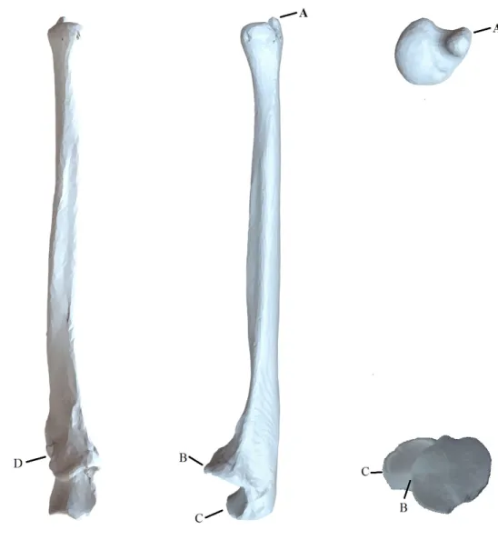
1.1.1.2 Ulna
The ulna is the longer of the two parallel long bones (Figure 1.2) that make up the forearm
and is located medial to the radius when in the neutral anatomical position [1]. Similar to the
radius the ulna has three segments; the proximal end, the shaft and the distal end. A major
difference from the radius is that the ulna converges to a smaller head distally while the radius
diverges to a larger metaphysis. The proximal end forms a cup-like projection that articulates
with the trochlea of the distal humerus consists of three parts: the olecranon process, semilunar
notch, and coronoid process. The olecranon process is the most proximal edge of the
projec-tion with an anteroinferior concave surface forming the upper porprojec-tion of the semilunar notch.
The coronoid process is the distal portion of the semilunar notch with a smooth anterosuperior
surface to close the cup-like structure of the semilunar notch. The semilunar notch is the
con-cave curvature residing between these projections creating a hinge joint structure to articulate
with the trochlea of the humerus. A concave groove on the lateral side of the proximal
extrem-ity, known as the radial notch, articulates with the radial head to allow rotation about the ulna
during supination and pronation. The distal end of the ulna contains two distinct eminences; a
round articulating surface on the lateral side to articulate with the distal radius, and the ulnar
Figure 1.2: The ulna is the medial bone of the forearm. A: Ulnar Styloid Process, B: Coronoid
1.1.1.3 Carpal Bones
There are eight short bones arranged into two rows of four that make up the carpal bones of the
hand (ossa carpi). The proximal row from the lateral side moving medially is composed of the
scaphoid, lunate, triquetrum, and pisiform while the distal row naming in the same direction
is composed of the trapezium, trapezoid, capitate, and hamate. For the purpose of this thesis
only three carpal bones will be discussed in detail: the scaphoid, the lunate, and the capitate
(Figure 1.3). The cube-like structure of the carpal bones present six surfaces on each bone of
which the volar and dorsal surfaces are intended for the attachment of ligaments and tendons
while the remaining four surfaces articulate with the surrounding bones.
The scaphoid is the largest and most lateral carpal bone in the proximal row with five
artic-ulations; the distal radius, trapezium, trapezoid, capitate, and lunate. The proximal surface is
convex in shape to articulate with the concave groove on the distal radius. The lunate has a deep
crescent-like form and has four articulations: scaphoid, hamate, triquetrum, and distal radius.
The proximal surface of the lunate is convex to articulate with the concave distal radius while
the distal surface is concave to articulate with the capitate. These two bones are the primary
means of axial load transfer from the forearm to the hand as they bridge the distal radius to the
remaining carpal bones [6]. The capitate is the largest of the carpal bones and moves in concert
with the third metacarpal during flexion-extension.
1.1.1.4 Metacarpals
The metacarpals are five long bones (Figure 1.3) that provide the structure of the palm of
the hand [6]. The naming convention starts medially moving laterally assigning the thumb as
the first metacarpal and the small finger as the fifth metacarpal. The proximal metacarpal is
concave and articulates with the respective carpal bone(s) in the distal row of the wrist. The
distal metacarpals are convex and articulate with the proximal phalanges. The shaft of each
metacarpal has three surfaces; medial, lateral, and dorsal. The medial and lateral surfaces
are concave while the dorsal surfaces are relatively flat allowing for insertion of the extensor
Figure 1.3: The five metacarpal bones of the hand (left) with their relative position to the distal
row of carpals; (proximal row) scaphoid, lunate, triquetrum, pisiform and (distal row) trapezium,
trapezoid, capitate, hamate [7]
1.1.1.5 Phalanges
The phalanges are the remaining 14 bones that make up the digits. Each digit contains three
phalanges named after their respective position; proximal, middle, and distal with an exception
to the thumb which only contains a proximal and distal phalanx [6]. These structures are not
involved with the motions of the wrist, rather they allow for the insertion of tendons from the
1.1.2
Ligaments
Ligaments are fibrous connective tissues composed of collagenous fibers that act to bind bones
together across an articulation to provide joint stability [8]. The ligaments in the hand and wrist
are categorized into intrinsic and extrinsic groups on both the volar and dorsal sides as seen in
(Figure 1.4). Intrinsic ligaments originate and insert on adjacent carpal bones to provide a rigid
framework for the wrist. Extrinsic ligaments bridge the carpal bones with either multiple carpal
bones, the proximal metacarpals, or the distal radius and ulna. Ligaments are conventionally
named with the bone of origin as the prefix and end with the bone of insertion. They are
also placed into broader categories that describe a group of ligaments such as: radiocarpal,
ulnocarpal, distal radioulnar, intercarpal,andcarpometacarpalligaments.
1.1.2.1 Radiocarpal Ligaments
There are four extrinsic radiocarpal ligaments on the palmar surface of the wrist that originate
from the distal lateral surface of the radial styloid and span medially into the adjacent carpals:
radioscaphocapitate, long radiolunate, short radiolunate, and radioscapholunate [9]. These
ligaments bridge the radius to the adjacent carpal bones to provide stability to the wrist
dur-ing extension. On the dorsal surface of the wrist there is only theradiocarpal ligament that
originates from the medial dorsal surface of the radial tubercle and inserts into the proximal
tubercles of the lunate and triquetrum to provide lateral support to the wrist during flexion [8].
1.1.2.2 Ulnocarpal Ligaments
The ulnocarpal ligaments are extrinsic and only present on the volar side of the wrist. The
ulnolunate ligament originates from the base the ulnar styloid process and inserts into the
proximal lunate. The ulnocapitateligament originates from the fovea of the ulnar head and
inserts into the proximal capitate. These ligaments provide medial support to the wrist during
1.1.2.3 Distal Radioulnar Ligaments
The distal radioulnar ligaments are responsible for maintaining the congruity between the ulnar
head and the ulnar notch of the radius, the distal radioulnar joint (DRUJ), during pronation and
supination [10]. Thedistal palmer radioulnar ligament originates from the anterior surface of
the ulnar notch on the radius and inserts on the anterior head of the ulnar head. Thedistal dorsal
radioulnar ligament originates from the posterior surface of the ulnar notch on the radius and
inserts into the posterior surface of the ulnar head.
1.1.2.4 Intercarpal Ligaments
The intercarpal ligaments are intrinsic to the wrist that maintain congruity between and
pro-vide rigid attachments that only allow slight movements between adjacent carpals. The
liga-ments are named with respect to the affected carpals and labeled as follows: scaphotrapezial,
scaphotrapezoidal, scapholunate, scaphocapitate, triquetrocapitate, lunotriquetral,
trapezio-trapezoid, capitotrapezio-trapezoid, capitohamate,andtriquetrohamate.
1.1.2.5 Carpometacarpal Ligaments
The carpometacarpal ligaments are responsible for attaching the proximal metacarpal to the
distal row of carpal bones on both the volar and dorsal side of the hand to maintain the stability
Figure 1.4: Ligaments of the right wrist and hand for the dorsal [top] and volar [bottom] views
1.1.3
Joint Capsules
The wrist is composed of an array of synovial joints and are classified into thedistal radioulnar
joint (DRUJ),radiocarpal joint, intercarpal joint, and thecarpometacarpal joints of which
only the first three will be discussed. Articular cartilage covers the surfaces of the fifteen bones
that bridge the distal forearm to the hand; distal radius and ulna, eight carpal bones, and the
proximal metacarpals. Articular cartilage is a low friction, avascular tissue that allows joints to
track smoothly during motion. However, this tissue is not present on either the dorsal or volar
surfaces as these are occupied by ligament attachments and are non-articular portions.
1.1.3.1 Distal Radioulnar Joint (DRUJ)
The DRUJ is the articulation between the ulnar notch of the radius and the medial ulnar head
[12]. The dorsal and volar radioulnar ligaments maintain joint congruency during pronation
and supination [10]. A fibrocartilaginous ligament known as the articular disk attaches the
radius to the ulna to allow for a more evenly distributed force between the bones and directs
the synovial fluid in the joint to areas of higher friction.
1.1.3.2 Radiocarpal Joint
Theradiocarpal jointis responsible for the transfer of force between the hand and distal
fore-arm primarily through the articulation of the lunate and scaphoid with the distal radius [12].
The joint is composed of the distal radius, scaphoid, lunate, triquetrum, and the radioulnar disk
and to allow the wrist to achieve flexion, extension, radial and ulnar deviation [13].
1.1.3.3 Intercarpal Joint
The articulations between the carpal bones which are held together by the palmer and dorsal
intercarpal ligaments form theintercarpal joints. Articulating cartilage found on their surfaces
allow for rotation and translation during wrist motion. The intercarpal articulations form the
midcarpal joint between the proximal and distal rows of carpal bones and contribute to
1.1.3.4 Carpometacarpal Joint
Thecarpometacarpal jointsare the articulations between the metacarpal bases and the
corre-sponding carpal bone in the distal row including the trapezium, trapezoid, capitate, and hamate.
These are ellipsoid joints that allow for slight movements in flexion/extension as well as ab-duction/adduction allowing flexibility in the palm of the hand.
Figure 1.5: The joints of the wrist including the distal radioulnar, radiocarpal, intercarpal, and
1.1.4
Myology
Human muscle is classified into three types of tissue: smooth, cardiac, and skeletal of which
only the later will be discussed. Skeletal muscle is a contractile soft tissue that spans across
joints and attaches to bone through tough, fibrous connective tissue known as tendons [14].
Muscles fibers within the muscle belly actively generate tension across a joint by contracting
in length producing a moment arm to effectively manipulate the position of the joint. The
amount of force generated depends on the size, type, and insertion length from the joint center
of the muscle. Tendons are responsible for anchoring the muscle belly to the bone and do not
actively change length, although they may experience slight changes in length due to their
vis-coelastic nature.
Since muscles can only produce contractile forces to shorten the muscle, they coordinate with
muscles influencing joint motion in the opposite direction to form antagonistic pairs. Typically,
a single muscle is not entirely responsible for the motion around the joint; rather a group of
synergistic muscles aid in the motion with the muscle applying the largest load classified as the
primary mover [15].
The six main muscles responsible for the motion of the wrist are the extensor carpi radialis
brevis (ECRB), extensor carpi radialis longus (ECRL), extensor carpi ulnaris (ECU), flexor
carpi radialis (FCR), flexor carpi ulnaris (FCU), and abductor pollicis longus (APL) [16]
(Figure 1.6). These muscles are extrinsic to the wrist as they originate from medial and
lat-eral epicondyles of the distal humerus, with exception to the APL, and their muscle bellies
reside in the proximal forearm [14, 15]. Pronation and supination of the wrist are primarily
controlled via thebiceps brachiiandpronator quadratusrespectively through their insertions
Figure 1.6: Muscles of the right upper extremity for both the volar [left] and dorsal [right]
1.1.4.1 Volar Compartment
These muscles reside in the ventral forearm and assist one another with flexion as well as ulnar
and radial deviation of the wrist.
The FCU is the primary flexor muscle and is a synergist to ulnar deviation acting to
stabi-lize the wrist during finger extension. The muscle originates from the medial epicondyle of the
humerus and inserts into the dorsal surfaces of the pisiform, hamate, and the proximal end of
metacarpal V [15].
The FCR is a powerful synergist muscle that aids in both wrist flexion and radial deviation
[16]. The muscle originates from the medial epicondyle of the humerus and inserts into the
base of metacarpals II & III.
TheAPLis the primary abductor of the wrist and extends the thumb. Unlike the other flexor
muscles, the APL originates from the posterior aspect of the radius and ulna instead of the
medial epicondyle of humerus and inserts into the base of metacarpal I and the trapezium.
1.1.4.2 Dorsal Compartment
The muscles in the dorsal forearm assist with wrist extension as well as adduction and
abduc-tion. The extensor muscles are antagonists to the flexors.
The ECU is the primary muscle for both wrist extension and adduction. The muscle
origi-nates from the lateral epicondyle of the humerus and inserts into the base of the small finger to
oppose theFCUthat inserts on the ventral side.
TheECRLis synergist muscle that assists in wrist extension as well as abduction. The muscle
originates from the lateral epicondyle of the humerus and inserts into the base the index finger
TheECRBis a synergist muscle in wrist extension and abduction and stabilizes the wrist during
finger flexion. The muscle originates from the lateral epicondyle of the humerus and inserts
into the base of the long finger to oppose theFCR.
1.1.4.3 Forearm Rotators
Thebiceps brachiiandsupinatorare the primary supinator muscles and thepronator teresand
pronator quadratusare the primary pronators of the forearm.
The biceps brachii is the primary supinator of the forearm and is a synergistic muscle for
elbow flexion. The muscle has two proximal heads that originate from the supraglenoid
tu-bercle and the coracoid process of scapula and converges to a single head that inserts into the
radial tuberosity in the proximal forearm.
The supinator is a syngeristic muscle that assists the biceps brachii with supination of the
forearm. The muscle originates on the lateral epicondyle of the humerus and the proximal ulna
and inserts into the proximal shaft of the radius.
The pronator teres originates from the medial epicondyle of the humerus and the proximal
ulna and inserts onto the lateral midshaft of the radius.
Thepronator quadratusis a synergistic muscle that assists the pronator teres with pronation of
1.2
Wrist Kinematics & Biomechanics
1.2.1
Range of Motion
When describing the motions of the wrist joint it is important to understand the anatomical
neutral position in which all range of motion such as flexion-extension, radioulnar deviation,
and pronation-supination are defined. The neutral position of the wrist is defined as the third
metacarpal relative to the distal forearm [18, 19]. Neutral forearm rotation is defined as the
palm of the hand parallel with the humerus with the elbow at 90 degrees of flexion; not to be
confused with the neutral anatomical position of the body where the palm of the hand is facing
anteriorly.
1.2.1.1 Flexion-Extension Motion
Flexion-extension motion (FEM) of the wrist (Figure 1.7) has a center of rotation based around
the centroid of the capitate in the sagittal plane. Range of FEM is approximately 160 degrees
depending on several factors including age and gender. Full extension of the wrist averages
70 degrees from neutral with the radiocarpal joint contributing to 67% of the paired motion
with the midcarpal joint. In full flexion the wrist averages to 90 degrees from neutral with
the radiocarpal joint sharing 40% of the motion and the midcarpal joint sharing 60%. Wrist
extension is restricted by the combination of the palmer ligaments and the dorsal surface of the
distal radius while flexion is only limited by the dorsal radiocarpal ligaments [20].
1.2.1.2 Radial-Ulnar Deviation
Radioulnar deviation (RUD) of the wrist (Figure 1.8) has an approximate range of 60 degrees
with the center of rotation acting about the capitate-scaphoid articulation [20]. The wrist
av-erages 25 degrees radially from neutral with 60% from the midcarpal joint and 35 degrees of
ulnar deviation with 86% of the motion from the radiocarpal joint. Major limitations to
mo-tion result from carpal impacmo-tion with the radial styloid and tightening of the ulnar collateral
ligaments in radial deviation, and the radial collateral ligaments in ulnar deviation.
Figure 1.8:Motion of the wrist in radial (left)&ulnar (right) deviation [21]
1.2.1.3 Pronation-Supination Motion
Pronation and supination of the forearm (Figure 1.9) is the rotation in the transverse plane of
the radius about the ulna following the longitudinal axis drawn between the radial and ulnar
heads. Forearm rotation averages to 155 degrees with 70 degrees from neutral in pronation
and 85 degrees in supination. The radioulnar ligaments are the primary limitation to supination
while pronation is limited by the crossing of the radius and ulnar shafts.
1.2.2
Joint Geometry
Joints are classified by their shape and mobility as either condyloid, saddle, planar, hinge,
pivot, or ball-and-socket (Table 1.1). The geometry of the articulating surfaces between the
bones determines the congruency within the joint; a more rounded surface will have a greater
contact area and inherently be more stable as the joint naturally will remain engaged when
under tension provided from supporting tissues such as ligaments and tendons [22].
Table 1.1:Types of joints and their degrees of freedom (DOF) with a example of each [23]
DOF Example
Condyloid 3 Wrist
Saddle 2 Thumb
Planar 2 Finger
Hinge 1 Elbow
Pivot 1 Vertebrae
1.2.3
Antagonistic Muscle Pairs
Muscles function as unidirectional actuators producing purely tensile forces through the
con-traction of the muscle length when stimulated by a motor neuron [20]. As a result muscles
may only induce motion in one direction and must coordinate their contractions in antagonistic
pairs to effectively provide and control motion [16, 24]. These antagonist pairs allow for hold-ing static positions, controllhold-ing rate of angular rotation, and applyhold-ing continuous muscle tone
to maintain joint congruency [14]. Typically, a single muscle is not entirely responsible for the
motion around the joint rather a group of synergist muscles aid in the motion with the muscle
applying the largest load classified as the primary mover [15].
Figure 1.10: Antagonistic muscle pairs for the elbow; the brachialis activates while the triceps
relax to induce elbow flexion [left] and the biceps relax while the triceps activate to induce elbow
1.2.4
Cross Sectional Area
The cross sectional area of a muscle plays an important role in the amount of force it is capable
of producing [19]. Thephysiological cross sectional areaPCSA is the area of the cross section
that is perpendicular to the muscle fibers at the largest point and is not to be confused with
the anatomical cross sectional area(ACSA) which is the cross sectional area of the muscle
perpendicular to the longitudinal axis. For non-pennate muscles the fibers are parallel to the
longitudinal axis of the muscle therefore PCSA and ACSA are coincident. The size of cross
sectional area is directly proportional to the strength as larger muscles will have more fibers
to produce contractile force. For instance, the maximum peak flexion force for the wrist is
approximately 70% greater than that of extension primarily due to the flexor muscle group
(FCU, FCR, & APL) containing a larger PCSA then the extensor muscle group (ECRB, ECRL,
& ECU) [26].
1.2.5
Moment Arms
A moment arm is the perpendicular distance of tendon insertion from the center of a joint which
transforms force into moment to produce motion. The flexor muscle groups of the wrist are
significantly larger than those of the extensor muscle group, which combined with the larger
PCSA of the flexors results in the increased strength in flexion over extension [27]. During
wrist flexion moments average to 12.2 ± 3.7 Nm, peaking at 40 degrees from neutral while
extension moments are only 7.1±2.1 Nm, remaining relatively constant between 30◦and 70◦
from neutral. Abduction and adduction moments average 11.0 ± 2.0 Nm and 9.5 ± 2.2 Nm
respectively with no peak moments due to the limited motion [19].
1.2.6
Kinematic Chains
The upper limb is represented as an open chain linkage system composed of three rigid bodies:
upper arm, forearm, and hand. The dynamics of each component is that of its own motion plus
the sum of every proximal body in the link. For instance, the dynamics of the hand is the sum
of all three links while the dynamics of the forearm are only the sum of the forearm itself and
1.3
Euler Angles
Euler angles describe the pose of local coordinate systems of rigid bodies in Euclidean space
with respect to the global reference frame (Figure 1.11). These angles describe a sequence of
three elemental rotations around the axes of a coordinate system from which any orientation
in space may be reached. Rotations may either be intrinsic or extrinsic depending on which
coordinate system the rotations are based around.
Figure 1.11: Euler rotations, Z-X-Z, showing a rotation about Z0axis (left), X1axis (middle), and
Z2axis (right) [29]
Extrinsic rotations are around the axes of the global reference frame X-Y-Z and may occur
in any order as long as a rotation about the same axis is not immediately repeated. Intrinsic
rotations are around the local coordinate system axes which produce a new set of axes denoted
by a single or double apostrophe for each rotation. For instance, an intrinsic rotation about
the x-axis produces a y’ and z’-axis, followed by a rotation about the y’-axis produces an x’
and z”-axis. The order of rotations is important to ensure translations arrive at their intended
position. Euler angles useθtheta, φphi, andψpsi to track the rotations of the rigid bodies in
Euclidean space and will be used in this thesis for tracking wrist position.
Using the three Euler angles, a 3x3 rotation matrix that describes the orientation of the
X=
1 0 0
0 cos(θ) −sin(θ)
0 sin(θ) cos(θ)
Y =
cos(φ) 0 sin(φ)
0 1 0
−sin(φ) 0 cos(φ)
Z =
cos(ψ) −sin(ψ) 0
sin(ψ) cos(ψ) 0
0 0 1
R=ZY X (1.1)
Otherwise expressed as:
R=
xi xj xk
yi yj yk
zi zj zk
=
r11 r12 r13
r21 r22 r23
r31 r32 r33
(1.2)
Likewise, the rotation matrix can be decomposed (Equation 1.3) to provide the three Euler
angles of the local coordinate system with respect to the reference frame at that specific instant
of time [30]:
θ= atan2(r32,r33)
φ= atan2 −r31,
q
r232,r233
!
1.4
Coordinate Transformations
1.4.1
Transformation Matrix
Raw data collected from the tracking system provides pose, position and orientation of the
bones of interest with respect to the global frame. The 6 DOF of each local frame which
includes the Cartesian coordinates and the axial rotations are represented by a transformation
matrix T (Equation 1.4) which is a 4x4 (16 element) array of real numbers composed of a 3x3
(9 element) rotation matrix R, a 3x1 (3 element) translation matrix P, and an arbitrary 1x4 (4
element) row [0,0,0,1] to maintain orthogonal properties when transposed [31].
R=
xi xj xk
yi yj yk
zi zj zk
P = Px Py Pz w=
0 0 0 1
T =
xi xj xk Px
yi yj yk Py
zi zj zk Pz
0 0 0 1
(1.4)
The rotation matrix holds the orthonormal direction vectors (x,y,z) and the unit direction
vec-tors of the body’s local coordinate system relative to the reference coordinate system. These
direction vectors are organized so each column represents the orientation of the body relative
to the reference frame and the rows represent the orientation of the reference frame relative to
the body which is important to ensure that the transpose of the rotation matrix is equal to its
inverse. The translation matrix states the origin of the local coordinate system in relation to the
reference frame but does not describe any orientation characteristics. The last row [0,0,0,1] acts
to make the transformation matrix square to ensure that the vectors are represented in
homo-geneous coordinates. Homohomo-geneous coordinates are a system of coordinates used in projective
geometry due to their simplicity when compared with Cartesian coordinates that are used in
1.4.2
Transformation Chain
A transformation chain is an equation that explains the steps undergone to change the frame of
reference from one object with respect to another, commonly used to shift the frame of
refer-ence onto a rigid body of interest and away from the global. Tracking wrist motion requires the
relative movements of the third metacarpal with respect to the radius, RMCT, but the incoming
data relates the motion of each bone with respect to the global frame. The transforms of each
rigid body can be multiplied in sequence to alter the data with respect to another object of
interest, thus creating a transformation chain.
By multiplying the transform of the third metacarpal relative to the global frame, MC G T, by
the inverse transform of the radius relative to the global frame, RGT, it would read as the third
metacarpal with respect to the global frame with respect to the radius (Equation 1.5). The
common global frames effectively cancel out to remain with justRMCT.
MC
R T =
MC
G T [
R
GT]
−1
MC
R T =
MC
G T
G
RT (1.5)
Where the superscript represents the dependent (distal) body and the subscript represents the
independent (proximal) body under consideration. The same equation is relevant for relating
the radial data to the ulna (Equation 1.6).
R
UT =
R
GT [
U
GT]
−1
R
UT =
R
GT
G
1.5
Body Segment Coordinate Systems
A vector space is created from a set of mutually perpendicular vectors of magnitude one, known
as an orthonormal basis, and is the underlying component of coordinate systems. The
Inter-national Society of Biomechanics (ISB) set a standard of identifyingjoint coordinate systems
(JCS) for each bone to further improve communications between researchers in this field [18].
Local coordinate systems(LCS) are established for bones based on bony landmarks to allow
for tracking the three Cartesian coordinates and three axial rotations relative to the more
prox-imal orglobal coordinate system (GCS). For the purpose of tracking wrist joint position the
bones of interest are the ulna, radius, and third metacarpal since the carpal bone motions are
not generally considered in the research community. Pronation and supination of the forearm
may be tracked by determining the position of the radius relative to the ulna while the
flexion-extension and radioulnar deviation may be tracked by determining the position of the third
metacarpal relative to the radius.
From three bony landmarks, PA-PB-PC, an orthonormal coordinate system can be established
which will ultimately characterize the position and orientation, otherwise known as the pose,
of the each bone or segment being described [18]. Two vectors,v1 andv2, are created from the
landmarks withPA as the origin.
PA = (PAx,PAy,PAz)
PB = (PBx,PBy,PBz)
PC = (PC x,PCy,PCz) (1.7)
Two vectors,v1andv2, are created from subtracting each point from the origin.
v1= (PBx−PAx,PBy−PAy,PBz−PAz)
0
0.5 1
1.5 2 0 1 2 0 1 2 B A C x y z
The cross product ofv1 ×v2 creates a mutually perpendicular vector,v3, to theA-B-Cplane.
0
0.5 1
1.5 2 0 1 2 0 1 2 B A C D A x y z
A vector cross product ofv3 ×v1is the third mutually perpendicular vector,v4.
0
0.5 1
These vectors are normalized to a unit length of one to complete the set of orthonormal vectors
that comprise the local coordinate system of the bony body segment. The magnitude of each
vector is calculated as follows:
|PA|=
q
P2
Ax+P
2
Ay+P
2
Az
|PB|=
q
P2
Bx+P
2
By+P
2
Bz
|PC|=
q
P2
C x+P
2
Cy+P
2
Cz (1.9)
Where each element in the vector is divided by the magnitude to normalize it to a unit length.
ˆ
PAx = PAx/|PA|
ˆ
PAy = PAy/|PA|
ˆ
PAz = PAz /|PA|
ˆ
PBx = PBx/|PB|
ˆ
PBy = PBy /|PB|
ˆ
PBz = PBz/|PB|
ˆ
PC x = PBx/|PC|
ˆ
PCy = PBy /|PC|
ˆ
PCz = PBz/|PC|
(1.10)
The unit vectors are arranged into a 3×3 rotation matrix to provide a description of orientation
of the local coordinate system with the origin set as pointPA.
R= ˆ
PAx PˆBx PˆC x
ˆ
PAy PˆBy PˆCy
ˆ
PAz PˆBz PˆCz
P=[PAx PAyPAz]T (1.11)
The rotation and the positional matrices are combined to create a 4×4 transformation matrix.
T = ˆ
PAx PˆBx PˆC x PAx
ˆ
PAy PˆBy PˆCy PAy
ˆ
PAz PˆBz PˆCz PAz
0 0 0 1
(1.12)
The ISB created an agreed upon list of anatomical landmarks commonly used to establish local
coordinate systems to track the bones of the upper limb. Specific coordinate systems for the
carpal bones are neglected as their motion will be considered as a single unit during tracking
The radial coordinate system, XrYrZr, has its origin, Or, midway along the principle axis of
inertia that spans from the ridge between the radioscaphoid and radiolunate fossae to the center
of depression of the radial head (Figure 1.12). In the transverse plane this will place Or at
approximately the center of the diaphysis. For a right arm the Yraxis points proximally along
the longitudinal axis, the Zr axis points laterally (radially), and the Xr axis points in the volar
direction. For a left arm the Yr axis points distally along the longitudinal axis, the Zr axis
points medially (ulnar), and the Xraxis points dorsally (Appendix A).
Figure 1.12: Construction of an ISB radial coordinate system for a left arm. A: Radial Styloid
Process, B: Dorsal Radioulnar Aspect, C: Volar Radioulnar Aspect, E: Radial Dish Center, F:
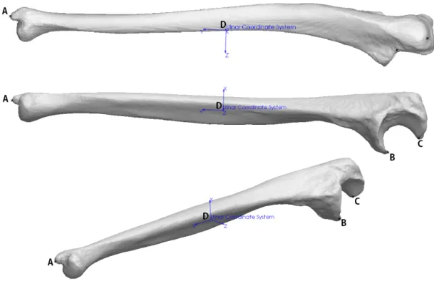
The ulnar coordinate system, XuYuZu, has its origin, Ou, midway along the principle axis of
inertia defined by the center of the dome depression on the distal head and the coronoid process
at the proximal end (Figure 1.13). In the transverse plane this will place Ouat approximately
the center of the diaphysis. For a right arm the Yuaxis points proximally along the longitudinal
axis, the Zu axis points laterally (radially), and the Xu axis points in the volar direction. For
a left arm the Yu axis points distally along the longitudinal axis, the Zu axis points medially
(ulnar), and the Xu axis points dorsally (Appendix A).
Figure 1.13:The construction of an ISB ulnar coordinate system for a left arm. A: Radial Styloid
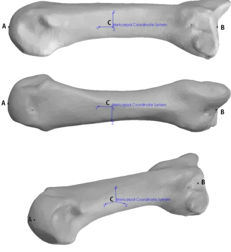
The third metacarpal coordinate system, XmYmZm, has its origin, Om, midway between the
distal and proximal extremities at approximately the center of the diaphysis in the transverse
plane. For a right arm the Ym axis points proximally along the longitudinal axis, the Zm axis
points laterally (radially), and the Xm axis points in the volar direction. For a left arm the Ym
axis points distally along the longitudinal axis, the Zmaxis points medially (ulnar), and the Xm
axis points dorsally (Appendix A).
Figure 1.14: The construction of an ISB metacarpal coordinate system for a left arm. A: Distal
1.6
Methods of Tracking
With ever increasing technology there are a variety of methods currently adopted for measuring
in vitrojoint kinematics of which most predominately include, but are not limited to,
goniome-ters, inertial sensors, image based tracking, electromagnetic tracking, and optical tracking.
1.6.1
Goniometer
Goniometers measure the flexibility of a joint by comparing the angle of two bones relative
to one another using either an over joint or lateral method [32]. The over joint method aligns
the dial to either the inner or outer surface of the joint to measure the angle while the lateral
method places the dial (Figure 1.15) adjacent to the joint with the center or rotation of the dial
aligned with that of the joint [33]. This method allows for a simple means to measure joint
angle forin vitrospecimens since calibration is not required for the instrument. The drawbacks
are that the center of motion for some joints shifts during flexion/extension and the substantial
estimation errors of the position of the joint segments by the operator [34].
1.6.2
Inertial Measurement Units
Inertial measurement units(IMU) are relatively small compared to the other tracking methods
and are composed of accelerometers and gyroscopes to measure translation and rotation for
each of the three axis (Figure 1.16). Through forward kinematics the position of each segment
being tracked may be interpreted from the kinematic information received from each IMU.
This method is excellent for interpreting impact forces and changes in rotational energy of
body segments while being able to estimate change in position. The drawbacks are that the
IMUs are sensitive to drift error due to signal noise which may result in up to approximately 10
to 25 degrees per minute of use if not calibrated correctly [36]. Since the upper extremities of
the human body are modeled as open kinematic chains the results in the motion of a link will
be that of itself as well as every proximal link before it requiring complex equations to deduce
the individual link motion when analyzing multi-linkage systems.
Figure 1.16:A 9DOF digital IMU sensor [red rectangle] with a 3DOF accelerometer to measure
acceleration (ax,ay,az) [left], a 3DOF gyroscope to measure rotation (wx,wy,wz), and a 3DOF
magnetometer to measure magnetic north for a body segment between two points [blue circles]
1.6.3
Image Based Tracking
Image based tracking, or video tracking, is the process of programmatically stitching together
a sequence of images from a video source to recognize and track the motion of an object of
interest between frames and determine the behaviours exhibited [38]. Edge matchingbetween
sequential frames is a technique that detects boundaries of sharp changes in values, otherwise
known as contrast, between adjacent pixels and outlines that region. For instance, a bouncing
white ball in a well-lit black room would provide the best contrast for tracking.
Using this method for tracking human motion becomes a Gaussian problem that uses a
prob-ability distribution of possible relative poses from an image along with a predefined skeletal
model (Figure 1.17) to predict the most likely outcome [39]. The shortfalls of tracking human
motion using a single camera arise from the loss of image depth and scale, reflective
ambigu-ities where multiple poses produce similar images, and lost observations due to occlusions of
limbs during motion [40].
Figure 1.17:Image based tracking attempts to map an object from an image to a known rigid body,
New developments in technology have led to the introduction of the Microsoft Kinect
(Mi-crosoft Corp., WA), which was initially intended as a hands free controller interface for the
Microsoft XBox 360 gaming console that recognizes gestures from the user using two cameras
and an infrared sensor to reconstruct a 3D representation of all objects in the frame of view.
Matching this information to a skeletal model can provide a more accurate estimate of pose and
position of individual body segments that a singular camera could achieve [41]. These methods
are excellent for general motion of limbs for investigating gait, however they are limited by the
assumption of bone positions based on skin markers and are unable to provide any insight to
the kinematics of the underlying skeletal system.
Figure 1.18:Microsoft XBox Kinetic used for mapping the human skeletal model to the user in the
1.6.4
Electromagnetic Tracking Systems
Electromagnetic Tracking Systems (EMTS) are commonly used in invasive surgery as the
method does not require a direct line of sight between the source and sensor [43]. This method
uses induction coils to generate a magnetic field from a tracker which is read by the sensor
to determine the pose and attitude of the tracker. By sequentially activating three coils within
the tracker the sensor can record the disturbance in the surrounding magnetic field to obtain
a 5 DOF reading of the tracker [44]. By introducing multiple trackers to the system each can
effectively become a sensor during their latency period thus increasing the system accuracy
to 6 DOF. The major drawback to this method is that the use of ferromagnetic materials such
as cobalt-chromium and titanium distort the magnetic fields and drastically degrade the
posi-tional accuracy of the system [45]. Special design considerations are needed as convenposi-tional
fasteners and medical tooling may not be used.
Figure 1.19: Electromagnetic sensors induce a magnetic field in three directions (x,y,z) that is
interpreted by a detector for orientation and strength to obtain the estimated position of the trackers
1.6.5
Optical Tracking Systems
Optical tracking systems use an array of at least two infrared cameras Figure 1.20 to triangulate
the global Cartesian coordinates of the markers within the field of view [45]. Passive markers
are commonly spheres or surfaces that reflect infrared light emitted from the camera and are
the more mobile option as there are no wires or power sources required (META Motion).
How-ever, there is error associated with artifacts from other potential unwanted reflective surfaces
in the field of view of the camera which have to be filtered from the data. Passive markers
are relatively large to ensure they are detected by the camera resulting in the system having to
estimate the marker centroid producing a floating center point. Active markers contain light
emitting diodes (LEDs) that emit their own infrared light requiring a power source from either
a battery or the terminal [44]. The intensity of light from an LED allows the point of
recogni-tion to be much smaller than a passive marker lowering the relative error from a floating center.
Furthermore the LEDs can be activated in succession with respect to the other markers to allow
for an ordered marker array which can aid in trouble shooting.
Figure 1.20: An array of cameras may determine the location of infrared LEDs [red circle] that
From the point array obtained by both optical and electromagnetic trackers, the joint motion
can be determined using inverse kinematics to give the pose and attitude of the bones relative
to one another [47]. The Cartesian coordinates of markers can be assigned to specific bones
and important bony landmarks to create relevant body segment coordinate systems within a
computer program to later analyze. Markers defined relative to anatomical landmarks of the
bone assist in joint angle calculations. A stylus is a tracker with a predefined tip length, or rigid
body, assigned to it and is used to digitize landmarks of the bone segments to align the trackers
1.7
Clinical Complications
Wrist pain is a debilitating health issue that can be classified as either mechanical, neurological,
or systemic and can decrease overall quality of life and independence of those affected. It may
be the result from sustaining a traumatic injury or the onset of a degenerative disease [48].
1.7.1
Traumatic Injuries
Upper limb injuries are most commonly the result of a trip or fall where the wrist is extended as
a protective mechanism and may result in bone fractures or injury to ligaments causing sprains
[49, 50]. The most common injury isColles Fracture(Figure 1.21) which occurs at the distal
radius and requires casting, pin fixation, external fixation oropen reduction & internal
fixa-tion to maintain the normal bone position [6, 51, 52]. Soft tissue injuries may sprain or tear
ligaments and in severe cases result in joint dislocations. These injuries may increase laxity
between adjacent bones potentially influencing the range of motion and altering normal carpal
motion.
1.7.2
Degenerative Disease
Degenerative diseases may result from wear and tear or a past injury and can reduce the healthy
layer of articular cartilage present in the joint causing painful bone on bone articulation. In the
event of extreme degradation, wrist fusion may be employed to alleviate pain, however the loss
of wrist motion is functionally disabling. Wrist arthroplasty may be performed to restore wrist
function, however relative to the experience with the hip, knee and shoulder these devices have
a higher failure rate and have yet to be optimized. Hemi-arthroplasty replaces a single side
with the adjacent surface still the native tissue, and a full-arthroplasty replaces the full joint
(Figure 1.22).
Figure 1.22:Total wrist arthroplasty restoring motion to the joint [54]
1.7.3
Bracing Methods
Bracing is commonly used immobilize the joint during a period of recovery after sustaining an
injury or reparative surgery. They are also used in high intensity sports to prevent injury. In
sports, dynamic bracing provides athletes with the required mobility but restricts the motion to
within a specific range while static braces prevent motion entirely. Studies of the effectiveness of current brace designs on controlling wrist motion are needed to optimize these devices to
allow for both rehabilitation and injury prevention. These aforementioned clinical scenarios
often employ laboratory-based testing to determine the motion, stability and loading at the
1.8
Biomechanical Testing & Simulation of Motion Pathways
Understanding wrist kinematics is crucial for advancing surgical methods as it allows for
quan-titative analysis to determine the overall quality of the technique. Alterations of wrist motion
as a result of arthritic disorders or traumatic injuries such as ligament tears, or a fractured bone
result in a decreased quality of life for the effected individual. Methods such as arthroplasty,
soft tissue repairs, and fracture fixation techniques intended to alleviate these wrist
complica-tions must be deemed safe for clinical use before are adopted as a viable option.
New repair techniques may be validated through the use of virtual in-silico computer
simu-lations or physicalin-vitrocadaver models to simulatein-vivoconditions. Both methods have
their associated strengths and weaknesses that will ultimately affect the likelihood of them
be-ing adopted as the primary method of pre-clinical testbe-ing.
Although testing devices and simulations exist to examine the kinematics of the wrist, none
of the published platforms have been able to evaluate wrist motion with the arm in all the
common orientations which occur in normal activities. The conventional approach has been to
place the wrist in a vertical position relative to gravity so that motion mimics an inverted
pen-dulum in neutral forearm rotation which does not encompass the full versatility of the wrist.
To fully validate the functionality of an experimental procedure it should be tested at a range
1.8.1
In-Silico
Simulations
The use of in silico wrist models have the advantage of being relatively inexpensive when
compared toin vitrostudies and provide a high-speed computational platform eliminating the
cumbersome task of monitoring and maintaining an experiment such as wear testing
(Strick-land, 2009). With virtual simulations anatomic specimens are not required, hence they not
deteriorate with prolonged use. Wrist modeling allows for unlimited uses from which one
specimen can encompass an entire array of variations for a single experiment thus
strengthen-ing the comparative results which is not available forin vitroexperiments.
The drawbacks with this method are that soft tissues areviscoelasticin nature and therefore are
difficult to accurately model in CAD software. This results in the creation of simplified models to mimic in vivomotions to achieve comparable results [26]. To validate a virtual model the
results must lie within two standard deviations of the identical physical model to ensure the
accuracy of the results for future studies. Since many assumptions are made during the
cre-ation of a virtual model, there are many variables that may influence the quality of the results.
Therefore, these models must undergo sensitivity testing to ensure that small changes will not
drastically alter the end result of the study.
The wrist joint is combination of complex articulations amongst the carpal bones of which
their exact kinematics during wrist motion is not yet fully documented. The non-linear
defor-mation and strain rate dependent properties of the tendons and ligaments associated with the
wrist result in many assumptions required for modeling that set constants for variables such as
bone density, ligament stiffness, and cartilage properties [55].
With improvements in technology, virtual simulations are rapidly becoming more reliable and
wide spread within the research community but due to their limitations from assumptions and
general unknowns they continue to be less reliable than what is currently achievable usingin
![Figure 1.4: Ligaments of the right wrist and hand for the dorsal [top] and volar [bottom] views showing their origins and insertions [11]](https://thumb-us.123doks.com/thumbv2/123dok_us/7762758.1275000/23.918.166.717.163.682/figure-ligaments-right-wrist-dorsal-showing-origins-insertions.webp)
![Figure 1.5: The joints of the wrist including the distal radioulnar, radiocarpal, intercarpal, and carpometacarpal joints [11]](https://thumb-us.123doks.com/thumbv2/123dok_us/7762758.1275000/25.918.172.731.293.808/figure-joints-including-distal-radioulnar-radiocarpal-intercarpal-carpometacarpal.webp)
![Figure 1.6: Muscles of the right upper extremity for both the volar [left] and dorsal [right] com- com-partments [17]](https://thumb-us.123doks.com/thumbv2/123dok_us/7762758.1275000/27.918.117.814.109.659/figure-muscles-right-upper-extremity-volar-dorsal-partments.webp)
![Figure 1.10: Antagonistic muscle pairs for the elbow; the brachialis activates while the triceps relax to induce elbow flexion [left] and the biceps relax while the triceps activate to induce elbow extension [right] [25]](https://thumb-us.123doks.com/thumbv2/123dok_us/7762758.1275000/33.918.136.770.494.813/figure-antagonistic-brachialis-activates-flexion-triceps-activate-extension.webp)
![Figure 1.20: An array of cameras may determine the location of infrared LEDs [red circle] that can provide the position and orientation of a rigid body in space [46]](https://thumb-us.123doks.com/thumbv2/123dok_us/7762758.1275000/50.918.196.742.594.983/figure-cameras-determine-location-infrared-provide-position-orientation.webp)
![Figure 1.25: Active motion simulator using a manifold of pneumatic actuators acting on 9 muscles of interest to induce motion [51]](https://thumb-us.123doks.com/thumbv2/123dok_us/7762758.1275000/59.918.224.663.277.683/figure-active-motion-simulator-manifold-pneumatic-actuators-muscles.webp)
