IJISET - International Journal of Innovative Science, Engineering & Technology, Vol. 2 Issue 3, March 2015.
www.ijiset.com
ISSN 2348 – 7968
Parametric study of frequency selective surfaces at 5.8GHz using
jerusalem cross for microstrip circular patch antenna
Geeta1, B.R. Dutta2 Dr. Binod.Kr. Kanaujia3
Electronics and communication Department, S.R.M.S.C.E.T, Bareilly ,India
H.O.D of ECE department, Ambedkar Institute of Advanced communication technology & research New Delhi, India
Abstract—In this paper, the parameter which affect the gain and return loss characteristic of the microstrip circular patch antenna, the geometry of the frequency selective surfaces (FSS) elements is the most important one. In this following we study the effect of geometrical parameters of FSS element (W, w, a, l). Here microstrip patch antenna is placed over the layer of FSS. The objective in such design to analyze the return loss, gain and efficiency for microstrip patch antenna which operate at 5.8 GHz.In order to analyze all the parameter of the structure, HFSS software is used. To analyze the reflection coefficient magnitude and phase Ansoft designer software is used.
Keywords—FSS, AMC, PEC, Jerusalem cross, Microstrip patch antenna , Coax-feed method,Return loss,Gain.
I. INTRODUCTION
Recently, with the growing number of wireless applications, therehas been an increasing worldwide interest in low profile, low-cost,wideband system designs. One of the most intrinsic components ofwireless systems is their antenna.Microstrip patch antenna is the natural favorite due to its inherentadvantages of small size, low profile, lightweight, cost-effect, andits ease of integration with other circuits. However, it is well-knowthat a patch antenna on a dielectric substrate may have a verynarrow bandwidth due to surface wave losses. The surface waveexisted on the patch antenna will continue to propagate until itmeets a discontinuity. When the surface wave meets the discontinuity,it may radiate and couple energy to the discontinuity. Thesurface wave will reduce antenna efficiency, gain, and bandwidth.To achieve multi-band and wide-band operation in a patch antennadesign, the frequency selective surface (FSS) is implemented orimbedded in a patch antenna in recent years.FSS has a property that it reflect the plane wave in-phase and suppress the surface wave.FSS can be used as a filter, substrate and superstrate. In this designed FSS is used as a substrate.One of the oldest elements used in FSS work is the Jerusalem cross.Basically it consists of a pair of crossed dipoles with end loading.FSS is based on the resonance.
II. MICROSTRIP PATCH ANTENNA WITH FSS
Fig. 1. Fig.2. This surfac anten which Fig.3. The l as dim of struct w=0. W=8 are th jerusa that w
The unit cell geom
4×4 finite array of
is an array of ces which is u nna.We know t h are loaded w
Circular Patch ant
location of the mensions of JC
the ture.Feedpoint 55mm, leng .5mm,a=4.31m he reference v alem cross elem when an FSS
metry for the JC –
f Jerusalem cross f
f 4×4 Jerusale used as a subst that in Jerusale with small, ortho
tenna over a 4×4 la
feed probe yf C-FSS (w, W, antenna locationisyf=5 gth of the mm, length of
alues for the m ment which op
ground plane
–FSS on AMC
frequency selectiv
em cross frequ trate for the m em cross two cr ogonal section
ayer of FSS
ffor the patch a a, l).Geometri
a on
mm,width o
edge par the cross l=1 microstrip patc perate at 5.8GH is employed,
e surfaces
uency selective microstrip patch rossing dipoles s at their ends.
antenna as wel ical parameters
AMC of the cross rt of cross 1.64mm.These ch antenna and Hz.We observe with the same e h s l s C s s e d e e resonant bandwidt A. Analy The effec FSS elem quantified Wanddec lower fre Fig. 4.Equiv
This is th the fact performa inductanc effective
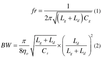
B. Equat
Where L effective frequency of W. Th antenna . frequency After sim return los 5,This is maximum a=4.31mm paramete bandwidt frequency, we th. ytical model ct of changing ment on the an
d. We creasingwthe g
quencies.
valent circuit mod
he circuit mode that Jerusalem ance is the sam ceLgis, eviden capacitance C
tions
BW
Lg is the grid capacitance y by changing here is also eff
.On increasing y will be there.
III. S
mulation it ha ss has been shi the return loss m return loss an
m. In Fig.6, T er of W wh
th is obtained a
e have nearly e
g the geometri ntenna perform
observed t
good matchin
del of JC-FSS unit
el is depicted a m cross is a s me along both
ntly, related gis proportiona
fr
8
g oL
W
d effective in .There is sh (increasing the ffect on return g the value of
.
SIMULATED RES
as been seen t ift than the refe s graph for the
nd bandwidth i This is the re hich the max
at 5.8GHz for W
ISSN
equal to 67%
calparameters mance was ou that on ng characterist
cell
along oneaxis. symmetric sha h axis. the gri
to l andwwh al to W and a.
1
2
L
gL
g d gL
L
C
L
nductanceand hift down in e width of strip loss and the g f w, increase iSULTS
that resonant ference parame parameter of a is obtained at 5 eturn loss grap ximum return W=8.5mm. In
N 2348 – 7968
increase in
of the JC- utlined and increasing tics shiftto
It is due to apeand the d effective hereas the
d gL C
(1) 2 d dL
L
(2)Cg is the n resonant p) the value
gain of the in resonant
frequency, eter . In Fig a which the 5.8GHz for ph for the
IJISET - International Journal of Innovative Science, Engineering & Technology, Vol. 2 Issue 3, March 2015.
www.ijiset.com
ISSN 2348 – 7968
is the return loss graph for the parameter of l which the maximum return loss and bandwidth is obtained at 5.8GHz for l=11.64mm.In Fig.8, This is the return loss graph for the parameter of w which the maximum return loss and bandwidth is obtained at 5.8GHz for w=.55mm. This is the return loss graph for the parameter of a which the maximum return loss and bandwidth is obtained at 5.8GHz for a=4.31mm.In Fig.9, This is the return loss graph for all the parameter (W,a,l,w) which the maximum return loss and bandwidth is obtained at 5.8GHz.In Fig.10, this is the graph of radiation efficiency which shows the 85% efficiency for entire bandwidth. In Fig.11,this is the plot of 2D radiation pattern which shows the maximum gain is 8dB at 5.8GHz .
Fig.5. The graph shows the return loss and resonant frequency for ‘a’
Fig.6. The graph shows the return loss and resonant frequency for ‘W’
Fig.7. The graph shows the return loss and resonant frequency for ‘l’
Fig.8. The graph shows the return loss and resonant frequency for ‘w’
Fig.9. The graph shows the return loss and resonant frequency for (W,w,a,l)
Fig.10. The graph shows the radiation efficiency of the antenna
4.50 5.00 5.50 6.00 6.50 7.00
Freq [GHz] -37.50
-25.00 -12.50 0.00
Y1
HFSSDesign1
XY Plot 3 ANSOFT
m1
m2 m3
Curve Info a=3.1 Imported
a=5.31 Imported
a=4.31 Imported
Name X Y
m1 5.5200 -26.8382
m2 5.7200 -36.9835
m3 5.9600 -21.9115
4.50 5.00 5.50 6.00 6.50 7.00 Freq [GHz]
-35.00 -30.00 -25.00 -20.00 -15.00 -10.00 -5.00 0.00
Y1
HFSSDesign1
XY Plot 3 ANSOFT
m1 m2
Curve Info W=7.5 Imported
W=8.5 Imported Name X Y
m1 5.8500 -32.5463
m2 5.5100 -26.0671
4.50 5.00 5.50 6.00 6.50 7.00
Freq [GHz] -35.00
-30.00 -25.00 -20.00 -15.00 -10.00 -5.00 0.00
Y1
HFSSDesign1
XY Plot 3 ANSOFT
m1 m2
Curve Info l=11.64 Imported
l=9.64 Imported Name X Y
m1 5.8500 -32.5463
m2 5.5100 -26.0671
4.50 5.00 5.50 6.00 6.50 7.00
Freq [GHz] -35.00
-30.00 -25.00 -20.00 -15.00 -10.00 -5.00 0.00
Y1
HFSSDesign1
XY Plot 3 ANSOFT
m1 m2
Curve Info w =0.55 Imported
w =0.45 Imported
Name X Y
m1 5.8500 -33.3024
m2 5.8750 -31.4693
4.50 5.00 5.50 6.00 6.50 7.00 Freq [GHz]
-35.00 -30.00 -25.00 -20.00 -15.00 -10.00 -5.00 0.00
d
B
(S
(1
,1
))
HFSSDesign1
XY Plot 3 ANSOFT
m1
Curve Info dB(S(1,1)) Imported Name X Y
ISSN 2348 – 7968
The table I shows thecharacteristic of circular patch antenna which operate at 5.8GHz frequency its gain is 8dB ,Bandwidth is 1GHz , efficiency is 99.30% and return loss is -32.546dB.
TABLE I
Characteristic My results at 5.8GHz
Gain 8dB Bandwidth 1GHz Efficiency 99.30% Return loss -32.546dB
Resonant frequency 5.8GHz
C
ONCLUSIONIn this paper a novel design of artifcial magnetic conductor substratefor bandwidth enhancement of patch antenna and the analysis of varying the parameter of the element of jerusalem cross on the gain, return loss, front-to-back ratio and resonant frequency is analyzed.Makinguse of the High Impedance Surfaces, mutual coupling between the antenna and its image is reduced dramatically which results is easy impedance matchingover a relatively wide bandwidth as well as total power reflection thatcreates the desired front-to-back ratio. The structure of microstrip patch antenna is implanted over the FSS which operate at 5.8GHz as a reference frequency by which we compare the shift of all the value or antenna parameters. Artificial Magnetic Conductor (AMC) Antenna design hasbeen derived using the IWO invasive weedoptimizationwith a view to improve the bandwidth.
Acknowledgment
The Authors express their appreciation to Mr. R. Raja, Senior Engineer, Innovent Engineering Solution Pvt. Ltd., and Mr. Sovanmohanty, Asst.Professor of Department of Electronics and Communication , Shri Ram Murti College of Engg. &Technology (S.RM.S.C.E.T), Bareilly (U.P) for their technical support and valuable advices by which we overcome the errors in simulation of our design and suggest us the right path to proceed.I would like to express my deep and sincere gratitude to all the faculty members of Electronics and
communication Department, for giving us their valuable support to overcome all the huddleswhich come in our designing. We also thanks our college SRMSCET, Bareilly as they provides us the HFSS plate form with help of which we simulate our design and get the result, and also provide the needful help in all area of designing .In last we also thanks Roger’s Cooperation for providing us the dielectric material Roger’s RT duroid 6002.
References
[1]F. Yang and Y. Rahmat-Samii, “Reflection phase characterizations of theEBG ground plane for low profile wire antenna applications,” IEEE Trans. Antennas Propag., vol. 51, no. 10, pp. 2691–2703, Oct. 2003.
[2]J. Liang and H. Y. David Yang, “Radiation characteristics of a microstrip patch over an electromagnetic bandgap surface,” IEEE Trans.AntennasPropag., vol. 55, no. 6, pp. 1691–1697, Jun. 2007. [3]D. Sievenpiper, L. Zhang, R. F. Jimenez Broas, N. G. Alex’opolous,
and E. Yablonovitch, “High-impedance electromagnetic surfaces with a forbidden frequency band,” IEEE Trans. Microwave Theory Tech., vol. 47, no. 11, pp. 2059–2074, Nov. 1999.
[4]X. L. Bao, G. Ruvio, M. J. Ammann, and M. John, “A novel GPS patch antenna on a fractal hi-impedance surface substrate,” IEEE AntennasWirelessPropag. Lett., vol. 5, pp. 323–326, 2006. [5]H. Mosallaei and K. Sarabandi, “Antenna miniaturization and
bandwidth enhancement using a reactive impedance substrate,”
IEEE Trans.AntennasPropag., vol. 52, no. 9, pp. 2403–2414, Sep. 2004.
[6] A. P. Feresidis, G. Goussetis, S. Wang, and J. C. Vardaxoglou, “Artificialmagnetic conductor surfaces and their application to low-profile high-gain planar antennas,” IEEE Trans. Antennas Propag., vol. 53, no. 1, pp. 209–215, Jan. 2005.
[7]B. A. Munk, R. J. Luebbers, and R. D. Fulton, “ Transmission through a 2-layer array of loaded slots,” IEEE Trans. Antennas Propag., vol. AP22, no. 6, pp. 804–809, Nov. 1974.
[8] B. A. Munk, Frequency Selective Surfaces—Theory and Design. New York: Wiley, 2000.
[9] F. R. Yang, K. P. Ma, Y. Qian, and T. Itoh, “A uniplanar compact photonic- bandgap (UC-PBG) structure and its applications for microwave circuits,” IEEE Trans. Microwave Theory Tech., vol. 47, no. 8, pp. 1509–1514, Aug. 1999.
[10]C. N. Chiu, C. H. Kuo, and M. S. Lin, “Bandpass shielding enclosure design using multipole-slot arrays for modern portable digital devices,” IEEE Trans. Electromagn. Compat., vol. 50, no. 4, pp. 895–904, Nov. 2008.
[11]M. S. Zhang, Y. S. Li, C. Jia, and L. P. Li, “Signal integrity analysis of the traces in electromagnetic-bandgap structure in high-speed printed circuit boards and packages,” IEEE Trans. Microwave Theory Tech., vol. 55, no. 5, pp. 1054–1062, Nov. 2007.
[12] T. K. Wu and S. W. Lee, “Multiband frequency selective surface with multiring patch elements,” IEEE Trans. Antennas Propag., vol. 42, no. 11, pp. 1484–1490, Nov. 1994.
[13]G. I. Kiani, K. L. Ford, K. P. Esselle, A. R. Weily, C. Panagamuwa, and J. C. Batchelor, “Single-layer bandpass active frequency selective surface,” Microw. Opt. Technol. Lett., vol. 50, no. 8, pp. 2149–2151, Aug. 2008.
[14] G. I. Kiani, K. L. Ford, K. P. Esselle, A. R. Weily, and C. J. Panagamuwa, “Oblique incidence performance of a novel frequency selectivesurface absorber,” IEEE Trans. Antennas Propag., vol. 55, no. 10, pp. 2931–2934, Oct. 2007.
IJISET - International Journal of Innovative Science, Engineering & Technology, Vol. 2 Issue 3, March 2015.
www.ijiset.com
ISSN 2348 – 7968
[16] A. K. Zadeh and A. Karlsson, “Capacitive circuit method for fast and efficient design of wideband radar absorbers,” IEEE Trans. AntennasPropag., vol. 57, no. 8, pp. 2307–2314, Aug. 2009. [17]R. Ulrich, “Far-infrared properties of metallic mesh and its
complementary structure,” Infrared Phys., vol. 7, no. 1, pp. 37–50, 1967.
[18] N. Engheta and R. W. Ziolkowski, Metamaterials: Physics and Engineering Explorations. Hoboken/Piscataway, NJ: Wiley-IEEE Press,2006.
[19]D. J. Kern, D. H. Werner, A. Monorchio, L. Lanuzza, and M. J. Wilhelm,“The design synthesis of multiband artificial magnetic conductors using high impedance frequency selective surfaces,”
IEEE Trans.AntennasPropag., vol. 53, no. 1, pp. 8–17, Jan. 2005. [20] J. McVay, N. Engheta, and A. Hoorfar, “High impedance
metamaterialsurfaces using Hilbert-curve inclusions,” IEEE Microw. WirelessCompon. Lett., vol. 14, pp. 130–132, 2004. [21] J. Bell and M. Iskander, “ A low-profile archimedean spiral
antennausing an EBG ground plane,” IEEE Antennas Wireless Propag. Lett., vol. 3, pp. 223–226, 2004.