International Journal of Research (IJR) Vol-1, Issue-10 November 2014
ISSN 2348-6848
Speed Control of DC Motor
USING P-I, I-P, ANDFUZZY
CONTROLLER
Ms. Priya Yadav, Salma Khan, Yogesh Chauhan, Sandeep Chauhan
Dronacharya college of engineering, Gurgaon
Priya.yadav@ggnindia.dronacharya.info
Abstract
:
The purpous of this paper is to obtain the simulation results on a dc motor control system with a basic Fuzzy logic controller (FLC). IN this era the need for electric driven vehicle has increasing rapidly due to the global warming problem. The traditional Proportional-Integral (P - I) controller, which has been widely used for the speed control of dc motor drives, has been compared with the relatively new
Integral-Proportional (I-P) controller which first
discussed in the year of 1978. P-I controller is used to control the speed of DC Motor. A model
is developed and simulated using
MATLAB/SIMULINK. However, the P-I
controller has some disadvantages such as: the high starting overshoot, sensitivity to controller gains and sluggish response due to sudden disturbance. So, the relatively new Integral-Proportional (I-P) controller is proposed to overcome the disadvantages of the P-I controller. This paper presents some improvements in this important field of industries. The result of
simulation and experimental indicate the
superiority of (I-P ) controller over (P-I ) controller. The proposed controller results in reduced oscillations around the set point which are present in system with a basic fuzzy logic controller.I-P and P-I both are using widely in this decade.
Keywords:
DC motor drive, speed control; Integral- Proportional I-P controller; Proportional-Integral P-I controller; Fuzzy logic controller
INTRODUCTION
Because of their high reliabilities, flexibilities and low costs, DC motors are widely used in industrial applications, robot manipulators and
home appliances where speed and position control of motor are required. PID controllers are commonly used for motor control applications because of their simple structures and intuitionally comprehensible control algorithm. These Conventional dc motors are highly efficient and their characteristics make them suitable as servomotor. However, its needs a commutator and brushes which are subject to wear and required maintenance. The functions of commutator and brushes were implemented by solid-state switches that can realize maintenance-free motors. These motors are now known as brushless dc motors. Brushless dc motors are widely used in various applications. Two examples of them are electric vehicle and industrial machinery. Fuzzy logic controller (FLC) which is presented by Zadeh in 1965, is a new controller [1]. Besides that, FLC is more efficient from the other controller such as P-I controller. The comparison between them is needed to compare what the controller is efficient [2]. The reason why conventional controller low efficiency such as P-I controller because the overshoot is too high from the set point and it may takes delay time to get constant and sluggish response due to sudden change in load torque and the sensitivity to controller.
II. MATHEMATICAL MODELLING
International Journal of Research (IJR) Vol-1, Issue-10 November 2014
ISSN 2348-6848
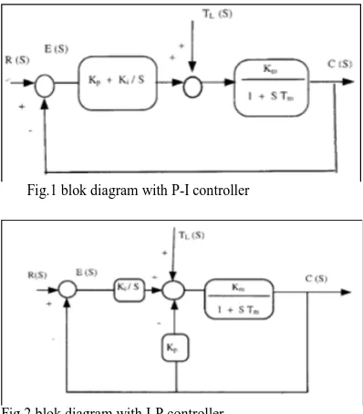
feedback path and it actslike feedback compensation. The analysis in S- domain is discussed in this section to study the transient and thesteady-state behaviour for both controllers
Fig.1 blok diagram with P-I controller
Fig.2 blok diagram with I-P controller
A. P - I Controller
The closed loop transfer function between the output C(S) and the input R(S) is given in (1).
Where Ki and Kp, are the integral and the proportional gains of P-I or I-P controller, Tm, is the mechanical time constant of motor, and Km, is the motor gain constant. The transfer function between the output C(S) and the load torque disturbance TL(S) is given in (2).
I-P CONTROLLER
The closed loop transfer function between the output C (S) and the input R (S) is given in (3).
From (1) and (3), P-I and I-P controllers have the same characteristic equations, and it can be seen that the zero introduced by the P-I controller is absent in the case of the IP controller. Therefore the overshoot in the speed, for a step change in the input reference R (S) is expected to be smaller for the I-P control.
III. SPEED CONTROL SYSTEM USING A BASIC FUZZY LOGIC CONTROLLER
The block diagram of the dc motor control system with a basic FLC is shown in Fig. 3. The basic FLC consists of the following four blocks [6]:
Fuzzifier which converts input data (error and error
rate) into suitable linguistic values.
Knowledge base which consists of a data base with necessary linguistic definitions (rule set).
Defuzzifier which produces a non-fuzzy control action that represents the membership function of an inferred fuzzy control action.
• Decision making logic which is used to decide what control action should be taken.
•Defuzzification is done using the Center-of-gravity method in which the inferred (numerical)
value of the
where mi are the singletons and Ti are the corresponding degree of fulfilment.
The output of the controller is the change in motor voltage
International Journal of Research (IJR) Vol-1, Issue-10 November 2014
ISSN 2348-6848
State space model
where all the variables are well known. The damping ratio 6 of a second order system is expressed in terms of the maximum overshoot M, as
Fig.3 basic function of fuzzy logic controller
Set of inguistic variable
Fig 5. Rule base used in the design of the FLC
IV. SIMULATION AND RESULTS
A. P-I Controller
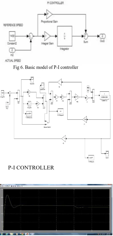
The speed and torque of an induction motor is control by P-I controller. PI controller gets one input. The actual speed and reference speed are
compared and the error of the speed is given as input to PI controller. Based on the proportional gain value and the integral gain value, the PIcontroller regulates an output which is given to the inverter triggering switch depending on the load variation.
Fig 6. Basic model of P-I controller
P-I CONTROLLER
Fig 8. Simulation Result Of PI Simulink Model
B. Simulink Model of IP Controller
International Journal of Research (IJR) Vol-1, Issue-10 November 2014
ISSN 2348-6848
Fig 8. Simulation Result Of IP Simulink Model
C. Fuzzy Logic Controller
Fuzzy logic control (FLC) is a control algorithm based on a linguistic control strategy which tries to account the human’s knowledge about how to control a system without requiring a mathematical model [6,7]. The approach of the basic structure of the fuzzy logic controller system is illustrated in FIG. 9
Fig 9. Structure of Fuzzy Logic Controller
Input and output are non-fuzzy values and the basic configuration of FLC is featured in Fig10. In the system presented in this study, Mamdani type of fuzzy logic is used for speed controller. Inputs for Fuzzy Logic controller are the speed error (e) and change of speed error. Speed error is calculated with comparison between reference speed, ω ref and the actual speed, ω act .
Fig 10. Block Diagram of FLC
Fig 11. Simulink model of FUZZY Controller
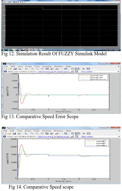
Fig 12. Simulation Result Of FUZZY Simulink Model
Fig 13. Comparative Speed Error Scope
Fig 14. Comparative Speed scope
V. CONCLUSION
International Journal of Research (IJR) Vol-1, Issue-10 November 2014
ISSN 2348-6848
can replace P-I for the speed control of dc motor drives. The simulation results obtained on a dc motor speed control system using a fuzzy logic controller are presented in the paper. The system uses a basic FLC as well as an improved FLC in which an error interpreter is included. It is seen that the step response with error interpreter has a smaller rise time and a reduced overshoot.
REFRENCES