ISSN: 2319-8753
International Journal of Innovative Research in Science,
Engineering and Technology
(An ISO 3297: 2007 Certified Organization)
Vol. 3, Issue 5, May 2014
Design and Simulation of a Fuzzy Non Linear
PI Controller for Dc-Dc Buck Converter for
Low Steady State Deviations and Its
Performance Comparison with PI Controller
R. Ganesan 1, S. Vignesh 2Associate Professor, Department of Electrical and Electronics Engineering, Oxford Engineering College, Pirattiyur,
Trichy – 620 009, Tamil Nadu, India1
Assistant Professor, Department of Electrical and Electronics Engineering, Oxford Engineering College, Pirattiyur,
Trichy – 620 009, Tamil Nadu, India 2
Abstract: DC- DC converter plays an important role in power conversion. They are used in many applications like
computer power supplies, switching mode regulators etc. Control action of buck converters involves maintaining constant output voltage in the presence of change in load and change in supply voltage conditions. Traditional controllers like PID controllers have limitation in control action whenever the changes are rapid in nature. Fuzzy controllers described by linguistic variables can be employed for buck converter output voltage control. Fuzzy controller can be used as stand alone or in conjunction with PI controller for buck converter output control. In this paper design and simulation using MATLAB/SIMULINK of buck converter output voltage using fuzzy logic control is presented. Simulation results are presented to prove that the steady state deviations of fuzzy PI controller are minimum.
Keywords:Buck converter, PI control, fuzzy control, MATLAB-SIMULINK.
I. INTRODUCTION
The buck converter is a dc-dc converter that is used for stepping down dc voltage level. They are used for mother board supplies in personal computers. They use power electronics switches that can be made on or off to maintain a specified output voltage level. The essence of control action is to maintain desired voltage level in the presence of load side disturbances (load change) and supply side disturbances (input voltage variations). Traditional PID control is employed for buck converter control action. But the control action is subject to component ageing, poor transient response, long settling time and instability in the presence of severe disturbances. Fuzzy controllers are defined by linguistic variables. As such their control action is independent of component ageing. Earlier methods centred around isolation of state variables for feedback control [1]. Uran et al. proposed feedback loop control [2]. Linear Quadratic Controller (LQR) was proposed to improve control action [3]-[4]. Lee C. C. has dwelled upon the application of fuzzy logic control to many control actions [5]. Fuzzy control being a non linear control is independent of measurement and noise error. In addition fuzzy control is adaptable by redefining membership fuctions. This paper is organized as follows: section 2 describes buck converter circuit and its modeling, section 3 describes fuzzy logic controllers, section 4 describes proposed buck converter control section 5 simulation results and section 6 conclusions.
II. BUCK CONVERTER CIRCUIT
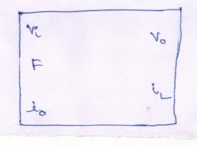
Fig. 1 Buck converter circuit
There are three states of the circuit:
(i) Switch S on, Diode D off; (ii) Switch S off, Diode D on; (iii) Switch S off, Diode D off.
Switch S is controlled by pulse width modulation (PWM) technique. In this, a saw tooth voltage is compared with a fixed dc voltage and if saw tooth voltage is lower than the fixed dc voltage then switch S is closed or else switch S is open.
The equations for buck converter are presented as below: [7]
Entire buck converter is modeled as Matlab Simulink block with Vi,Io, F as input variables and Vo, IL as output variables as shown in Fig. 2. F is the gate signal.
ISSN: 2319-8753
International Journal of Innovative Research in Science,
Engineering and Technology
(An ISO 3297: 2007 Certified Organization)
Vol. 3, Issue 5, May 2014
III.FUZZY LOGIC CONTROLLER
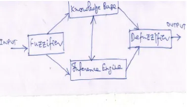
In 1965, Zadeh proposed fuzzy logic. A simple block diagram of fuzzy controller is shown in Fig. 3.
Fig. 3 Fuzzy Control System
Four major units of fuzzy controller are: fuzzification block, fuzzy knowledge base, fuzzy inference engine and defuzzification block [8]. Fuzzification block measures, scales and converts the input into a set of linguistic variables. Fuzzy knowledge base contain fuzzy rule which are in the form of IF---THEN linguistic statements. Fuzzy inference engine is an important block by which fuzzy logic controller mimic human intelligence in decision making. Defuzzification block converts fuzzy control actions into crisp signals.
IV.CONTROLLER FOR BUCK CONVERTER
The buck converter parameters are given in Table 1.
Table 1 Buck converter parameters
Parameter Value
Input voltage 12 V
Output voltage 5 V
Inductor value 300 μH
Capacitor value 5 μF
PWM frequency 50 kHz
Fig. 4 Fuzzy logic controller membership functions
The rule base is presented as follows: If input is mf1 then output is mf1 If input is mf2 then output is mf2 If input is mf3 then output is mf3
V. SIMULATION RESULTS
ISSN: 2319-8753
International Journal of Innovative Research in Science,
Engineering and Technology
(An ISO 3297: 2007 Certified Organization)
Vol. 3, Issue 5, May 2014
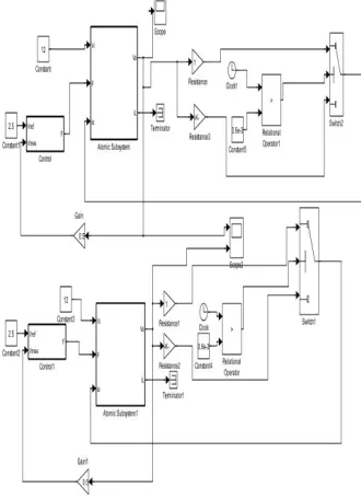
frequency to generate PWM signals. The fuzzy controller along with PI is shown in Fig. 6. In fuzzy controller block, the error signal is applied first to membership block. The output of the fuzzy block is given to PI controller. PI controller output is given to PWM block to generate switching signals.
Fig. 6 Fuzzy controller with PI
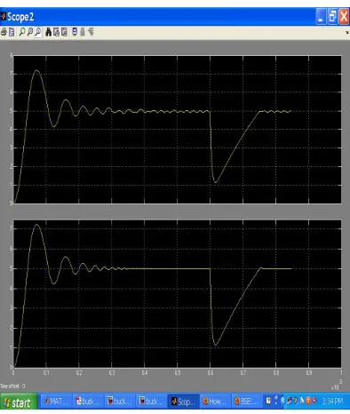
In the simulation circuit, at 0.6ms the load was changed from R= 1ohms to R=8 ohms. Still the buck converter was able to maintain its output voltage. Fig. 7 presents the simulation results. The upper graph shows the simulation of the buck converter with PI controller and the lower graphs shows simulation with fuzzy controller. From the figure, we can infer that fuzzy controller is able to maintain its output voltage at 5V with minimal steady state deviation than PI controller.
Fig. 7 MATLAB Simulink Simulation of buck converter with PI fuzzy controller
VI Conclusion
In this research paper buck converter controller using PI controller was studied first. Application of fuzzy logic to output voltage error and fuzzy inference of output voltage error was applied to conventional PI block gain Kp and Ki. This greatly improved the steady state error of buck converter output voltage. Finally the simulation results of both converters were compared. From the simulation results it is concluded that application of fuzzy logic to PI controller is an option when tight steady state deviations are needed as in the case of PC power supply.
ACKNOWLEDGMENT
First author wishes to thank his friend Dr. P.S. Srinivasan, Former Dean/EEE, SASTRA University for all his help.
REFERENCES
[1] Kostov, K. S., Kyyra, J., Suntio, T., The input impedance of a buck converter, European power Electronics Conf., 2003.
Lasea, I. G. D., Myrzik, J. M. A., State- space control structures for buck converters with /without Input Filter, IEEE. 2005,Power Electron, European Conf., 2005.
[2] Uran, S., Milanovic, M., State controller for buck converer, EUROCON, 2003., vol. 1, 381–385, 2003.
[3] Dores Costa, J. m., Design of linear quadratic regulators for quasi- resonant dc-dc converter, IEEE. 2001. Power Electron Conf., PESC 2001.
vol. 1, 422 – 426, 2001.
[4] Leung, F. H. F., Tam, P. K. S., Li, C. K., The control of switching dc-dc converter S-A general LQR problem, IEEE Trans., Ind Electron., vol. 38, 65-71, 1991.
ISSN: 2319-8753
International Journal of Innovative Research in Science,
Engineering and Technology
(An ISO 3297: 2007 Certified Organization)
Vol. 3, Issue 5, May 2014
[8] Cetin Elmas a, Omer Deperlioglu , Hasan Huseyin Sayan, Adaptive fuzzy logic controller for DC–DC converters Expert Systems with Applications, 36 (2009), pp. 1540–1548
[9] So, W. C., Tse, C. K., & Lee, Y. S. A fuzzy logic controller for DC–DC converter. In IEEE power electronics specialists conference records 1994 , pp. 315–320.
[10] Ned Mohan, T.M. Undeland and W.P. Robbins, Power electronics, converters application, and design, John Wiley and sons, third edition, 2010.
[11] M.H. Rashid, ,Power electronics circuits, devices and application third edition, Pearson education, 2012. [12] Terano, T., AsaI, K., Sugeno, M., Applied fuzzy systems, Academic Presss Inc., pp.86-93, 1994.
Biography
R. Ganesan was born in India in 1970. He received his B.E. and M.Tech.degree from
Alagappa Chettiar College of Engineering and Technology, Karaikudi and IIT, Kanpur respectively. He worked as Assistant Project Engineer (Electrical) at The Fertilizer Corporation of India Limited, A Government of India Undertaking. Presently he is working as Professor and HOD/EEE at Oxford Engineering College, Pirattiyur, Trichy – 620 009.
S. Vignesh was born in India in 1989. He received his B.E.degree from Saranathan