Division X
SEISMIC SOIL-STRUCTURE INTERACTION ANALYSIS OF DEEPLY
EMBEDDED SMRs AND ASSOCIATED CHALLENGES
Sunwoo Park1 and Sujit Samaddar2
1 Structural Engineer, Office of New Reactors, U.S. Nuclear Regulatory Commission, USA
2 Chief, Structural Engineering Branch, Office of New Reactors, U.S. Nuclear Regulatory Commission,
USA
ABSTRACT
Many small modular reactors (SMRs) that are being considered in the United States are deeply embedded in the ground, which requires additional technical considerations in determining seismic demands compared to the traditional, shallow-embedded light water reactors (LWRs). One such challenge would be determining the hazard-consistent seismic input for the site response and soil structure interaction (SSI) analysis. A typical SSI analysis of a nuclear power plant structure is performed deterministically involving three bounding soil columns developed from a statistical treatment of fully randomized soil column properties used in the site response analysis. For shallow embedded structures, regulatory guidance is developed to ensure that the hazard-consistent seismic input is used for the site response and SSI analysis. A critical element in this process is a verification that the foundation input motions for the SSI analysis with deterministic soil columns adequately bound the performance-based spectra at the surface. For deeply embedded structures, a similar process but with additional locations of verification would be needed to ensure that the seismic input motions and deterministic soil columns adequately capture the seismic environment and subsurface conditions considered in the site response analysis. The paper presents relevant background, rationale and some illustrations to these technical issues and discusses relevant guidance provided in the Design-Specific Review Standard (DSRS) for an SMR design.
INTRODUCTION
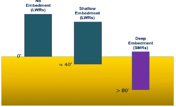
The nuclear power plant structures, systems, and components (SSCs) important to safety must be designed to withstand the effects of the Safe Shutdown Earthquake ground motion. The design evaluation of these SSCs should take into account seismic soil-structure interaction (SSI) effects. The established SSI analysis methodologies are used primarily for the current generation of large LWRs whose structures are founded on or near the ground surface. Influenced by benefits such as enhanced protection from missiles and aircraft impact and potential reduction in seismic demands, several SMR designs propose to bury or deeply embed major plant structures below grade, which presents new technical challenges with respect to the seismic design and analysis of these structures. Figure 1 illustrates typical embedment depths for large LWRs and SMRs. In this paper, some key technical issues pertaining to the seismic SSI analysis of deeply embedded nuclear structures are addressed and related guidance provided in the recent DSRS for an SMR design is illustrated.
SEISMIC SOIL-STRUCTURE INTERACTION
due to kinematic constraint between the embedded structure and surrounding soils and is dictated by their stiffness and geometry including the embedment depth, whereas the inertial interaction is primarily influenced by the mass of the superstructure. Therefore, for a deeply embedded structure, one may expect more pronounced kinematic interaction effect and less inertial interaction compared to a shallow embedded structure.
A seismic SSI analysis, following the substructure approach, involves three major components; site response problem, impedance problem, and structural problem, as illustrated in Equation (1) (Ref. 1),
where C’s denote the complex stiffness matrices for the structure and excavated soil volume and u’s the displacement vectors for the superstructure and foundation. Equation (1) indicates that the forcing functions on the right-hand side are determined as the product of the foundation impedance matrix (Xff) and free-field
motions (uf’) at the “interaction” nodes. The interaction nodes in an SSI problem connect the excavated soil
volume to the free field, and an accurate determination of the impedance functions and free-field motions at these interaction nodes are an important step in the SSI analysis.
The site-specific seismic hazard at the base rock is represented by its Uniform Hazard Response Spectra (UHRS) which can be transferred to the foundation level (Foundation Input Response Spectra, FIRS) or to the ground surface (Performance Based Surface Response Spectra, PBSRS) through site response analyses and following the performance-based procedure. The site response analysis uses a probabilistic approach typically involving 60+ randomized soil profiles in order to account for the variability of soil profiles and properties. However, the SSI analysis typically uses a deterministic approach involving three bounding soil columns - Best Estimate (BE), Upper Bound (UB), and Lower Bound (LB), which correspond respectively to the mean, and mean plus and minus standard deviation of the 60+ randomized soil column properties.
The SSI analysis procedure first determines the free-field motions at interaction nodes to establish the forcing functions (or seismic loads). Currently, it may be ideal but not necessarily practical to run SSI analysis probabilistically due to the prohibitive computational resource demand. Incompatibility between the approaches taken by the site response analysis (probabilistic) and SSI analysis (deterministic) necessitates the development of guidance to ensure conservatism in the SSI analysis for seismic demand
Figure 1. Nuclear reactors with varying embedment depths
calculations. To address such need, U. S. Nuclear Regulatory Commission (NRC) issued in 2010 an Interim Staff Guidance “On Ensuring Hazard-Consistent Seismic Input for Site Response and Soil Structure Interaction Analyses” (DC/COL-ISG-017, Ref. 2).
HAZARD-CONSISTENT SEISMIC INPUT
When a site-specific SSI analysis is conducted, the seismic input consistent with the seismic hazards at the site should be determined, and DC/COL-ISG-017 provides two approaches to obtain the hazard-consistent seismic input for the SSI analysis. One such approach is based on information provided in the NEI white paper (Ref. 3) and an important element in this approach is a verification that input seismic motions used for the SSI analysis model for the three deterministic soil conditions (LB/BE/UB) adequately bound the PBSRS in both the horizontal and vertical directions at the surface, and the verification process is often referred to as the “NEI Check”.
Figure 2 illustrates the process involved in the NEI check. The left hand side of the figure illustrates that the FIRS and PBSRS are obtained by transferring UHRS at the base rock to the foundation and ground surface, respectively, through probabilistic site response analysis involving 60+ randomized soil columns. It is to be noted that the performance-based procedure in accordance with RG 1.208 (Ref. 4) is also included in this process so that the resulting FIRS and PBSRS achieve the target performance goal that ensures the performance of the safety-related SSCs is acceptable. The FIRS and PBSRS are defined as free-field outcrop response spectra. The right hand side of the figure illustrates that the FIRS input motions are transferred through three deterministic soil columns (LB/BE/UB) to determine the free-field motions at interaction nodes used in Equation (1). The free-field motions obtained by transferring the FIRS through the three deterministic soil columns may not necessarily be conservative when compared to their performance-based counterparts based in the probabilistic site response analyses involving 60+ soil columns. The NEI Check is performed to ensure that the deterministic soil columns and associated input motions used in the SSI analysis are adequate and provide conservatism in seismic demand calculations for the safety-related SSCs.
The NEI Check involves a multi-step process: (1) develop input motions compatible with the FIRS at the foundation level, (2) transfer the FIRS input motions to the surface through three deterministic soil columns (LB/BE/UB), (3) check if the PBSRS is bounded by the envelope of the three FIRS-based surface response spectra, (4) if the PBSRS is bounded, the FIRS input motions and the three bounding soil columns can be used for the SSI analysis; if not, add soil columns or modify the FIRS input motion time histories so that the resulting surface response spectra envelope bounds the PBSRS. More details on the NEI Check are available in the NEI white paper referenced above (Ref. 3).
AN EXAMPLE FROM LWR LICENSING
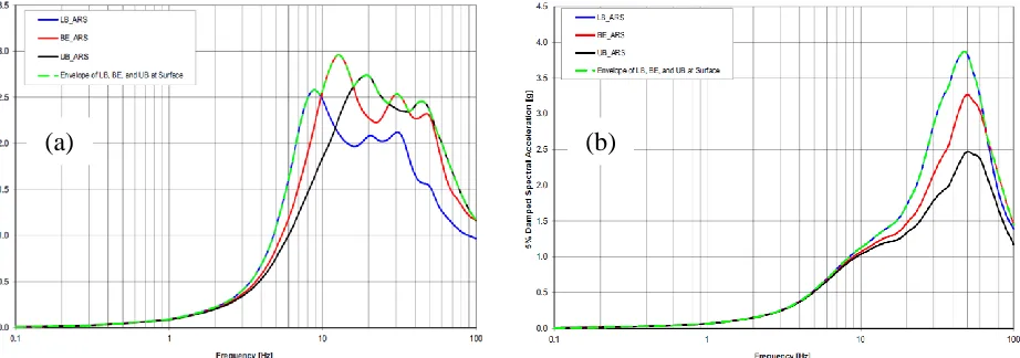
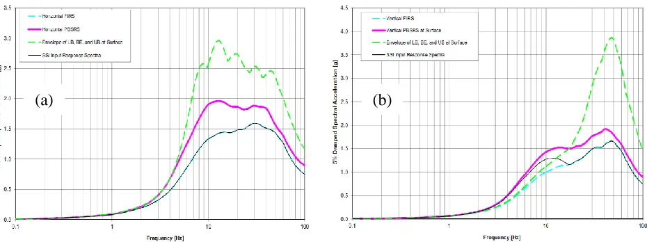
For an illustration of the NEI Check applied to a shallow embedded nuclear structure, an example from a recent large LWR license application (Ref. 5) which is publically accessible through the NRC Agencywide Documents Access and Management System (ADAMS) is presented here. The Control Building at the proposed North Anna Unit 3 site is a seismic Category I structure and is embedded approximately 15m (50 feet) into the ground. Figure 3 shows the strain-compatible shear wave velocities for the three deterministic soil columns used in the site-specific SSI analysis of the Control Building. Figures 4(a) and (b) show the acceleration response spectra (ARS) at the surface obtained by transferring the FIRS input motions through the three deterministic soil columns (LB/BE/UB) and their envelope for the horizontal and vertical directions, respectively. Figures 5(a) and (b) show the FIRS, PBSRS, and the ARS envelope at the surface for the horizontal and vertical directions, respectively.
For the horizontal motion, the PBSRS is practically bounded by the envelope of surface
ARS and therefore no adjustment is needed for the FIRS to be used as SSI input motions. However, for the vertical motion, the PBSRS is not bounded by the envelope of surface ARS and adjustment is needed. The FIRS is adjusted by the ratio of the PBSRS to the envelope of surface ARS at each frequency for the frequency range of 2 Hz to 15 Hz with the maximum adjustment factor being 1.39. The adjusted FIRS are referred to as the SSI input response spectra in Figures 5(a) and (b). The adjusted FIRS (or SSI input response spectra) together with the three bounding soil columns are used in SSI analyses to determine the site-specific seismic demands which, in combination with other loads, are used in structural design evaluation of the Control Building for the North Anna Unit 3 site.
(a)
(b)
Figure 4. FIRS-based acceleration response spectra (LB/BE/UB) at the surface and their envelope; (a) horizontal, (b) vertical (Ref. 5, Figures 3.7.1-221 and 222)
DEEPLY EMBEDDED STRUCTURES
The need for evaluating the adequacy of deterministic soil columns and associated input motions used in the SSI analysis would increase with depth of embedment because the effect of incompatibility between the probabilistic site response and deterministic SSI analyses tends to increase with depth of embedment. Such need is recognized and relevant guidance is added to the DSRS for a SMR design (Ref. 6). The basic idea is to expand the existing guidance in DC/COL-ISG-17 to cover deeply embedded nuclear structures. Specifically, a single performance checking point at the surface is now expanded to include intermediate depth(s) of the embedment. For sites that have relatively uniform variation of shear wave velocity with depth, it is anticipated that performance-based response spectra (PBRS) are developed at the surface and at a central depth between the surface and foundation level. For sites that have unusual velocity characteristics with depth, such as those containing significant inversions in the layer profiles, additional depths should be selected at which PBRS are developed to adequately reflect the effect of these inversions on the facility’s seismic response. The process for selecting the number and locations of these intermediate depths is reviewed on a case-by-case basis. Then the FIRS together with the consistent soil columns constitute the basic input parameters for the seismic analysis of the facilities.
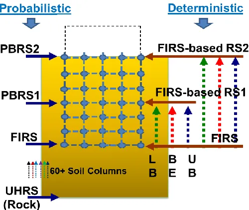
Figure 6 illustrates the process involved in the “extended” NEI check for deep embedment (the term, “extended” NEI Check, is used here as a conceptual extension of the existing evaluation process available for shallow embedment to the case of deep embedment). As in Figure 2 for shallow embedment, the left hand side of Figure 6 illustrates that the FIRS, PBRS1 and PBRS2 are obtained by transferring the UHRS at the base rock to the foundation, to an intermediate depth, and to the surface, respectively, through probabilistic site response analyses involving 60+ randomized soil columns. The performance-based procedure in RG 1.208 is included in this process and the resulting FIRS, PBRS1, and PBRS2 achieve the target performance goal ensuring the performance of the SSCs is acceptable. The PBRS2 established at the surface is also called the PBSRS. Only one additional spectra at an intermediate depth is included in Figure 6 as an illustration; however, PBRS’s at multiple intermediate depths can be considered depending on the complexities of the site subsurface conditions. The FIRS, PBRS1 and PBRS2 are all defined as free-field outcrop spectra. The right hand side of Figure 6 illustrates that the FIRS input motions are transferred through three deterministic soil columns (LB/BE/UB) to determine the free-field motions at interaction nodes used in Equation (1). The free-field motions obtained by transferring the FIRS through the three deterministic soil columns may not necessarily be conservative when compared to their performance-based counterparts based in performance-based, probabilistic site response analyses involving 60+ soil columns. The extended NEI Check is performed to ensure that the deterministic soil columns and associated input
(a)
(b)
motions used in the SSI analysis are adequate and provide conservatism in seismic demand calculations for the safety-related SSCs.
The extended NEI Check for deep embedment involves a multi-step process: (1) develop input motions compatible with the FIRS at the foundation level, (2) transfer the FIRS input motions to the intermediate depths and the surface through three deterministic soil columns (LB/BE/UB), (3) check if the PBRS at a given depth is bounded by the envelope of the three FIRS-based response spectra at the corresponding depth, (4) if all the PBRS’s considered are bounded, the FIRS input motions and the three soil columns can be used for the SSI analysis; if not, add soil columns or modify the FIRS input motion time histories so that all resulting response spectra envelopes bound their corresponding PBRS’s. Guidance on performance check for deterministic SSI soil columns and associated input motions for deeply embedded structures is provided in the DSRS (Ref. 6).
OTHER TECHNICAL CONSIDERATIONS
Although not included in the scope of this paper and not discussed in detail here, there are other technical considerations to be noted with respect to the seismic analysis of deeply embedded SMRs. For instance, the direct method (DM) of substructuring approach may not be feasible for deeply embedded structures due to significant computational demand. In such cases, the subtraction or modified subtraction method (SM or MSM) may be employed and the DSRS (Ref. 6) provides the guidance for evaluating the adequacy of the SM or MSM and allows alternate methods to be used for such evaluation as long as the basis for alternate methods are justified. If incoherence effects to reduce high-frequency motions are included in the SSI response, the DSRS provides guidance that the evaluation needs to include consideration of the potential variation of the coherency function with depth. The PBRS for the vertical direction can be obtained with the appropriate vertical-to-horizontal (V/H) ratios used to develop the vertical FIRS. The DSRS states that the methodology for developing V/H ratios for deep soil site conditions is reviewed on a case-by-case basis. The DSRS also states that proper considerations should be given to other potential technical issues, such as, the extent to which non-vertically propagating shear waves may be more important for deeply embedded structures than for those with shallow embedment depth, the effect of nonlinear behaviour including the soil-structure separation and soil material properties on wall pressure and SSI calculations, the effect of deep embedment on the relative significance of kinematic interaction, and the
impact of deep embedment on the accuracy of sidewall impedance functions calculated with standard methods.
CONCLUSION
Technical issues on the seismic soil-structure interaction analysis of deeply-embedded nuclear power plant structures commonly encountered in SMR designs are addressed and associated technical challenges discussed. Specifically, a process developed for ensuring hazard-consistent seismic input for the site response and SSI analysis for shallow-embedded structures is illustrated using an example from an LWR license application. Then, an extension of the process to deeply-embedded structures captured in the relevant regulatory guidance is discussed and illustrated. Finally, other technical considerations pertaining to the seismic analysis of deeply embedded SMRs are briefly discussed.
DISCLAIMER
Any opinions, findings, and conclusions expressed in this paper are those of the authors and do not necessarily reflect the views of the USNRC.
REFERENCES
[1] Lysmer, J., Tabatabaie-Raissi, M., Tajirian, F., Vahdani, S., and Ostadan, F. (1981): "SASSI - A system for analysis of soil-structure interaction," Report No. UCB/GT/81-02, Geotechnical Engineering, University of California, Berkeley.
[2] DC/COL-ISG-017, Interim Staff Guidance On Ensuring Hazard-Consistent Seismic Input for Site Response and Soil Structure Interaction Analyses, U. S. Nuclear Regulatory Commission, Washington, DC, March, 2010 (ADAMS Accession No. ML100570203).
[3] NEI White Paper, “Consistent Site-Response/Soil-Structure Interaction Analysis and Evaluation,” Nuclear Energy Institute, Washington, DC, June 2009 (ADAMS Accession No. ML091680715).
[4] RG 1.208, Regulatory Guide on A Performance-Based Approach to Define the Site-Specific Earthquake Ground Motion, U. S. Nuclear Regulatory Commission, Washington, DC, March 2007 (ADAMS Accession No. ML070310619).
[5] North Anna Unit 3, Combined License Application, Part 2, Final Safety Analysis Report, Revision 9, June 2016, Chapter 3: Design of Structures, Components, Equipment, and Systems (ADAMS Accession No. ML16218A023).