MCNPX Evaluation of the Integral
Parameters and Power Distribution for PWR
Lattice Benchmark Problem
H. K. Louis and R. M. Refeat
Lecturers, Department of Safety Engineering, Nuclear and Radiological Regulatory Authority (NRRA), Cairo, Egypt
ABSTRACT: Confidence in the neutronic analysis results can be obtained by comparing calculated results with measured data. For this purpose benchmark problems were formulated for various reactor types.In the present paper, infinite multiplication factor, the integral parameters and pin power distribution of a typical PWR assembly are calculated using the current version of MCNPX 2.7 code. The data used are based on experimental PWR benchmark performed by BABCOCK andWILOX, which was formulated by the American Nuclear Society.Also, the effective multiplication factor and the power density distribution are determined for thecores, which include fuel pins, water holes and perturbing (absorbing) pins. The goal of the presentwork is to assess the accuracy of the cross section libraries and the processing methodology that areused. The results show good agreement with those obtained experimentally for core calculations andby other research organizations for assembly calculations.
KEYWORDS: Integral parameters, Power distribution, PWR and MCNPX code.
I. INTRODUCTION
The neutronic analysis of a nuclear reactor includes multiple steps; nuclear data generation, fuel and fuel assembly modeling, lattice parameter generation, and reactor system modeling and analysis. If there is any imperfectness in any of these steps, this will lead to uncertainties in simulation results.It is essential that the computational tools and methods should predict the nuclear reactor system accurately so that the nuclear reactor operates safely and economically as designed, many benchmark problems were formulated to achieve this purpose. One of these benchmarks is based upon light water reactor (LWR) assembly experiments performed by Babcock and Wilcox in the early 1970’s which were formulated as a benchmark[1]. Three assembly configurations are given, first one consists of only fuel pins (assembly type A), the second assembly consists of fuel pins and water holes(assembly type B), the third assembly consists of fuel pins, water holes and perturbing (absorber) pins (assembly type c).These problems are well suited for analysis by assembly codes as well as Monte Carlo codes.
The experiments were performed inside a large aluminum tank containing borated water, UO2 fuel pins, and a number
of perturbing pins. The fuel pins contained low-enriched uranium (LEU) and were clad in aluminum. The water contained soluble boron in the form of dissolved boric acid (H3BO3). The water height was exactly 145 cm. The central
region of the core closely resembled 3x3 array of pressurized water reactor (PWR) fuel assemblies with fuel pins arranged in a 15x15 lattice. The nine assemblies were surrounded by a driver region of LEU fuel pins identical to those in the assemblies. The driver region had an irregular boundary, as shown in figure 1. The region between the driver boundary and the inner wall of the tank contained only water. The vertical dimension of the core is shown in figure2. Many research studies were performed for the specified benchmark using different methodologies with different codes and nuclear data libraries [2]. Some of them use the deterministic method and others use the probabilistic method (Monte Carlo).The methodology of the code that will be used in this paper is the Monte Carlo method so the results will be compared with those using the same methodology. In the following paragraphs some of these studies are mentioned.
Roger N.Blomquist in the Argonne National Laboratory has performed the calculations using VIM code. The libraries used are based on ENDF/B-V, except for the thermal scattering data, which were taken from ENDF/B-III.
Yi-Kang Lee in the CEA (Commissariat à l'énergieatomiqueet aux énergies alternatives) has performed the calculations using TRIPOLI-4 code. The library used is based on JEF2.2.
V.I. Bryzgalov, M.S. Yudkevich in the Russian Research Center, has performed the calculations using MCU-RFFI code. The libraries used are part of the DLC/MCUDAT-1.0 data collection of the MCU project.
In this paper the calculations for a typical PWR assembly in the specified benchmark are performed. The calculations include the infinite multiplication factor, the integral parameters and pin power distribution of the three assembly configurations (A, B, C). The calculations also include the power density distribution at the core mid-plane for the central assembly for cores with assembly types B and C. All the calculations are done using the MCNPX code version (2.7) [3]. The libraries used are the pre ENDF/B-VII evaluation library (T16_2003)[4]for the uranium isotopes and the ENDF66 [5] for the other isotopes. The calculations are also performed using the ENDF71x library[6]. All the results for the assembly calculations are compared with the average of those obtained by the various research organizations that worked on this benchmark using the Monte Carlo techniques, while the results for the core calculations are compared with the available experimental measurements.
Fig.2The Vertical dimensions of the core
II. PWRASSEMBLY DESCRIPTION
The assemblies consist of a 15x15 array of fuel pins, water holes and perturbing pins. All of the loadings are laid out on a square pitch of 1.63576 cm. Assembly type A contains fuel rods in all locations, assembly type B contains 17 water holes, while assembly type C contains 16 Pyrex rods (perturbing pins) inserted in the positions of the water holes except the central hole.
The geometrical characteristics of the Uo2 fuel pins, clad and the perturbing pins are given in table.1 while the materials
compositions are given in table2. Table.3 shows the Boron isotopic concentrations in water , specified for each of the three configurations. The temperature at which the calculations are performed is taken to be 20 ̊C for all the materials.
Table1The geometrical characteristics of the materials
Material PARAMETERS VALUES
Fuel pins
Pellet diameter (cm) 1.029716
Active length (cm) 153.3398
Mass per fuel pin (g) 1305.5
Pellet density (g/cm3) 10.24
Clad (Al-6061)
Outer diameter (cm) 1.205992
Thickness (cm) 0.081280
Length (cm) 156.4386
Density (g/cm3) 2.7
Pyrex Perturbing rods
Diameter (cm) 1.17
Length (cm) 188
Mass(g) 453.6
Table2 The materials compositions
Material Isotope Number Density(a/b-cm)
Fuel pins
U-234 4.5689x10⁻⁶
U-235 5.6868 x10⁻⁴
U-238 2.2268 x10⁻²
O-16 4.5683 x10⁻²
B-10 2.6055 x10⁻⁷
Water H-1 6.6737 x10
-2
O-16 3.3369 x10⁻²
Clad (Al-6061)
Mg (Nat.) 6.2072 x10⁻⁴
Al-27 5.3985x10⁻²
Si(Nat.) 3.2230x10⁻⁴
Ti (Nat.) 4.7263 x10⁻⁵
Cr (Nat.) 5.8029 x10⁻⁵
Mn-55 4.1191x10⁻⁵
Fe (Nat.) 1.8910 x10⁻⁴
Cu (Nat.) 5.9353 x10⁻⁵
Pyrex Perturbing rods
B-10 9.7491 x10⁻⁴
B-11 3.9241 x10⁻³
O-16 4.4829 x10⁻²
Na-23 1.7444 x10⁻³
Al-27 1.0018 x10⁻³
Table3. Boron Isotopic Concentrations in Water
Configuration Critical Soluble Boron Concentration(PPM)
Number Density (a/b-cm)
B-10 B-11
A 1511 1.6769 x10⁻⁵ 6.7497 x10⁻⁵
B 1335.5 1.4821 x10⁻⁵ 5.9657x10⁻⁵
C 794 8.8117 x10⁻⁶ 3.5468x10⁻⁵
III. LIBRARIES AND CODE USED
MCNPX is a general-purpose Monte Carlo N–Particle code that can be used for neutron, photon, electron, or coupled neutron/photon/electron transport, including the capability to calculate eigenvalues for critical systems. The code treats an arbitrary three-dimensional configuration of materials in geometric cells bounded by first- and second-degree surfaces and fourth-degree elliptical tori. Pointwise cross-section data are used.
In this paper the MCNPX code [3]is used to simulate the assembly for the three configurations (A, B, C), with two sets of cross section libraries. In the first set (Set I) the cross section data for the uranium isotopes are taken from the pre ENDF/B-VII evaluation library (T16_2003), while the cross section data for the other isotopes are taken from the ENDF/B-VI (ENDF66). Thermal neutrons are described by both the free gas and S (α, β) models.
The continuous-energy MCNP neutron library T16_2003 has been created for 15 isotopes, the library is based upon recent Los Alamos GroupT-16 evaluations. Data are provided for 3H, 232U, 233U, 234U, 235U, 236U, 237U,238U, 239U, 240U,
241U, 237Np, 239Pu, 241Am, and 243Am.The majority of the evaluations represented on T16_2003 are intended to be tested
as candidates for ENDF/B-VII[4].
The ENDF66 library contains data for 173nuclides based on ENDF/B-VI evaluations of the cross Section Evaluation Working Group (CSEWG) and was processed with the NJOY99 code. Updated evaluations for uranium, plutonium, tungsten, and iron isotopes have been performed[5].
In the second set (Set II) the cross section data for all of the isotopes are taken from the ENDF71x library and the thermal neutrons are described by both the free gas and S (α, β) models.The ENDF71x libraryis a thoroughly tested set of ACE-format data tables released by the Nuclear Data Team at Los Alamos National Laboratory (LANL). It is based on ENDF/B-VII. 1, the most recently released set of evaluated nuclear data files produced by the US Cross Section Evaluation Working Group (CSEWG).A variety of techniques were used to test and verify the ENDF71x library before its public release.A comparison of ENDF71x with its predecessor ACE library, ENDF70, showed that dramatic changes have been made in the neutron cross section data for a number of isotopes between ENDF/B-VII.0 and ENDF/B-VII.1. Based on the results of the verification tests and the validation tests performed by Kahler, et al., the ENDF71x library is recommended for use in all Monte Carlo applications[6].
IV. INTEGRAL PARAMETERS
The integral parameters are a number of quantities which are useful in a comparison of different analysis techniques and basic data. Therefore, the following quantities for an infinite lattice should be computed[1]:
- Infinite multiplication factor (K∞)
- δ25 , that is the ratio of epithermal-to-thermal 235U fissions - δ28, that is the ratio of 238U fissions to 235U fissions
V. CALCULATION RESULTS AND DISCUSSION
1- Lattice calculation results
Tables4, 5, 6 and 7 show the values of infinite multiplication factors and integral parameters for assembly types A, B and C respectively. The calculations are performed using MCNPX (2.7) code and the nuclear data libraries Set I and Set II.The results are compared with the averaged from Monte Carlo results that are mentioned in reference 7.
Table4Comparison of the infinite multiplication factors
Avg. MC Set II Set I Assembly type 1.05607 1.06059 1.05692 A 1.04697 1.05131 1.04782 B 0.98558 0.98888 0.98662 C
Table5 Results of integral parameters for assembly type A
Avg. MC SetII SetI Parameters 0.1301 0.1446 0.145 δ25 0.06478 0.0635 0.0642 δ28 0.34234 0.3714 0.3718 ρ25 2.26459 2.304 2.2879 ρ28 0.46676 0.4608 0.464 CR
Table6 Results of integral parameters for assembly type B
Avg. MC SetII SetI Parameters 0.11534 0.1285 0.1290 δ25 0.06011 0.0589 0.0596 δ28 0.30377 0.3301 0.3302 ρ25 2.0210 2.049 2.0352 ρ28 0.43701 0.432 0.4353 CR
Table7 Results of integral parameters for assembly type C
Avg. MC Set II Set I Parameters 0.12862 0.1424 0.1428 δ25 0.06592 0.06448 0.0651 δ28 0.33900 0.367 0.375 ρ25 2.25849 2.289 2.273 ρ28 0.46451 0.459 0.463 CR
Fig.4 Pin power distribution for assembly type B
Fig.6Pin power distribution for assembly type C
Fig.7Errors of Pin power distribution for assembly type C
It is shown from the above tables and figures that the results obtained for assembly types A, B and C are in good agreement with the Average Monte Carlo results mentioned in reference 7.
2- Core calculation results:
Table 8 shows the values of effective multiplication factors obtained using MCNPX (2.7) code and the nuclear data libraries Set Iand Set IIfor core configurationswith assembly type A, B and C. The results are compared withboth the experimental values and the average calculations with Monte Carlo.
Table8 Comparison of the effective multiplication factors
Exp. Avg. MC
Set II Set I
Core type
1.0007 0.99754
0.99932 0.99631
A
1.0007 0.99729
0.99994 0.99645
B
1.0007 0.99611
0.99920 0.99603
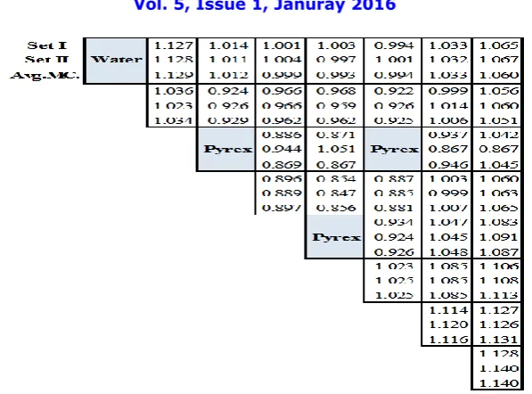
Figures8 and 10 show the results of the pin power distribution at the core mid-plane for the central assembly of core configurations with assembly types B and C respectively. The results obtained using the nuclear data libraries Set I and Set II are compared with the experimental results. The errors for the results of the nuclear data libraries Set I and Set II with respect to the experimental results are shown in Figures 9 and 11.
Fig.8Core power distribution for assembly type B
Fig.10Core power distribution for assembly type C
Fig.11Errors of core power distribution for assembly type C
It is shown from the above tables and figures that the results obtained for core configurations with assembly types A, B and C are in good agreement with the experimental results mentioned in reference 7.
VI. CONCLUSION
ACKNOWLEDGMENT
The Authors would like to express their deep appreciation and thanks to Prof. Dr. E. H. Amin (Safety Engineering Department, ENRRA, Cairo, Egypt) for her valuable scientific guidance, support and encouragement during this work.
REFERENCES
[1] PWR lattice benchmark problems, Ad Hoc committee on reactor physics benchmarks, American Nuclear Society, April 1996.
[2] mcd.ans.org/jb/bench/PWRLattice/Contributions
[3] MCNPX User's Manual. Version 2.7.0, Los Alamos National Laboratory, LA-CP-11-00438, 2011.
[4] Robert C. Little: MCNP Neutron Library T16_2003, LANL memorandum LA-UR-04-4520, Los Alamos National Laboratory, Los Alamos, NM, 2004.
[5] J. M. CAMPBELL, S. C. FRANKLE, and R. C. LITTLE, “ENDF66: A Continuous-Energy Neutron Data Library for MCNP4C,” Los Alamos National Laboratory report
LA-UR-02-3000 (2002).
[6] M.B. Chadwick, et.al, ENDF/B-VII.1 Nuclear Data for Science and Technology: Cross Sections, Covariance, Fission Product Yields and Decay Data, 2011.