ISSN: 2319-8753
International Journal of Innovative Research in Science,
Engineering and Technology
(An ISO 3297: 2007 Certified Organization)
Vol. 2, Issue 12, December 2013
Copyright to IJIRSET www.ijirset.com 7369
Addressing Problems by Systems Engineering
Methods, Techniques, and Tools-Model
Framework
Nihal M.A. El-Sayar
*1, Islam Helaly Abdel-Aziz Afefy
2, A. M. El-kamash
3P.G. Student, Industrial Engineering Dept, Engineering Faculty, Fayoum University, Fayoum, Egypt 1 Assistant professor, Industrial Engineering Dept, Engineering Faculty, Fayoum University, Fayoum, Egypt 2
Professor, Industrial Engineering Dept, Engineering Faculty, Fayoum University, Fayoum, Egypt3
Abstract: Systems Engineering is an interdisciplinary and holistic discipline with methods and techniques to address
complex problems. This paper proposes an integration of system life-cycle processes and stages from ISO/IEC 15288 with the proposed tools-model framework as a basic framework, allowing team to generate data, define customer needs, optimize solutions, architecture the system, make decisions, validate, analyze failures, and realize the system. This paper gives a short presentation of tools-model framework application on a real case in industry. The application of this proposed model led to a significant increase of the firm total and (labors, materials) partial productivity, quality-productivity index, profit, and value added almost by (39%, 65%, 20%, 39%, 202%, and 119%) respectively, noticeable positive decrease of defective products percentage, downtime, rework, and lead time almost by (79%, 28%, 98%, and 80%) respectively, also acquiring new customers and new products, besides developing training programs, and solving customer claims.
Keywords: Systems Engineering (SE), ISO/IEC 15288, systems engineering tools, Systems life-cycle integration,
Systems Engineering Lifecycle-Tools-Model Framework (SELTMF)
INTRODUCTION
ISSN: 2319-8753
International Journal of Innovative Research in Science,
Engineering and Technology
(An ISO 3297: 2007 Certified Organization)
Vol. 2, Issue 12, December 2013
Copyright to IJIRSET www.ijirset.com 7370
challenges, such as energy problem through defining problem by articulating the problem in its context as clearly as possible, Sharpening the problem further by transforming it into need statements and using SE modeling and analysis techniques to understand, communicate, debate, and facilitate decisions about complex problems and assessing potential solutions. Albert and John [9] described a novel approach through development of V-model for integrating manufacturing and supply chain considerations into the SE process applied for aerospace and defense industry through the cost of developing new generation of system continues to spiral out of control. Marianne and Gerrit [10] investigated the value of specific SE tools applied to the flow and storage of finished products included: context diagram, physical architecture, Integration Definition for Function Modeling (IDEF0) diagrams, Use Case Scenarios, Scenario Tracing and Geographical Model. As risk analysis and affordability, Quentin [11] used affordability as a decision making tool, which can be approved, measured and predicted. he provided analytical path from determining requirements to fielding affordable systems conducting research into the concepts of affordability and methods to implement the approach. He also established a foundation for creating affordability SE Sciences, he initiated research of complexity sciences to understand links between fitness and affordability, and also investigated game theoretical modeling and other advanced SE concepts to focus on thrusts. Hee et. al [12] used the SE approach to guide the development of a new business model-based design method using these tools though the project phases such as IDEF0 model, functional architecture, Strength, Weakness, Opportunity, Threats (SWOT) analysis, buyer utility map, fault analysis tree, pre-defined assessment system, Quality Function Deployment (QFD), and system analysis and control including trade-off studies, effectiveness analyses, risk management, configuration management, interface management, data management, and so on. By using SE, project success rates were enhanced from 16% to 28% in 2000. The design process for damage control support systems was based on SE process of ISO/IEC 15288, EIA/ANSI 632, and IEEE 1220. The International Standard, Systems Engineering Life Cycle Processes, (ISO/IEC 15288) [13] established a common framework for describing the life cycle of systems and defined a set of processes and stages. These processes can be applied at any level in the hierarchy of a system’s structure to the whole life-cycle including conception, development, production, utilization, support and retirement of systems using tasks of defining customer needs, stating the system problems, investigating solutions, modeling the system of interest, managing functions interfaces, and assessment of the system to get a product or introduce a service. The life-cycle processes can be applied concurrently and iteratively to a system and its elements on any system. It therefore applies to one-of-a-kind, mass-produced, customized and adaptable systems or services systems. Department of Defence (DoD), NATO, Ministry of Defence (MoD), and National Aeronautics and Space Administration (NASA) all developed SE model frameworks and NATO has decided that ISO/IEC 15288 shall be the framework for Systems Life-Cycle Management (SLCM) [14]. NASA [15] has provided its own SE framework to be a general guidance and information on SE that will be useful to the NASA community. Tommy et. al [14] presented an example on how ISO/IEC 15288, Architectural Frameworks and Modeling and Simulation (M&S) can be integrated and the benefits of that integration, especially how M&S can be used to develop and execute system designs giving a presentation of some ideas concerning tool support such as MODAF with six viewpoints. The existing frameworks depended on one or more SE tools, however system life-cycle processes, stages can be integrated using a complete SE tools-model framework. So, the present paper introduces to ISO/IEC 15288 life-cycle processes and stages, aiming to present the proposed model framework of system life-cycle integration using support tools as the basic building blocks in this model. It presents how the life-cycle processes, stages, and tools can be integrated and the benefits of that integration, especially how SE tools can be used to present, model, develop and execute the system. It also assess this proposed model by applying it to a real industrial case to improve its system performance.
SYSTEMS ENGINEERING LIFE-CYCLE The System Life-cycle Processes
ISSN: 2319-8753
International Journal of Innovative Research in Science,
Engineering and Technology
(An ISO 3297: 2007 Certified Organization)
Vol. 2, Issue 12, December 2013
Copyright to IJIRSET www.ijirset.com 7371
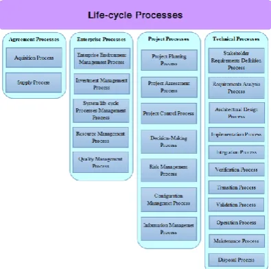
Fig. 1. Systems engineering life-cycle processes - ISO/IEC 15288
The System Life-Cycle Stages
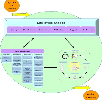
The life cycle stages/phases - according to ISO/IEC 15288 - provide a framework for the detailed modeling of system life cycles using the system life cycle processes described above to model life cycles of the systems. Every system of interest (SOI) has its own life-cycle, that can be decomposed into a set of stages. An example of a life-cycle six stages [13], is shown in Figure 2.
Fig. 2. Life-cycle six stages - ISO/IEC 15288
The life cycle is partitioned into a system life-cycle period of time where each one period is represented by each stage and has a distinct purpose. The partitioning is practical since it is easier to work in small, understandable and timely steps.
ISO/IEC 15288 LIFE-CYCLE PROCESSES, PHASES, AND SE TOOLS INTEGRATION
ISSN: 2319-8753
International Journal of Innovative Research in Science,
Engineering and Technology
(An ISO 3297: 2007 Certified Organization)
Vol. 2, Issue 12, December 2013
Copyright to IJIRSET www.ijirset.com 7372
Fig. 3. An example matrix of life-cycle processes, stages, and proposed tools categories in relation matrix
A.The Systems Engineering Lifecycle-Tools-Model Framework
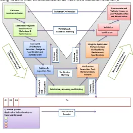
The system frameworks make it possible to describe and communicate systems within and between organizations, providing that, the same, or similar frameworks are used. Without a common language it is difficult to communicate. Systems Engineering Life-cycle Tools-Model Framework (SELTMF), provide guidelines regarding content and how to describe, solve, and present systems different issues into full system framework over its life-cycle; besides they provide guidance concerning how to design or implement a specific system or element, or how to develop or acquire systems not only using traditional steps but through architecture tooling framework. The proposed SELTMF is illustrated by Figure 4. SE tooling is used to identify capability needs, relate needs to systems development and integration, attain information interoperability and supportability, and therefore manage investments.
Fig. 4. System interaction with typical life-cycle processes and stages and SE tools as the basic building blocks
THE SYSTEMS ENGINEERING TOOLS
ISSN: 2319-8753
International Journal of Innovative Research in Science,
Engineering and Technology
(An ISO 3297: 2007 Certified Organization)
Vol. 2, Issue 12, December 2013
Copyright to IJIRSET www.ijirset.com 7373
mathematical, graphical, modeling, and architecture [16, 17, 18]. SE Tools demonstrate how using integrated or concurrent engineering methods, copiously illustrated with figures, charts, and graphs offering methods, frameworks, and techniques for designing, implementing, and managing systems exhibiting the effect of the SE concept and its importance during the design and development of a complex system.
A. The Systems Engineering Tools Framework
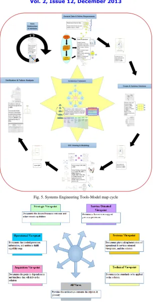
The efforts within the area of frameworks that we know of; the Incremental Commitment Spiral Model, Model Oriented Systems Engineering, Model Driven Architectures, Model-Based Systems Engineering, Department of Defense Architectural Framework, and Ministry of Defense Architectural Framework (ICSM, MOSES, MDA, MBSE, DoDAF, and MoDAF) all strives to create a common architecture framework for descriptions of system architectures [19, 20, 21, 22, 14, 23]. According to interpretations, the main goal with any model framework, is to support development and documentation, of the system, defining stakeholders and communicating between them. Systems frameworks may use one or more tool to demonstrate the system of interest. ―Systems Engineering Tools Framework - SETF‖ map presents the tools application through the whole life-cycle of any system, the proposed tools for each level, and the application cycle over the life-cycle, that is illustrated by Figure 5. The tools are categorized into four main groups illustrating its utility and usage through the proposed SE model, these categories and tools utilization into the SE model are as follow:
Architecture framework; is considered a general step in the tools-model framework and is the core of this framework. It is a way to viewing and defining an enterprise, providing a comprehensive approach for designing, planning, implementing, and governing an architecture.
Defining requirements; gathering, defining, and analyzing data of customer or system requirements, where tools such as Affinity Diagram, Need Means Analysis, Viewpoint Analysis can be used during the system concept stage to state the system issues.
Creating and optimizing solutions; investigating, exploring, and assessing existing development system and proposed solution alternatives using Function Means Analysis for example, and FFMEA to determine and prioritize failure modes.
System viewing and modeling; to determine system reliability, presenting, and assessing system development and utilization it is needed to view this system using modeling tools such as V-model or IDEF.
System verification and analysis; system supportability, testing, assessment, or failure analysis can be done using Quality Function Deployment or Fault tree Analysis and then get system feedback to reevaluate its solution concepts.
The Systems Engineering Tools Framework Application Examples
There are an increasing number of opportunities for systems engineers to make important contributions for manufacturing and services fields. The filed of application is a company, which is considered a subcontractor (tier) serving many companies in Egypt working in many fields such as vehicles (the biggest customer), plastics, electrical equipments, etc. This industry undergo some main stages in the manufacturing process as design, receiving raw materials, sheet metal cutting and pressing, plastic injection, assembly, treatment and painting, and finally delivering to customer. The SE is applied to this company considering it all as a system using SETF categories to present this system treating its issues.
ISSN: 2319-8753
International Journal of Innovative Research in Science,
Engineering and Technology
(An ISO 3297: 2007 Certified Organization)
Vol. 2, Issue 12, December 2013
Copyright to IJIRSET www.ijirset.com 7374
Fig. 5. Systems Engineering Tools-Model map cycle
ISSN: 2319-8753
International Journal of Innovative Research in Science,
Engineering and Technology
(An ISO 3297: 2007 Certified Organization)
Vol. 2, Issue 12, December 2013
Copyright to IJIRSET www.ijirset.com 7375
2)Defining Requirements: To describe these tools clearly, they are applied to a real system that is an industrial firm is considered as a second tier to vehicles assembly firms and this is one of the company’s varied activities. This plant is needed to fulfill customer requirements, so it has its entire requirements and validation system to ensure its ability to compete and test solutions of improvement. Teamwork is configured to discover the considered requirements, Viewpoint Analysis (VPA) is a tool of requirements gathering and data analysis tools, which has been applied to identify requirements, as illustrated by Figure 7. The main boxes present the functional requirements, while the surrounded ones are non-functional requirements (constraints).
Fig. 7. VPA - the final viewpoint structure chart for ICDI firm
3)
Optimizing Proposed Alternatives: The teamwork is considered to explore and assess the proposed alternative solutions not to be a temporary solution for present but to be comprehensive for all levels, so Need Means Analysis (NMA) - the box of nine - is a proper alternatives investigating tool for this issue, as illustrated by Figure 8. This example presents treatment and painting department issues that result in non-qualified painted parts of treating and painting processes. The central box contains the current SOI; the treatment basins and painting unit. Its operational requirement (OR) is to treat and paint finished parts. There are three system levels the higher level considering new systems thinking, the same system level is to improve the current SOI with a new architecture, and the lower level treats new subsystems.
ISSN: 2319-8753
International Journal of Innovative Research in Science,
Engineering and Technology
(An ISO 3297: 2007 Certified Organization)
Vol. 2, Issue 12, December 2013
Copyright to IJIRSET www.ijirset.com 7376
4)SOI Modeling: To present the system and state the issues for any system of interest, firstly the actual system process life-cycle has to be understood and then identifying points of weakness through this life-cycle by modeling the system life-cycle using V-model as a system development tool as illustrated by Figure 9. This model presents the firm processes life-cycle starting at defining customer needs until delivering orders, it is obviously noticed that the main points of lack lie on:
Receiving of raw and consumable materials,
Products quality,
Order delivery time (delay time), and
Management (organizing orders and communications between administrations).
Fig. 9. V - model of system engineering processes for ICDI firm
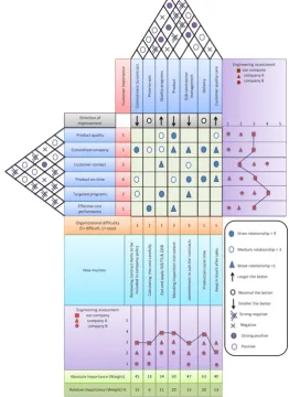
5)System Verification and Failure Analysis: It is required for any system to verify and assess its performance, cost, and risk to ensure it is on track for fulfilling customer needs, also to verify and continuously assess system performance that is useful for feedback and re-evaluating the system. Quality Function Deployment (QFD) is a tool for detecting system development and relationships among main functions, as illustrated by Figure 10. The QFD, - as known - its left side presents the voice of the customer, the roof presents the voice of the company itself, and the lower part presents how the company shall fulfill customer requirements. The parts of comparing the current company to other customer’s tiers and to measure the company gap to targets its weight is calculated by; [ Ʃ (Priority x Relationship)], where the priority is the customer importance and the relationships presents the value assessment matrix between the voice of the customer and the voice of the company.
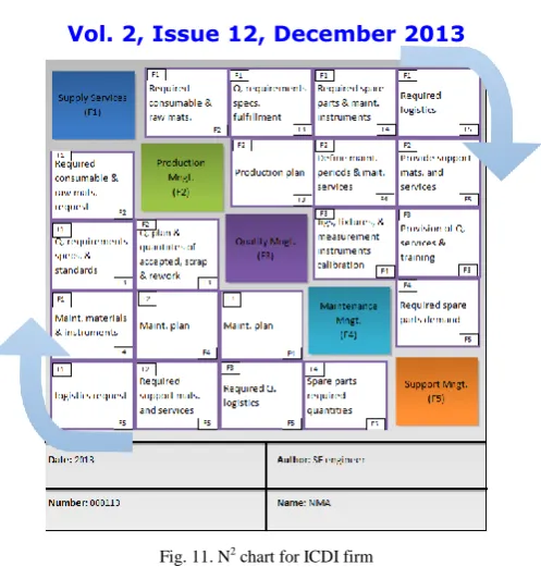
6)System Integration: Integration means designing interfaces and bringing system elements together so they work as a whole. This requires extensive communication and coordination. Interfaces between different subsystems, the main system and the customers must be designed. Subsystems should be defined to minimize the amount of information to be exchanged between the subsystems. Figure 11 illustrates the use of an interfaces tools that is N2 chart. This N2 diagram represents and analyses the functional or physical interfaces between system elements. As shown by Figure 10, the central main blocks presents functions (system elements) numbered by F(n) according to the function number, the upper side of this matrix presents the forward relationship from function to another, and the lower side of the matrix presents the backword relationship.
ISSN: 2319-8753
International Journal of Innovative Research in Science,
Engineering and Technology
(An ISO 3297: 2007 Certified Organization)
Vol. 2, Issue 12, December 2013
Copyright to IJIRSET www.ijirset.com 7377
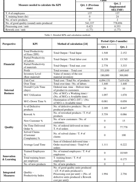
During the operating of the SELTMF on the system life cycle the performance of the system should be developed. Initially the following measurements will be done to validate that the system is in compliance with its requirements. The system is assessed by using some performance measures, some enterprise Key Performance Indicators - KPIs for the whole investment [24], are used to assess the system an compare the situation before applying the SELTMF and during applying it. These measures are applied to the application firm during two periods one before applying the SELTMF and the other one is during the application of this proposed model as an assessment method. Each period is three months means a quarter of the year (Qrt). The suggested KPIs are illustrated by; Table 1 that represents the needed measures for these KPIs, and detailed analysis of these KPIs and how to be calculated are illustrated by Table 2.
ISSN: 2319-8753
International Journal of Innovative Research in Science,
Engineering and Technology
(An ISO 3297: 2007 Certified Organization)
Vol. 2, Issue 12, December 2013
Copyright to IJIRSET www.ijirset.com 7378
Fig. 11. N2 chart for ICDI firm
Table 1. Needed measures data for the KPIs from ICDI firm through two quarters
Measure needed to calculate the KPI
Value
Qrt. 1 (Previous state)
Qrt. 2 (Implemented
SELTMF)
Total (T.) Firm Revenue (Output) (L.E) 1,500,000 3,000,000
T. Firm Costs (Input) (L.E) 968,970 1,394,355
T. Labor Costs (L.E) 179,904 217,950
Material cost (L.E) 540,000 900,000
Raw material Inventory money value (L.E) 180,000 300,000
Total number (T. #) of products (unit) 159 183
T. Over time (L.E) 145.46 145.46
Number (No.) of labors 101 101
Ordered material time (day) 20 (-10) 10
Deliver time of products to customers (day) 29 20
No. of M/Cs (unit) 54 54
Working time (hr) 544 736
Available time (hr) 496 688
M
/
C
sdown time (day) 2.72 2.72
T. quantity of used material (ton) 150 150
No. of defective products (unit) 12,871 3,497
T. # of produced products (unit) 588,078 783,024
No. of reworked products 33,870 671
No. of new customers 0 3
No. of customers 17 20
No. of orders delivered on time 0 7
T. # of orders 9 9
No. of solved claims 0 3
T. # of claims 3 3
Order delivered time (day) 20 20
Order received time (day) 30 22
ISSN: 2319-8753
International Journal of Innovative Research in Science,
Engineering and Technology
(An ISO 3297: 2007 Certified Organization)
Vol. 2, Issue 12, December 2013
Copyright to IJIRSET www.ijirset.com 7379
Measure needed to calculate the KPI
Value
Qrt. 1 (Previous state)
Qrt. 2 (Implemented
SELTMF)
T. # of employees 137 137
T. training hours (hr) 0 24
No. of new products 0 2
No. of good quality (sound) units produced 541,337 778,856
Processing cost / unit 0.423 0.353
Rework cost / unit (1.77) (1.77)
Table 2. Detailed KPIs and calculation methods
Perspective KPI Method of calculation [24]
Period (Qrt=3 months)
Qrt. 1 Qrt. 2
Financial
Total Productivity
of Firm (TPF) Total Output / Total Input 1.548 2.152
Partial Productivity
of Labors Total Output / Total labor cost 8.338 13.765
Partial Productivity
of materials Total Output / Total mat. cost 2.778 3.333
Profit Total revenue – Total cost 531,030 1,605,645
Inventory Level (Raw material)
Value of money of the raw
material inventory 180,000 300,000
Internal Business
Unit Cost Total cost / Total No. of products 6,094.151 7,619.426
Over Time Total over time / No. of labors 1.440 1.440
Overall Cycle Time (days)
Ordered mat. time – Deliver time
of product to customers 39 10
M/C Utilization (No. of M/Cs x Working time) /
(No. of M/Cs x Available time) 1.097 1.070
M/Cs Down Time % (Summation of M/Cs DT ) / (No.
of M/Cs x Available time) 0.081 0.058
Quality
% of Defective products
No. of defective products / No. of
produced products 2.189 0.447
Rework % No. of reworked products / T. # of
products 5.759 0.086
New Customer % No. of new customers / No. of
customers 0 15
On-Time Delivered Order %
No. of ordered delivered on time /
T. # of orders 0 77.778
Solved Claims (Customer Complaints) %
No. of solved claims / T. # of
claims 0 100
Average Lead Time
Sum of (Ordered delivered time – Order received time) / Total # of orders
1.111 0.222
Innovation & Learning
Trained Employees %
No. of trained employees / T. # of
employees 0 10.949
Total training hours per employee
T. training hours / T. # of
employees 0 0.175
No. of new products No. of new products 0 2
Integrated Measures
Quality – Productivity Index
No. of good quality units produced / ([T. # of units produced x Processing cost per unit] + [No. of defective units produced x Rework cost per unit])
ISSN: 2319-8753
International Journal of Innovative Research in Science,
Engineering and Technology
(An ISO 3297: 2007 Certified Organization)
Vol. 2, Issue 12, December 2013
Copyright to IJIRSET www.ijirset.com 7380
Perspective KPI Method of calculation [24]
Period (Qrt=3 months)
Qrt. 1 Qrt. 2
Value Added Revenue – Mat. Cost 960,000 2,100,000
Value Added % Value Added / Mat. Cost 177.778 233.333
The analysis of the company performance ensures that due to SE application the company started to improve its performance as illustrated by measures. This is noticed through: a significant increase of the firm total and (labors, materials) partial productivity, quality-productivity index, profit, and value added almost by (28%, 39%, 17%, 28%, 67%, and 54%) respectively, noticeable positive decrease of defective products percentage, rework, and lead time almost by (+100%, +100%, and +100%) respectively, also acquiring new customers and new products, besides developing training programs, and solving customer claims.
CONCLUSION
While there are challenges implementing any approach, it is possible to get some helpful information and recommended reforms. Many organizations divide their Systems into three main categories according to their major workflows that is recommended to be done into this company of application: Requirements definition, Architectural design and Testing and verification. This firm as like many companies its priorities are based on cost and revenue, that is not a flaw but it does not realize that in order to get high marks for low cost it should be interested in three major pillars: Human factor, Administration hierarchy organizing, and Quality issues. This enterprise system should set up a configuration (modification) management and project management All of these SE activities must be documented in a common repository, it could be hardware or software.
REFERENCES
1) A. Terry Bahill and Frank F. Dean: "What Is Systems Engineering? A Consensus of Senior Systems Engineers", 1994 to 2009 by Terry Bahill and Frank Dean, (Last changed January 15, 2009).
2) Frank R. Parth: "Systems Engineering Drivers in Defense and in Commercial Practice", John Wiley & Sons, Inc. Correspondence, (1998). 3) Clement Smartt and Susan Ferreira, "Advancing Systems Engineering in Support of the Bid and Proposal Process", Wiley Periodicals, Inc.,
Regular Paper, (2010).
4) Russell Lock, "Developing a Methodology To Support the Evolution of System of Systems Using Risk Analysis", Systems Engineering Vol. 15, No. 1, 2012, Wiley Periodicals, Inc., Regular Paper, (2011).
5) I. D. L. Bogle, A. R. Cockshott, M. Bulmer, N. Thornhill, M. Gregory, and M. Dehghan: "A Process Systems Engineering View Of Biochemical Process Operations", Elsevier Science Ltd, (1996).
6) Mark Schaeffer, "Software Engineering and Systems Engineering in the Department of Defense", (October 1998).
7) David M. Curry, "Practical application of chaos theory to systems engineering" , New Challenges in Systems Engineering and Architecting Conference on Systems Engineering Research (CSER) 2012–St. Louis, MO Cihan H. Dagli, Editor in Chief Organized by Missouri University of Science and Technology, Elsevier Ltd. Selection, (2012).
8) Jamal Safi, Gerrit Muller, and Maarten Bonnema, "Applying Systems Engineering on Energy Challenges ", New Challenges in Systems Engineering and Architecting Conference on Systems Engineering Research (CSER) 2012 – St. Louis, MO Cihan H. Dagli, Editor in Chief Organized by Missouri University of Science and Technology, Elsevier Ltd. Selection, (2012).
9) Albert Sanders, and John Klein: "Systems Engineering Framework for Integrated Product and Industrial Design Including Trade Study Optimization", New Challenges in Systems Engineering and Architecting Conference on Systems Engineering Research (CSER) 2012 – St. Louis, MO Cihan H. Dagli, Editor in Chief Organized by Missouri University of Science and Technology, Elsevier Ltd. Selection, (2012). 10) Marianne I. Drotninghaug, and Gerrit Muller: "The Value of Systems Engineering Tools for Understanding and Optimizing the Flow and
Storage of Finished Products in a Manganese Production Facility", (2009).
11) Quentin Redman, "Why Affordability is a Systems Engineering Metric", New Challenges in Systems Engineering and Architecting Conference on Systems Engineering Research (CSER) 2012 – St. Louis, MO Cihan H. Dagli, Editor in Chief Organized by Missouri University of Science and Technology, Elsevier Ltd. Selection, (2012).
12) Hee Jin Kang, Jong-Gye Shin, and Jong Kap Lee, "A Business Model-Based Design of a Damage Control Support System for Naval Ships", Systems Engineering Vol. 15, No. 1, 2012, Wiley Periodicals, Inc., Regular Paper, (2011).
13) International Standard, "Systems engineering — System life cycle processes, Ingénierie systèmes — Processus de cycle de vie des systèmes", ISO/IEC 15288:2002, Reference number ISO/IEC 15288:2002(E), (First edition 2002-11-01).
14) Dr. Tommy Nordqvist, Ms. Anna Edberg, Mr. Håkan Byström, and Mrs. Marie-Louise Gustafsson "Systems Engineering, Architecture Frameworks and Modelling & Simulation".
15) National Aeronautics and Space Administration ―Systems Engineering Handbook‖, NASA Headquarters, NASA/SP-2007-6105 Rev1, Washington, D.C. 20546, (December 2007).
16) Dr Stuart Burge, ―The Burge Hughes Walsh Tool Box‖, Version 1.2, Burge Hughes Walsh (2004 - 2011). 17) http://en.wikipedia.org/wiki/Main_Page (Systems Engineering Tools).
ISSN: 2319-8753
International Journal of Innovative Research in Science,
Engineering and Technology
(An ISO 3297: 2007 Certified Organization)
Vol. 2, Issue 12, December 2013
Copyright to IJIRSET www.ijirset.com 7381
(DC): National Academies Press (US); (2005).
19) Joanna F. DeFranco, Colin J. Neill, and Roy B. Clariana: "A Cognitive Collaborative Model To Improve Performance in Engineering Teams—A Study of Team Outcomes and Mental Model Sharing", Wiley Periodicals, Inc., Regular Paper, (2010).
20) Ricardo Pineda, Amit Lopes, Bill Tseng, and Oscar H. Salcedo: "Service Systems Engineering: Emerging Skills and Tools", New Challenges in Systems Engineering and Architecting Conference on Systems Engineering Research (CSER) 2012 – St. Louis, MO Cihan H. Dagli, Editor in Chief Organized by Missouri University of Science and Technology, Elsevier Ltd. Selection, (2012).
21) Florian Schneider, Helmut Naughton, and Brian Berenbach, "A modeling language to support early life-cycle requirements modeling for systems engineering", New Challenges in Systems Engineering and Architecting Conference on Systems Engineering Research (CSER) 2012– St. Louis, MO Cihan H. Dagli, Editor in Chief Organized by Missouri University of Science and Technology, Elsevier Ltd.Selection, (2012). 22) Ali Mostashari, Sara A. McComb, Deanna M. Kennedy, Robert Cloutier, and Peter Korfiatis: "Developing a Stakeholder-Assisted Agile
CONOPS Development Process", Systems Engineering Vol. 15, No. 1, 2012, Wiley Periodicals, Inc., Regular Paper, (2011).
23) Chris Piaszczyk, "Model Based Systems Engineering with Department of Defense Architectural Framework", Systems Engineering Vol 14, No. 3, 2011, Wiley Periodicals, Inc., Regular Paper, (2011).