THIS MANUAL The Installation Service Manual provides the information required to install, program, and maintain the Electra Professional IZO/Level II/Level II Advanced systems.
This manual contains the following chapters : Chapter 1: Introduction
Chapter.1 provides a top-level description of the Electra Professional lZO/Level D/Level II Advanced systems and includes applicable FCC requirements and UL regulatory information.
Chapter 2: Electra Professional 120 Hardware Specifications and Installation Chapter 2 provides the information required to prepare and install the Electra Professional 120
Chapter 3: Electra Professional Level II/Level II Advanced Hardware
Specfications
and InstallationChapter 3 provides the information required to prepare and install the Electra Professional Level II and Level II Advanced systems.
Chapter 4: Termiual Installation
Chapter 4 provides information needed to install applicable terminals. Chapter 5: Programming
Chapter 5 provides detailed instructions for performing System Programming. Chapter 6: Guide to Feature Programming
Chapter 6 provides a roadmap of the Memory Blocks associated with a feature that are either required or can be programmed.
Chapter 7: System Maintenance
Chapter 7 provides maintenance instructions and flowcharts for the systems. Chapter 8: Dtem Cordless Terminal
Chapter 8 provides operating instructions for the Dkrm Cordless Terminal.
SUPPORTING
DOCUMENTS In addition to the Installation Service Manual, the Electra Professional 12OILevel II/Level II Advanced systems are supported by the following technical manuals:
Electra Professional 12O/Level IIkevel II Advanced General Description Manual (Stock Number 722085)
Electra
Professional
12O/Level II/Level
II
Advanced
Features
and
Specifications Manual (Stock Number 722086)
Provides an expanded discussion of each available feature for the Electra Professional l%O/Level II/Level II Advanced systems. In addition, the Features and Specifications Manual provides Station Application, Operating Procedures, and Service Conditions.
Electra Professional lZO/Level II/Level II Advanced Station Operations Manual
(Stock Number 722088)
This manual explains in detail the station operations for all station user features and is for use by installers and end users.
Electra Professional 12O/Level II/Level II Advanced Job Specifications Manual
(Stock Number 722089)
Used in conjunction with the Installation Service Manual, this manual is for the service technicians who are responsible for planning the system installation, maintaining the System, and keeping
records
of system progr anuning and configuration. [This manual is included with the CPU-F( l-20 KTU.1Electra
Professional
12O/Level II/Level
II
Advanced
Automatic
Call
Distribution Manual (Stock Number 720236)
This manual is also included with the MIF-F(A)-10 KTU ( Stock Number 7202331, and provides the service technician with the instructions for programming the ACD feature. This manual is also for the ACD supervisor, at the customer site, to use to become familiar with the system and take full advantage of the ACD/MIS feature.
Electra Professional 12O/Level II/Level II Advanced Least Cost Routing Manual
This manual is included with the Least Cost Routing software (Stock No. 722309). It provides instructions for the service technician for programming the customer site for Least cost Rmlting.Electra
Professional
12OILevel II/Level
II Advanced
System Program
Technician Manual
This manual is included with the System Program Technician Software (Stock No. 722314). It is for use by the service technician when using the PC software to program the Electra Professional 1201Level II/Level II Advanced systems. This manual explains the various screens in the PC software that allow the technician to program the system to meet the individual customer needs.
Electra Professional 120/Level II and Level II Advanced System Program End-
User Manual
CHAPTER
1
ELECTRA
PROFESSIONAL
120/LEVEL II/LEVEL II ADVANCED
ELECTRA
PROFESSIONAL
12OILEVEL
II/LEVEL
II ADVANCED
INTRODUCTION
TABLE
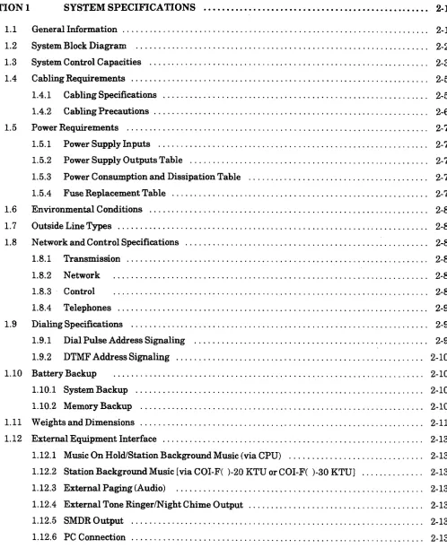
OF CONTENTS
SECTION 1 INTRODUCTION . . . l-l
1.1 Electra Professional 120 ... l-l 1.2 Electra Profession1 Level II and Level II Advanced ... l-3 1.3 RegulatoryInformation ... l-4 1.3.1 Company Notification ... l-5 1.3.2 BatteryDisposal ... l-6 1.3.3 IncidenceofHarm ... l-7 1.3.4 Radio Frequency Interference ... l-7 1.3.5 Hearing Aid Compatibility ... l-7 1.3.6 Direct Inward Dialing ... l-7 1.3.7 Voice Announcement/Monitoring Over DID Lines ... l-8 1.3.8 MusicOnHold ... l-8 1.3.9 Service Requirements ... l-8 1.3.10 UL Regulatory Information ... l-8 1.3.11 ICRequirements ... l-9 1.4 EquipmentList ... l-10 1.5 Equipment General Information ... l-16 1.6 Equipment Description - Electra Professional 12OILevel II/Level II Advanced ... l-16 1.6.1 Electra Professional 120 Key Service Units and Power Supply Units ... 1-16 1.6.2 Electra Professional Level II Key Service Units and Power Supply Units ... 1-16 1.6.3 Electra Professional Level II Advanced Key Service Units and Power Supply Units ... l-17 1.6.4 Common Control Key Telephone Unit ... 1-17 1.6.5 Station Interface Key Telephone Units ... .: ... l-18
1.6.6 Trunk Interface Key Telephone Units ... l-18 1.6.7 Optional Key Telephone Units ... l-20 1.6.8 Electra Elite Digital Multiline Terminals,Electra Professional Multiline Terminal, Single
LIST OF FIGURES
l-1 Outside View of the Electra Professional 120 KSUs . . . . . . 1-l x. l-2
l-3
l-4
Outside View of the 3Cabinet Electra Professional 120 KSUs ... l-2 :” Outside View of the Electra Profession Level II KSUs ... l-3
Outside View of the Electra Professional Level II Advanced KSUs ... l-4
LIST OF TABLES
l-l
l-2
l-3
l-4
l-5
l-6
l-7
l-8
l-9
l-10
l-11
l-12
l-13
FIC,REN,SOC,andJackTypesforKTUs ... Battery Types and Quantities for KSUs and KTUs ... Electra Professional 120 KSUs and PSUs ... Level II KSUs and PSUs ...
Level II Advanced KSUs and PSUs ...
Electra Professional 120 Common Control KTUs ...
. . . ,
. . . ,
. . .
...
l-5
,
CHAPTER
1
INTRODUCTION
SECTION 1 INTRODUCTION
1.1 Electra Professional 120
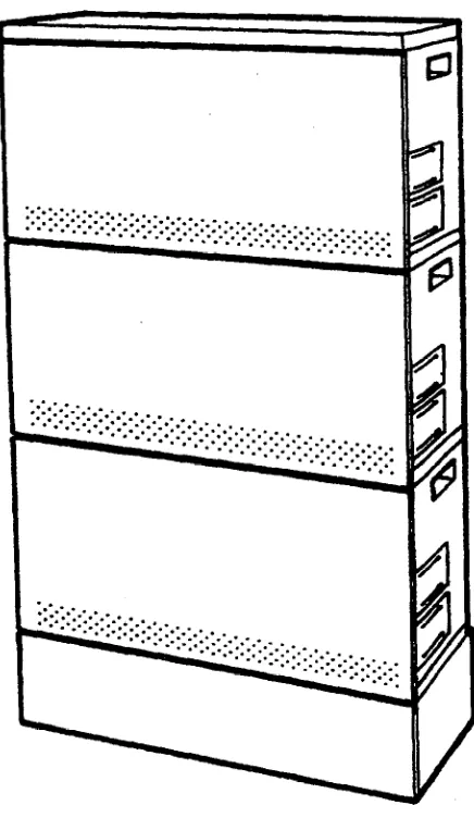
The Electra Professional 120 basic cabinet serves a combined total of 40 ports, consisting of outside lines, terminals, or other options. This system can be expanded to accommodate a combined total of 120 ports. The two expansion KSUs support up to 40 universal ports each. Additional equipment (such as Single Line Telephones, external speakers, voice mail, or facsimile machines1 can be connected to this system to enhance its abilities. Refer to Figure l-1 - Outside View of the Electra Professional 120 KSU and Figure l-2 - Outside View of the 3-Cabinet Electra Professional 120 KSUs.
This chapter provides the technician, installing the Electra Professional 120, a
comprehensive explanation of the system specifications, hardware, and installation procedures. The technician should understand this entire chapter before installing the system to enable more effkient installation and cut-over.
Figure l-2 Outside View of the 3Cabinet Electra Professional 120 KSUs 1.2 Electra Professional Level II and Level II Advanced
Installation Service M
This chapter provides the technician, installing the Electra Professional Level II or Level II Advanced, a comprehensive explanation of the systems specifications, hardware, and installation procedures. The technician should understand this entire chapter before installing the system to enable more efficient installation and cut-over.
Febrwe Electra Professional l%O/Level II/ Level II Advanced
Figure l-4 Outside View of the Electra Professional Level II Advanced KSUs 1.3 Regulatory Information
The Federal Communications Commission (FCC) has established rules that permit this telephone system to be directly connected to the telephone network. A jack is provided by the telephone company. Jacks are not provided on party lines or coin lines.
Installation Service Manual Electra Professional 12OILevel II /Level II Advanced February 1998 1.3.1 Company Notification
Before connecting this telephone system to the telephone network, the following information must be provided to the telephone company:
1. Your telephone number. 2. FCC registration number:
l If the system is to be installed as a Key System (no dial access to
Trunk Groups/Route Advance Blocks), use the following number: Electra Professional 120 AY5USA-25003-KF-E
Level II System: AY5USA-73702-KF-E Level II Advanced: AY5USA-74750-KF-E
0 If the system is to be installed as a Multifunction System, use the following number:
Electra Professional 120 AY5USA-25004-MF-E Level II System: AY5USA-73705-MF-E Level II Advanced: AY5USA-74743-MF-E
3. Facility Interface Codes (FIG), Ringer Equivalence Number (REN), Service Order Codes (SOC), and Jack types are shown in Table l-1 - FIC, REN, SOC, and Jack Types for KTUs.
Table l-l FIC, REN, SOC, and Jack Types for KTUs Interface KTU Type
1.3.2 Battery Disposal
The Electra Professional 120/Level II/Level II Advanced systems include the batteries listed in Table 1-2 - Battery Types and Quantities for KSUs and
KTUs. When disposing of these batteries, KSUs, or KTUs, you must comply ‘?., with applicable federal and state regulations regarding proper disposal . . .J’ procedures.
Table l-2 Battery Types and Quantities for KSUs and KTUs
MIF-F(A)-10 KTU Lithium 1
MIF-F(C)-10 KTU Lithium 1
MIF-F(U)-10 KTU Lithium
1
ETW-4R-l(BK) TEL NiCad 1
IMPORTANT SAFEGUARDS FOR BATTERY DISPOSAL
DO NOT PLACE USED BATTERIES IN REGULAR TRASH! THE PRODUCT YOU PURCHASED CONTAINS A NICKEL-CADMIUM OR SEALED LEAD BATTERY. NICKEL-CADMIUM OR SEALED LEAD BATTERIES MUST BE
COLLECTED, RECYCLED, OR DISPOSED OF IN AN
ENVIRONMENTALLY SOUND MANNER.
The incineration, landfilling or mixing of nickel-cadmium or sealed lead batteries with the municipal solid waste stream is PROHIBITED BY LAW in most areas. Contact your local solid waste management officials for other information regarding the environmentally sound collection, recycling, and disposal of the battery.
Nickel-cadmium (or sealed lead) batteries must be returned to a federal or state approved nickel-cadmium (or sealed lead) battery recycler. This may be where the batteries were originally sold or a local seller of automotive batteries. In Minnesota call l-800-225-PRBA if further disposal information is required, or call l-800-232-9632 for further information.
Installation Service Manual Electra Professional 120/Level II /Level II Advanced - February 1998
PRODUCT PACKAGE LABELING
F
a
CONTAINS NICKEL-CADMIUM BATTERY.Q@
MUST BE RECYCLED OR DISPOSED OF
PROPERLY. MUST NOT BE DISPOSED OF IN MUNICIPAL WASTE.
Ni-Cd
@ CONTAINS SEALED LEAD BATTERY.
w
MUST BE RECYCLED OR DISPOSED OF PROPERLY. MUST NOT BE DISPOSED OF IN MUNICIPAL WASTE.
Pb
1.3.3 Incidence of Harm
If the system malfunctions, it may also harm the telephone network. The telephone system should be disconnected until the source of the problem can be determined, and repair is made. If this is not done, the telephone company may temporarily disconnect service.
1.3.4 Radio Frequency Interference
In compliance with FCC Part 15 rules, the following statement is provided:
IMPORTANT NOTE
“This equipment generates, uses, and can radiate radio frequency energy and if not installed and used in accordance with the Installation Service Manual, may cause interference to radio communications. This equipment has been tested and approved for compliance with the limits for a Class A computing device pursuant to Subpart J of Part 15 of FCC Rules, that are designed to provide reasonable protection against such interference when operated in a commercial environment.
Operation of this telephone system in a residential area’ is likely to cause interference, in which case, the user, at his or her own expense, is required to take whatever measures are required to correct the interference. ”
1.3.5 Hearing Aid Compatibility
The NEC Multiline Terminals, Digital Multiline Terminals, and NEC Single Line Telephones provided for this system are hearing aid compatible. The manufacturer of other Single Line Telephones for use with the system must provide notice of hearing aid compatibility to comply with FCC rules. FCC rules prohibit the use of non-hearing aid compatible telephones (after August 16,1989).
1.3.6 Direct Inward Dialing
Y
Februar 1998
1.3.7
0 A call is unanswered.
l A busy tone is received.
0 A reorder tone is received.
Voice Announcement/Monitoring Over DID Lines
Using the Voice Announcement feature to eavesdrop or record sound activities at the other end of the telephone line may be illegal under certain circumstances and laws. Consult a legal advisor before implementing any practice involving the monitoring or recording of a telephone conversation. Some federal and state laws require a party monitoring or recording a telephone conversation to use a beep- tone(s), make notification to, and obtain consent of all parties to the telephone conversation. In monitoring or recording sound activities at the other end of the telephone line using the Voice Announcement feature, the sound of the alert tone at the beginning of the Voice Announcement may or may not be considered sufficient under applicable laws. Some of the applicable laws provide for strict penalties for illegal monitoring or recording of telephone conversations.
1.3.8 Music On Hold
“‘In accordance with U.S. Copyright Law, a license may be required from the American Society of Composers, Authors and Publishers, or other similar organization, if radio or TV broadcasts are transmitted through the Music On Hold feature of this telecommunication system. NEC America Inc., hereby
disclaims any liability arising out of the failure to obtain such a license.” 1.3.9
1.3.10
Service Requirements
If the equipment malfunctions, all repairs should be performed by an authorized agent of NEC America, Inc. or by NEC America, Inc. Users requiring service must report the need for service to an authorized agent of NEC America, Inc. or to NEC America, Inc.
UL Regulatory Information
This equipment is listed by Underwriters Laboratories and found to comply with all applicable requirements of the standard for telephone equipment UL 1459.
Proper answer supervision is provided when either of the following cases exist: A. This equipment returns answer supervision to the Public Switched
Telephone Network (PSTN) and Direct Inward Dialing (DID) calls are: 0 Answered by the called station.
l Answered by the Attendant.
0 Routed to a recorded announcement that can be administered by the Customer Premise Equipment (CPE) user.
0 Routed to a dial prompt.
B. This equipment returns answer supervision on all DID calls forwarded to the PSTN. Permissible exceptions are:
CAUTION
1.3.11 IC Requirements
Industry Canada has established rules that permit this telephone system to be directly connected to the telephone network. Prior to connecting or disconnecting this telephone system to or from the telephone network, the telephone company must be provided with the following information.
1. Your telephone number. 2. IC registration number:
3. The Load Number of the equipment: 9
The Industry Canada label identifies certified equipment. This certification means that the equipment meets certain telecommunications network protective operational and safety requirements. Industry Canada does not guarantee the equipment to operate to user satisfaction.
Before installing this equipment, users should ensure that it is permissible to be connected to the facilities of the local telecommunications company. The equipment must also be installed using an acceptable connection method. In some cases, the company inside wiring associated with a single line individual service may be extended by means of a certified connector assembly (telephone extension cord). The customer should be aware that compliance with the above conditions may not prevent degrading service in some situations.
Repairs to certified equipment should be made by an authorized Canadian maintenance facility designated by the supplier. Any repairs or alterations made by the user to this equipment, or equipment malfunctions, may give the telecommunications company cause to request the user to disconnect the equipment.
Users should ensure for their own protection that the electrical ground connections of the power utility, telephone lines, and internal metallic water pipe system, if present, are connected together. This precaution may be particularly important in rural areas.
CAUTION
Users should not attempt to make such connections themselves, but should contact the applicable electric inspection authority or electrician.
The Load Number (LN) assigned to each terminal device denotes the percentage of the total load to be connected to a telephone loop which is used by the device to prevent overloading. The termination on a loop may consist of any combination of devices subject only to the requirement that the load numbers total does not exceed 100.
This equipment meets IC requirements CS03.
Use of the LLT-F(BG)-10 KTU has not been approved by IC for support of
off-premise extensions. .--._ \ .1
‘-’ This digital apparatus does not exceed the Class A limits for radio noise emissions from digital apparatus as set out in the radio interference regulations of Industry Canada.
and
Le present appareil numerique n’emet pas de bruits radioelectriques depassant les limites applicables aux appareils numeriques de Classe A prescrites dans le
reglement sur le brouillage radioelectrique edicte par Industrie Canada. 1.4 Equipment List
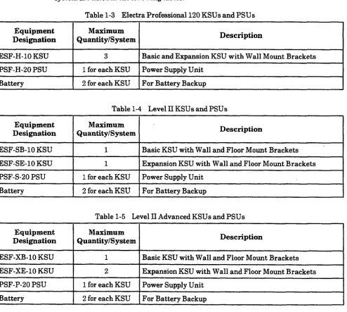
The following equipment is available for use in the Electra Professional 120/Level II/Level II Advanced systems. The maximum quantities that can be installed in each system are listed in the following tables.
Table 1-3 Electra Professional 120 KSUs and PSUs
Equipment Maximum
Designation Quantity/System Description
ESF-H-10 KSU PSF-H-20 PSU Battery
3 Basic and Expansion KSU with Wall Mount Brackets 1 for each KSU Power Supply Unit
2 for each KSU For Battery Backup
Table 1-4 Level II KSUs and PSUs
I
EquipmentI
Maximum
Designation Quantity/System Description I
ESF-SB-10 KSU ESF-SE-10 KSU PSF-S-20 PSU Battery
’ 1 Basic KSU with Wall and Floor Mount Brackets
1 Expansion KSU with Wall and Floor Mount Brackets 1 for each KSU Power Supply Unit
I
1 2 for each KSU 1 For Battery Backup I
Table l-5 Level II Advanced KSUs and PSUs Equipment
Designation ESF-XB-10 KSU ESF-XE-10 KSU PSF-P-20 PSU Battery
Maximum
Quantity/System Description
1 Basic KSU with Wall and Floor Mount Brackets 2 Expansion KSU with Wall and Floor Mount Brackets 1 for each KSU Power Supply Unit
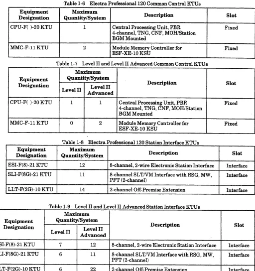
Table 1-6 Electra Professional 120 Common Control KTUs
Equipment Maximum
Designation Quantity/System Description Slot
CPU-F( j-20 KTU 1 Central Processing Unit, PBR Fixed
4-channel, TNG, CNF, MOH/Station BGM Mounted
MMC-F-11 KTU 2 Module Memory Controller for
ESF-XE- 10 KSU
Fixed
Table l-7 Level II and Level II Advanced Common Control KTUs Maximum
Equipment Quantity/System
Designation
Level II Level II
Description Slot
Advanced
CPU-F( j-20 KTU 1
1
Central Processing Unit, PBR Fixed4-channel, TNG, CNF, MOH/Station BGM Mounted
MMC-F-11 KTU 0 2 Module Memory Controller for Fixed
ESF-XE-10 KSU
Table l-8 Electra Professional 120 Station Interface KTUs Equipment
I
Masimum
Designation Quantity/System I Description
I
SlotESI-F(8)-21 KTU t 12 1 Ekhannel, 2-wire Electronic Station Interface Interface
SLI-F(8G)-21 KTU
11
8-channel SLTNM Interface with RSG, MW,PFT (2-channel) Interface
LLT-F(BG)-10 KTU 14 2-channel Off-Premise Extension Interface
Table l-9 Level II and Level II Advanced Station Interface KTUs Maximum
Equipment Quantity/System
Designation
Level II Level II
Description Slot
Advanced
ESI-F(8)-21 KTU 7 12 8-channel, 2-wire Electronic Station Interface Interface
SLI-F(8G)-21 KTU 6
11
8-channel SLTNM Interface with RSG, MW, InterfacePFT (2-channel)
KTU/Unit
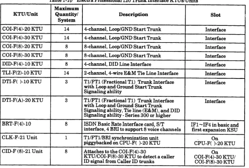
Table l-10 Electra Professional 120 Trimk Interface KTUs/Units
Table l-11 Level II and Level II Advanced Trunk Interface KTUsNnits Maximum
KTUAJnit Quantity/System Level II Advanced Level II
Description Slot
COI-F(4)-20 COI-F(4)-30 COI-F(8)-20 COI-F(8)-30 DID-F(4)-10 TLI-F(2)-10
DTI-F( j-10
DTI-F(A)-20
BRT-F(4)-10
kE-F-21
&F(8)-21
7 16 4-channel, Loop/GND Start Trunk Interface
7 16 4-channel, Loop/GND Start Trunk Interface
7 8 8-channel, Loop/GND Start Trunk Interface
7 8 8-channel, Loop/GND Start Trunk Interface
7 .8 4-channel, DID Line Interface Interface
7 16 2-channel, 4-wire E&M Tie Line Interface
2 3 Tl/FTl (Fractional Tl) Trunk Interface Interface
with Loop /Ground Start Trunk Signaling ability
2 3 Tl/FTl (Fractional Tl) Trunk Interface Interface
with Loop /Ground Start Trunk, Tie line (E&M), and DID Signaling ability - Series 300 or higher
4 8 ISDN Basic Rate Interface card, S/T IF1 -IF4 in basic and interface, 4 BRI to support 8 voice
channels first expansion KSU
1 1 Tl/FTl/BRI sunchronization unit
piggybacked on CPU-F( j-20 KTU CPU-F(?20 KTU
4 8 Attaches to the COI-F(4)-30
KTWCOI-F(8)-30 KTU to detect a caller COI-F(4?:0 KTU/ ID signal from Caller ID trunks COI-F(8)-30 KTU
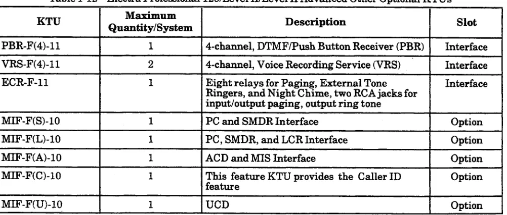
Table 1-12 Electra Professional 12OILevel II/Level II Advanced Other Optional KTUs
I
MIF-F(A)-10I
MIF-F(C)-10Maximum
Quantity/System I Description
I
Slot1
I
4-channel, DTMF/Push Button Receiver (PBR) Interface Interface InterfaceOption
1 PC, SMDR, and LCR Interface Option
1 ACD and MIS Interface Option
This feature KTU provides the Caller ID feature
UCD
Februarv 1998 Electra Professional 12OILevel II /Level II Advanced Installation Service Manual Table l-13 Electra Professional 12O/Level II/level II Advanced Terminals and Optional Units
Maximum Quantity/System
Equipment Designation 1201 Description
Level II Level II Advanced
ETW-8-( ) (BK) TEL 55 95 8-line non-display with built-in speakerphone, large
ETW-8-c ) (SW) TEL LED, eight function keys, ADA compatible, and comes
in black or soft white
ETW-16DC-( 1 (BK) TEL 56 96 16-line Display Compact with built-in speakerphone,
ETW-16DC-( ) (SW) TEL large LED, eight function keys, ADA compatible, and
comes in black or soft white
ETW-16DD-( > (BK) TEL 56 96 16-line Display Deluxe with built-in speakerphone,
ETW-16DD-( 1 (SW) TEL large LED, eight function keys, 20 programmable
One-Touch keys with red LEDs, ADA compatible, and comes in black or soft white
ETW-24DS-( ) (BK) TEL 56 96 24-line Display Special with built-in speakerphone,
ETW-24DS-( 1 (SW) TEL dual path ability, Large LED, eight function keys, 12
programmable One-Touch keys, ADA compatible, and comes in black or soft white
and comes in black or soft white
TEL
d 16 Programmable line Keys with two-
DTU-32D-( ) (BKY(WH) Digital Multiline Terminal lectra Elite with
TEL display and 32 Programmable line Keys with two-
color LED ADA(l)-W (BK) TEL
ADA(l)-W (SW) TEL
56 96 Ancillary Device Adapter (for connection of headset, recording interface, or external speakerphone) that comes in black or soft white
ADA(B)-W (BK) TEL ADA(2)-W (SW) TEL
16 16 Ancillary Device Adapter (for connection of an SLT, Modem, answering machine, or fax) that comes in black or soft white. Additional units may be possible depending on traffic and number of available PBR circuits.
Table 1-13 Electra Pro
I---
Equipment Designation
APR-U 16 16
r
HFU-U1 SLT-F(lG)-10 ADP
essional12O/Level II/level II Advanced Terminals and Optional Units (Continued) Maximum
Quantity/System
1201 Description
Level II Level II Advanced
Electra. Elite Analog Port Ringing Adapter. Additional units may be possible depending on traffic and number of available PBR circuits.
56 96 Electra Elite Handsfree Unit
56 96 Electra Elite Wall Mount Unit
56 96 Wall Mount Unit that comes in black or soft white
55 I 95 I - 1 channel Single Line Telephone Adapter
1.5 Equipment General Information
One Electra-Professional 120/Level IVLevel II Advanced Job Specifications Manual is included with the CPU-F( j-20 KTU All optional equipment: external amplifiers, Music
On Hold source, Background Music source, or external speakers must be locally provided. .” .> _r 1.6 Equipment Description - Electra Professional l%O/Level II/Level II Advanced
1.6.1 Electra Professional 120 Key Service and Power Supply Units ESF-H-10 KSU
The Key Service Unit (KSU) of the Electra Professional 120 system provides service for outside lines, Attendant Consoles, and interconnection of Multiline Terminals. The basic KSU provides 40 ports. (The 40 ports are available with five interface slots. An application slot is also available but does not affect the port count.) The KSU can be expanded to 120 ports by vertically stacking two additional ESF-H-10 KSUs on the existing KSU. Each KSU provides 40 ports. A PSF-H-20 PSU (Power Supply Unit) and backup batteries are included with each KSU.
Fixed slots are intended for the CPU, MMC, and MIF KTUs. The remaining interface slots are intended for 2-, 4-, or &channel KTUs: ESI, SLI, COI, DID, TLI, PBR, VRS, ECR, LLT, BRT, and DTI.
PSF-H-20 PSU
This power supply unit is provided with both the basic and expansion KSUs. It has a backup interface, accepts 117 Vat and outputs + 5V, -5V, and -24V to the system.
1.6.2 Electra Professional Level II Key Service and Power Supply Units ESF-SB-10 KSU
The Key Service Unit (KSU) of the system provides service for outside lines, Attendant Add-On Consoles, and interconnection of Multiline Terminals. The basic KSU provides 40 ports. (The 40 ports are available with five interface slots. An application slot is also available but does not affect the port count.) The KSU can be expanded to 64 ports with an expansion module. A PSF-S-20 PSU Power Supply Unit and backup batteries are included with this KSU. Fixed slots are intended for the CPU and MIF KTUs. Theremaining interface slots are intended for 2-, 4-, or 8-channel KTUs: ESI, SLI, COI, DID, TLI, PBR, VRS, ECR, LLT, BRT, DTI.
ESF-SE-10 KSU
This expansion unit provides for an additional 24 ports that can accommodate up to three KTUs.
This KSU is designed to accommodate 2-, 4-, or 8-channel interface cards. A PSF-S-20 PSU (Power Supply Unit) and backup batteries are included with this KSU.
PSF-S-20 PSU
1.6.3 Electra Professional Level II Advanced Key Service and Power Supply Units ESF-XB-ID KSU
The Key Service Unit (KSU) of the Electra Professional Level II Advanced system provides service for outside lines, Attendant Add-On Consoles, and interconnection of Multiline Terminals. The basic KSU provides 64 ports and can be expanded in 64-port increments up to 192 ports with expansion modules. A PSF-P-20 PSU Power Supply Unit and backup batteries are included with this KSU.
Fixed slots are intended for the CPU and MIF KTUs. The remaining interface slots are intended for 2-, 4-, or 8-channel KTUs: ESI, SLI, COI, DID, TLI, PBR, VRS, ECR, LLT, DTI. (Up to two DTIs can be installed in this KSU.)
ESF-XE-10 KSU
This Level II Advanced system expansion unit provides for an additional 64 ports that can accommodate up to 8 KTUs. Fixed slots are intended for the MMC and MIF KTUs.
This KSU accommodates 2-, 4-, or 8-channel interface cards. A PSF-P-20 PSU Power Supply Unit and backup batteries are included with this KSU.
PSF-P-20 PSU
This power supply unit is provided with both the basic and expansion KSUs. It supports the 64 ports in each KSU, has a backup interface, accepts 117 Vat and outputs + 5V, -5V, and -24V to the system.
1.6.4 Common Control Key Telephone Unit
These units are used with the 120, Level II, and Level II Advanced systems. CPU-F( J-20 KTU
The Central Processing Unit KTU contains a 16-bit microprocessor that has overall control of the system. This KTU provides an advanced feature package for the system user. Included with this KTU are six 4-party conference circuits, four PBR circuits, TNG, MOH input, and a built-in music source. A CLK-F-21 Unit can be installed on the CPU as an option. A maximum of one CPU-F-( l-20 KTU can be installed in the system.
CLK-F-21 Unit
The CLK-F-21 (Clock) Unit provides synchronization for a Tl and/or ISDN line that is connected to the system. This unit is attached to the CPU-F( l-20 KTU and works in conjunction with the DTI-F( j-10 KTU, DTI-F(A)-20 KTU, or BRT- F(4)-10 KTU. A maximum of one CLK-F-21 Unit can be installed in the system. MMC-F-11 KTU
1.6.5
1.6.6
CID-F@)-21 Unit
This Unit is piggybacked on the CO1 -F(4)-30 or CO1 -F(8)-30KTU. It is used to detect a Caller ID signal from Caller ID trunks.
This unit is not required when the BRT-F(4)-10 KTU is installed. Station Interface Key Telephone Units
ESI-F(8)-21 KTU
This Electronic Station Interface KTU contains eight circuits; each can support any Multiline Terminal, EDW-48-t 1 (BK>/(SW) Console, DCU-60-l ) (BK)/(WH) Console, an SLT Adapter, or Dterm Cordless Terminal.
A maximum of 12 ESI-F(8)-21 KTUs can be installed in the 12OILevel II Advanced interface slots. A maximum of seven can be installed in Level II. SLI-F@G)-21 KTU
The Single Line Interface KTU can support eight Single Line Telephones and/or voice-mail ports. This KTU provides Ringing Signal Generator (RSG), Power Failure Transfer (PFT), and Message Waiting (MW) LED voltage to the Single Line Telephones.
A maximum of 11 SLI-F(8G)-21 KTUs can be installed in the 12OILevel II Advanced system interface slots. A maximum of six can be installed in Level II. LLT-F(BG)-10 KTU
The Long Line Telephone (LLT) KTU provides for the termination and operation of up to two Off-Premise Extensions (OPX). Each LLT-F(BG)-10 KTU has a built-in ringer (RSG). Up to 1500 ohms of loop resistance (including the Single Line Instrument) is acceptable between the LLT-F(BG)-10 KTU and SLT. A maximum of 13 LLT-F(BG)-10 KTUs can be installed in the 120 system interface slots. A maximum of 22 can be installed in Level II advanced system, and a maximum of six, in Level II system.
Trunk Interface Key Telephone Units
These units are compatible with the 120, Level II, and Level II Advanced systems
BRT-F(4)-10 KTU
The Basic Rate Trunk Interface (BRT) KTU provides termination of ISDN basic-rate trunk lines. This unit supports four ISDN-BRI trunks; each trunk supports two channels. These eight channels can be used for CO trunks. Tip and Ring electrical fuses are provided to comply with UL 1459 requirements. One BRT KTU provides a maximum of two lines.
The BRT uses an S-type interface. When connecting to a CO, a locally provided Network Termination (NTl) unit is required.
COI-F(4)-20 KTU
This Central Office Interface KTU complies with UL 1459 requirements. Electrical fuses (posistors) are built into this KTU. The COI-F(4)-20 KTU supports four outside (CO/PBX) lines. The outside lines can be any combination of Loop/Ground start, DTMF, or Dial Pulse dialing trunks.
A maximum of 14 COI-F(4)-20 KTUs can be installed in the 120 system interface slots. A maximum of 16 can be installed in Level II advanced, and a maximum of seven, in Level II.
COI-F(4)-30 KTU
This Central Office Interface KTU complies with UL 1459 requirements. Electrical fuses (posistors) are built into this KTU. The COI-F(4)-30
KTU
supports four outside (CO/PBX) lines. The outside lines can be any combination of Loop/Ground start, DTMF, or Dial Pulse dialing trunks. This KTU also provides Caller ID trunk interface.A maximum of 14 COI-F(4)-30 KTUs can be installed in the 120 system interface slots. A maximum of 16 can be installed in Level II advanced, and a maximum of seven, in Level II.
COI-F(S)-20 KTU
This Central Office Interface KTU complies with UL 1459 requirements. Electrical fuses (posistors) are built into this KTU. The COI-F(S)-20 KTU
supports eight outside (CO/PBX) lines. The outside lines can be any combination of Loop/Ground Start, DTMF, or Dial Pulse dialing trunks.
A maximum of eight COI-F(8)-20 KTUs can be installed in the 12OILevel II Advanced system interface slots. A maximum of seven can be installed in Level II.
COI-F(8)-30 KTU
This Central Office Interface KTU complies with UL 1459 requirements. Electrical fuses (posistors) are built into this KTU. The COI-F(8)-30 KTU
supports eight outside (CO/PBX) lines. The outside lines can be any combination of Loop/Ground Start, DTMF, or Dial Pulse dialing trunks. This KTU also provides Caller ID trunk interface.
A maximum of eight COI-F(8)-30 KTUs can be installed in the 120/Level II Advanced system interface slots. A maximum of seven can be installed in Level II.
DID-F(4)-10 KTU
The Direct Inward Dialing interface KTU complies with UL 1459 2nd Edition requirements. The DID-F(4)-10 KTU supports the termination and operation of up to four DID lines. Electrical fuses (posistors) are built into this KTU. Immediate start, wink start, and delay dial are accommodated. Dial Pulse and
DTMF are supported.
TLI-F(2)-11 KTU
This Tie Line Interface KTU supports the termination and operation of up to two E&M Tie Lines (4-wire, type I and type V, and lo/20 pps Dial Pulse or DTMF). Immediate or wink start, delay start, or second dial tone signaling is accommodated.
- --.,;>, i’ A maximum of 14 TLI-F(B)-11 KTUs can be installed in the 120 system interface slots. A maximum of 16 can be installed in the Level II advanced system, and a maximum of seven, in the Level II.
DTI-F( j-10 KTU
The Digital Trunk Interface (DTI) KTU provides for the termination of a Tl/Fractional Tl (24 DS-0 channels or fewer) line. The DTI-F( j-10 KTU contains circuitry for outside ring detection, hold, dialing, and control functions. A combination of Loop/Ground Start Trunks can be used on one DTI. DTMF or Dial Pulse dialing is also supported.
The two interface slots to the right of this KTU may need to be left vacant. A CLK-F-21 Unit must be connected to the CPU-BY j-20 KTU.
Three DTI-F( J-10 or -20 KTUs can be installed in the 12OILevel II Advanced system. One can be installed in Level II.
DTI-F(A)-20 KTU
This Digital Trunk Interface (DTI) KTU includes the functions of the DTI-F( j-10 KTU in addition to Tie line (E&M) and DID signaling abilities. A combination, in groups of four, of Loop/Ground Start Trunks, Tie lines, or DID Trunks can be used on one DTI KTU. DTMF or Dial Pulse dialing is also supported.
The two interface slots to the right of this KTU may need to be left vacant depending on System Programming. A CJLK-F-21 Unit must be connected to the CPU-F( j-20 KTU.
Three DTI-F(A)-20 or -10 KTUs can be installed in the 12OILevel II Advanced system. One can be installed in Level II.
1.6.7 Optional Key Telephone Units ECR-F-11 KTU
The External Control Relay (ECR) KTU provides common audible tone signaling with relay contacts for external ringing equipment, Eight relays are provided, four for External Tone Ringer control, one for Night Chime, and three for External Paging.
PBR-F(4)-11 KTU
The Push Button Receiver KTU detects and translates DTMF tones generated by Single Line Telephones, modems, or facsimile machines. The PBR-F(4)-11 KTU provides four circuits.
One PBR-F(4)-11 KTU can be installed in the 120/Level II/Level II Advanced system for a maximum of eight circuits per system with a CPU-F( j-20 KTU. VRS-F(4)-11 K’l’U
The Voice Recording Service KTU provides automatic answering of incoming CO/PBX calls by a voice recorded message, the voice prompt feature, and Delay Announcement for the ACD and UCD features.
A maximum of two VRS-F(4)-11 KTUs can be installed in interface slots providing eight channels..
MIF-F(S)-10 KTU
This Multipurpose Interface KTU has two abilities: it allows the connection of a personal computer to perform system programming and up/down System Data loading and provides Station Message Detail Recording (SMDR) to be output through an RS-232 cable to a printer.
One MB?-F(S)-10 KTU can be installed in the option slot or any of the first four interface slots (IFl/OPl - IF4/OP4) provided in the ESF-H-10 KSU, ESF-SB-10 KSU, or the fast ESF-XE-10 KSU installed.
MIF-F(L)-10 KTU
This Multipurpose Interface KTU has three abilities: it allows the connection of a personal computer to perform System Programming and up/down System Data loading, provides Station Message Detail Recording (SMDR) to be output through an RS-232 cable to a printer, and provides Least Cost Routing (LCR). One MIF-F(L)-10 KTU can be installed in the option slot or any of the first four interface slots (IFl/OPl - IF4/OP4) provided in the ESF-H-10 KSU, ESF-SB-10 KSU, ESF-XB-10 KTU, or the first ESF-XE-10 KSU installed.
Refer to the Electra Professional 120/Level II/Level II Advanced Least Cost Routing Manual (included with the LCR software) for LCR instructions.
MIF-F(A)-10 KTU
The MIF-F(A)-10 KTU provides the Automatic Call Distribution (ACD) feature and an interface to an MIS (ACD) terminal.
Februarv 1998 Electra Professional 12O/Level II /Level II Advanced Installation Service Manual MIF-Ft.-U)-10 KTU
The I&IF-F(U)-10 KTU provides the Uniform Call Distribution WCD) feature. One MIF-F(U)-10 KTU can be installed in the option slot or any of the first four interface slots (IFl/OPl - IF4/OP4) provided in the ESF-H-10 KSU, ESF-SB-10 KSU, the ESF-XB-10 KTU, or the Srst ESF-XE-10 KSU installed.
MIF-F(C)-10 KTU
This KTU provides the Caller ID Indication feature. A Scroll key is available to display the last 10 incoming Caller IDS. Press the scroll key repeatedly to display additional Caller ID names or numbers,.
One MIF-F(C)-10 KTU can be installed in the option slot or any of the first four interface slots (IFl/OPl - IF4/OP4) provided in the ESF-H-10 KSU, ESF-SB-10 KSU, ESF-XB-10 KTU, or the fast ESF-XE-10 KSU installed.
1.6.8 Electra Elite Digital Multiline Terminals, Electra Professional Multiline Terminals, Single Line Telephones, and Associated Equipment
DTUd-( 1 (BKY(WH) TEL
This non-display Digital Multiline Terminal has eight programmable line keys (each with a two-color LED), built-in speakerphone, headset jack, a Large LED to indicate incoming calls and messages, and compatibility with the ADA-U, APR-U , and HFU-U Units. This terminal comes in black or white.
A combined maximum of 96 Electra Professional and Electra Elite digital terminals can be installed in the 12O/Level II Advanced system. The maximum for Level II is 56.
DTU-164 ) (BKY(WH) TEL
This non-display Digital Multiline Terminal has 16 programmable line keys (each with a two-color LED), built-in speakerphone, a Large LED to indicate incoming calls and messages, and compatibility with the ADA-U, APR-U, and HFU-U Units. This terminal comes in black or white.
A combined maximum of 96 Electra Professional and Electra Elite digital terminals can be installed in the 12O/Level II Advanced system. The maximum
for Level II is 56, h
DTU-16D-(1 ) (BKV(WH) TEL
This display Digital Multiline Terminal has 16 programmable line keys (each with a two-color LED), built-in speakerphone, a Large LED to indicate incoming calls and messages, and compatibility with the ADA-U, APR-U, and HFU-U Units. This terminal comes in black or white.
The adjustable LCD (Liquid Crystal Display) has 24 characters and 3 lines. A combined maximum of 96 Electra Professional and Electra Elite digital terminals can be installed in the 120/Level II Advanced system. The maximum for Level II is 56.
DTU-16D42 1 (BKY(WH) TEL
DTU-324 1 (BKMWH) TEL
This non-display Digital Multiline Terminal has 32 programmable line keys (each with a two-color LED), built-in speakerphone, a Large LED to indicate incoming calls and messages, and compatibility with the ADA-U, APR-U, and HFU-U Units. This terminal comes in black or white.
A combined maximum of 96 Electra Professional and Electra Elite digital terminals can be installed in the 120/Level II Advanced system. The maximum for Level II is 56.
DTU-32D-(1) (BKMWH) TEL
This display Digital Multiline Terminal has 32 programmable line keys (each with a two-color LED), built-in speakerphone, a Large LED to indicate incoming calls and messages, and compatibility with the ADA-U, APR-U, and HFU-U Units. This terminal comes in black or white.
The adjustable LCD (Liquid Crystal Display) has 24 characters and 3 lines. A combined maximum of 96 Electra Professional and Electra Elite digital terminals can be installed in the 12OILevel II Advanced system. The maximum for Level II is 56.
DTU-32D42) (BKV(WH) TEL
This display Digital Multiline Terminal is used with Series 650 and higher and differs from the DTU-32D-(1) only by the addition of four softkeys.
DCU-60-C 1 (BK)/(WH) CONSOLE
The Attendant Console has 60 programmable line keys (each with a two-color, red or green, LED). The first 48 line keys can be programmed as Direct Station Selection keys or as outside line keys; the remaining 12 line keys can be programmed for features such as Paging, Night Transfer, or Message Waiting. An external power supply (AC Adapter) is required and is included with the Attendant Console.
A maximum of four consoles can be installed in the Electra Professional 12OILevel II/Level II Advanced system. An attendant position can have two attached consoles. (This console cannot be installed on the Electra Professional Level I system.)
ETW-8-t 1 (BKMSW) TEL
This Multiline Terminal is a fully modular instrument with tilt stand, eight Flexible Line keys (each with a two-color, LED), eight function keys, built-in speakerphone, ADA compatibility, and a large LED to indicate incoming calls and messages.
ETW-16DC-( 1 (BKY(SW) TEL
This Multiline Terminal is a fully modular instrument with tilt strand, 16 Flexible Line keys (each with a two-color LED), eight function keys, built-in speakerphone, a 16~character by two-line Liquid Crystal Display (LCD), ADA compatibility, and a large LED to indicate incoming calls and messages.
A maximum of 96 ETW-16DC-( > (BKHSW) TELs can be installed in Electra Professional 120/Level II Advanced slots. A maximum of 56 can be installed in Level II.
ETW-16DD-( 1 (BKY(SW) TEL
This Multiline Terminal is a fully modular instrument with 16 Flexible Line keys (each with a two-color LED), eight function keys, built-in speakerphone, a 16-character by 2-Line Liquid Crystal Display (LCD), 20 programmable One- Touch keys with red LED, ADA compatibility, and a large LED to indicate incoming calls and messages.
A maximum of 96 ETW-16DD-( ) (BKY(SW) TELs can be installed.in Electra Professional 120/Level II Advanced slots. A maximum of 56 can be installed in Level II.
ETW-24DS-( 1 (BKY(SW) TEL
This Multiline Terminal is a fully modular instrument with 24 Flexible Line keys (each with a two-color LED), eight function keys, built-in speakerphone, dual path ability,a 16-character by 2-Line Liquid Crystal Display (LCD), 12 programmable One-Touch keys, ADA compatibility, and a large LED to indicate incoming calls and messages.
A maximum of 96 ETW-24DS-( > (BK)/(SW) TELs can be installed.in Electra Professional 12OILevel II Advanced slots. A maximum of 56 can be installed in Level II.
EDW-48-t 1 (BKMSW) Console
The Attendant Add-On Console has a tilt stand, 48 programmable keys with two LEDs (red or green) and 12 function keys with red LED. The 48 programmable keys can be assigned as Direct Station Selection keys, outside line keys, or function keys.
A maximum of four EDW-48-t ) (BK)/(SW) Consoles can be installed.in Electra Professional 1201Level II/Level II Advanced slots.
ETW-4R-( 1 (BK) TEL
A black ETW-4R-1 TEL, Dt erm Cordless Terminal, can be connected to the Electra Professional 12OILevel II/Level II Advanced system using an ES1 port. This terminal has a cordless handset, a lo-digit by 2-line LCD, dial pad, TALK key, HOLD key, TRF key, CNF key, SPD key, MSG LED, buzzer, and four function keys with red LED. The Dt crm Cordless Terminal can be switched to the Multiline Terminal that is connected to it by pressing the DESK key on the base unit of the idle
Dt-
Cordless Terminal.A maximum of nine ETW4R-( > (BK) TEL
Dterm
Cordless Terminals is recommended for any system.Lamp. Each terminal requires one port of an SLI-F@G)-21 KTU, LLT-F(2Q-10 KTU, SLT-F(lG)-20 ADP, or SLT-F(lG)-10 ADP.
ETJ-lHM-1 (SW) TEL
This Single-Line Telephone is a fully modularized terminal with a Flash key, Redial key, three-level ring volume control, data jack, Message Waiting Lamp, and eight programmable Feature/Speed Dial keys. Each terminal requires one port of an SLI-F@Gl-21 KTU, LLT-F(2G)-10 KTU, SLT-F(lG)-20 ADP, or SLT- F(lG)-10 ADP.
ADA(l)-W (BKNSW) Unit
This unit (Ancillary Device Adapter) provides the Multiline Terminal with connection for a headset, external speakerphone, or tape recorder. This unit can be installed in any Electra Professional Multiline Terminal.
A maximum of 96 ADA(l)-W (BKY(SW) Units can be installed in the Electra Professional 1201Level II Advanced slots (one per Multiline Terminal). A maximum of 56 can be installed in Level II.
ADA(B)-W (BKNSW) Unit
The ADA(B)-W (BKY(SW) Unit (Ancillary Device Adapter) provides the Multiline Terminal with connection for a Single Line Telephone, Fax, answering machine or modem. This unit can be installed in any Electra Professional Multiline Terminal.
A maximum of 96 ADA(l)-W (BKYCSW) or ADA(B)-W (BKY(SW) units can be installed in the Electra Professional 1201Level II Advanced slots. A maximum of 56 can be installed in Level II. The maximum number of ADA(B)-W (BK)/(SW) Units installed depends on system traf?ic and the number of PBR circuits available.
ADA-U Unit
Ancillary Device Adapters allow connection of a tape recorder for logging/recording telephone calls to Electra Elite Digital Multiline Terminals. The ADA-U Unit does not require an AC adapter (ACA-U).
One ADA-U Unit can be installed on an Electra Elite Digital Multiline Terminal.
APR-U Unit
The Analog Port Adapter with Ringing provides an interface for installing Single Line Telephones, modems, and NEC VoicePointNoicePoint Plus Conferencing unit. The APR-U Unit also detects incoming ringing signals. By providing ring detection, the user can install a personal fax machine or an answering machine for convenience. Two user-adjustable switches are provided on the adapter: SW3 allows for 600 ohms or a complex impedance interface to devices such as a modem or Single Line Telephone, and SW1 is set to position 2 (the Electra Professional systems do not support the B2 channel).
The APR-U requires an AC Adapter (ACA-U) that is ordered separately. If an APR-U and HFU-U are both installed, only one ACA-U is required.
HFU-U Unit
The Handsfree Unit provides a solution for small office teleconferencing by improving the sound quality of speakerphone calls using an external
microphone. This unit is useful in a working environment where handsfree -.-, calling is necessary. To provide maximum performance, two user-adjustablt j switches are available that allow the speakerphone to be configured for the :’ customer environment (quiet room, noisy business environment, or a room with an acoustic echo). A push-to-mute button on the external microphone adds privacy for handsfree dialing.
The HFU-U requires an AC Adapter (ACA-U) that is ordered separately. If an APR-U and HFU-U are both installed, only one AC Adapter is required.
One HFU-U Unit can be installed on an Electra Elite Digital Multiline Terminal.
Note: This unit enhances the handsfree operation of a Digital Multiline Terminal by providing an echo canceling circuit. However, this unit is primarily for a typical small office environment and not for conference rooms. Its performance should not be compared to commercial audio conference units. Also, calls may not be recorded when using the HFU-U.
WMU-U (BKY(SW1 Unit
Wall Mount Unit accommodates adapters that are installed on the Electra Elite Digital Multiline Terminal.
WMU-W (BKY(SW) Unit
This unit is a universal Wall Mount Unit that can be used to mount any Electra Professional Multiline Terminal and comes in black or soft white.
1.6.9 Single Line Telephone Adapters SLT-F(lGl-10 ADP
This Single-Line Telephone Adapter provides an interface for a Single-Line Telephone or similar device from an ESI-F(8)-21 KTU channel.
A maximum of 95 SLT-F(lG)-10 ADP adapters can be installed in Electra Professional 120/Level II Advanced slots. A maximum of 55 can be installed in Level II.
SLT-F(lGl-20 ADP
This Single-Line Telephone Adapter provides an interface for a Single-Line Telephone or similar device from an ESI-F(8)-21 KTU channel.
CHAPTER
2
ELECTRA
PROFESSIONAL
120
HARDWARE
SPECIFICATIONS
Installation Service Manual Electra Professional /ruary 1201Level II/Level II Advanced 1998
ELECTRA
PROFESSIONAL
120
HARDWARE
SPECIFICATIONS
AND INSTALLATION
TABLE
OF CONTENTS
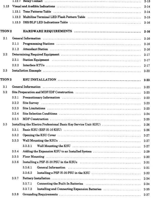
SECTION 1 SYSTEM SPECIFICATIONS . . . . . . . 2-1 1.1
1.2 1.3 1.4
1.5
1.6 1.7 1.8
1.9
1.10
1.11 1.12
1.12.7 Relay Contact ... 2-13 1.13 Visual and Audible Indications ... 2- 14
1.13.1 Tone Patterns Table ... 2-14 .--‘\
Multiline Terminal LED Flash Pattern Table 2
1.13.2 ... 2-15
1.13.3 DSS/BLF LED Indications Table ... 2-16
SECTION 2 HARDWARE REQUIREMENTS . . . . . . . 2-16 2.1 General Information ...
2.1.1 Programming Stations ... 2.1.2 Attendant Station ... 2.2 Determining Required Equipment ...
2.2.1 Station Equipment ... 2.2.2 Interface KTUs ... 2.3 Installation Example ...
... ... ... ... ... ... ... . . . . . . . .
. . 2-16 . . 2-16 . . 2-16 . . 2-17 . . 2-17 . . 2-17 . . 2-22
SECTION 4 INSTALLING A KEY TELEPHONE UNIT (KTU) . . . 2-38
4.1 GeneralInformation ... 2-38
4.1.1 Installation Precautions ... 2-38
4.1.2 KTU Installation ... 2-38
4.2 Common Control KTUs ... 2-39
4.2.1 CPU-F( )-20KTU ... 2-39
4.2.2 MMC-F-11KTU ... 2-43
4.3 InterfaceKTUs ... 2-45
4.3.1 ESI-F(g)-21 KTU ... 2-45
4.3.2 SLI-F@G)-21 KTU ... 2-46
4.3.2.1 Power Failure Backup ... 2-47
4.3.3 LLT-F(BG)-10 KTU ... 2-49
4.3.4 COI-F(4)-20 KTU and COI-F(4)-30 KTU ... 2-50
4.3.5 COI-F(8)-20 KTU and COI-F(8)-30 KTU ... 2-52
4.3.6 CID-F(8)-1 1 Unit ... 2-55
4.3.7 DID-F(4)-10 KTU ... 2-59
4.3.8 TLI-F(2)-10KTU ... 2-60
4.3.9 DTI-F( j-10 KTUIDTI-F(A)-20 KTU, BRT -F(4)-10 KTU, and CLK-F-21 Unit ... 2-61
4.3.9.1 DTI-F( j-10 KTU/DTI-F(A)-20 KTU ... 2-61
4.3.9.2 BRT -F(4)-10 KTU ... 2-66
4.3.9.3 CLK-F-21 Unit ... 2-69
4.3.9.4 Tl Considerations ... 2-71
4.3.9.5 ISDNCnsiderations ... 2-79
4.4 OptionalKTUs ... 2-79
4.4.1 PBR-F(4)-11 KTU ... 2-79
4.4.2 VRS-F(4)-11 KTU ... 2-81
4.4.3 ECR-F-11KTU ... 2-82
4.4.4 MIF-F(S)-10KTU ... 2-84
4.4.5 MIF-F(L)-10KTU ... 2-94
4.4.6 MIF-F(A)-10 KTU ... 2-101
4.4.7 MIF-F(C)-10 KTU ... 2-105
4.4.8 MIF-F(U)-10 KTU ... 2-107
SECTION 5 CABLE CONNECTIONS . . . 2-108
5.1 GeneralInformation ... 2-108
5.1.1 Connection Requirements ... 2-108
Februarv 1998 Electra Professional 12O/Level II/Level II Advanced Installation Service Manual 5.2.2 Connecting Cables to Special Connectors ...
5.2.3 OutsideLines ...
5.2.3.1 TLI-F(2)-10 KTU Cable Connections ...
5.2.3.2 ECR-F-11 KTU Cable Connections ...
5.2.3.3 DTI-F( j-10 KTUIDTI-F(A)-20 KTU Cable Connections ...
5.2.3.4 SLI-F(8G)-21 KTU Cable Connections ...
5.2.4 Modular Terminal Connections for Electra Professional Multiline Terminals ... 5.2.5 Modular Terminal Connections for Electra Elite Multiline Terminals ... 5.2.6 Modular Terminations When Connecting BRI (ISDN) Trunks to the Electra
Professional System ...
2-111
2-113
2-113 “<j
2-114 2-115 2-116 2-116 2-117 2-118
SECTION 6 OPTIONAL EQUIPMENT CONNECTION . . . . . . . . . 2-119 6.1 General Information ... . . . .
6.2 Music On Hold/Station Background Music ... . . . .
6.2.1 MusicOnHold ... . . . .
6.2.2 Station Background Music ... . . . . 6.3 External Paging ... . . . .
6.4 External Tone Ring/Night Chime ... . . . .
... ... ... ... ... ... . . . . . . . . . . . . . . . . . . . . . . . . . . . . . . . . . . . . . 2-119 Z-119 2-119 2-121 2-122 2-124
SECTION 7 LCD INDICATIONS TABLE . . . ..s...s...s...*. 2-126
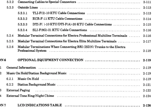
2-1 2-2 2-3 2-4 2-5 2-6 2-7 2-8 2;9 2-10 2-11 2-12 2-13 2-14 2-15 2-16 2-17 2-18 2-19 2-20 2-21 2-22 2-23 2-24 2-25 2-26 2-27 2-28 2-29 2-30 2-31 2-32 2-33 2-34 2-35
LIST OF FIGURES
2-38 2-39 2-40 2-41 2-42 2-43 2-44 2-45 2-46 2-47 2-48 2-49 2-50 2-51 2-52 2-53 2-54 2-55 2-56 2-57 2-58 2-59 2-60 2-61 2-62 2-63 2-64 2-65 2-66 2-67 2-68 2-69 2-70 2-71 2-72
Connecting the CID to the CO1 ... 2-56 DataMessageFormat ... 2-57
-- _\ DID-F(4)-10 KTU Switch Layout ... 2-59 : i \ i .. TLI-F(S)-10 KTU Switch Layout ... : ... 2-60 DTI-F( )-10KTUSwitchLayout ... 2-62 DTI-F(A)-20 KTU Switch Layout (Series 300 or higher) ... 2-62 Connecting the Cable Between the BRT-F(4)-10 KTU and the CLK-F-21 Unit ... 2-67 BRT-F(4)-10 KTU Switch Layout ... 2-68 MountedCLK-F-21Unit ... 2-70 12-Multiframe Configuration and Bit Assignment ... 2-72 2CMuItiframe Configuration and Bit Assignment ... 2-73 Installing the DTI-F( j-10 KTU or DTI-F(A)-20 KTU in the ESF-H-10 KSU ... 2-74 Installing the DTI-F( j-10 KTU or DTI-F(A)-20 KTU in the first two ESF-H-10 KSUs ... 2-75 Connecting the Cable Between the DTI-F( j-10 KTUs or DTI-F(A)-20 KTUs
2-74
Simplified Schematic of Single Line Telephone Connection ... ...2-75
Crossconnection of Single Line Telephones ... ...2-76
Simplified Schematic for BRI Connection ... ...2-77
MOH Cable Shield Ground Exposed ... ...2-78
Music Source Connection ... ...2-79
MOH Cable Route ... ...2-80
Music Source Connection ... ...2-81
Connecting External Paging ... ...2-82
Connecting External Tone Ring/Night Chime ... ......
...
...
...
...
...
...
...
...
...
...
...
...
...
...
...
...
. . . ...
...
...
...
...
...
...
...
...
LIST OF TABLES
2-1
2-2
2-3
2-4
2-5
2-6
2-7
2-8
2-s
2-10
2-11
2-12
2-13
2-14
2-15
2-16
2-17
2-18
2-192-20
2-21
2-22
2-23
2-24
2-25
Abbreviations . . . 2-3 /’ System Control Capacities ...
Multiline Terminal Loop Resistance and Cable Length ... Single Line Telephone Connection Cable Length ... Power Outputs ...
Power Consumption and Dissipation ... FuseReplacement ...
KTU Battery Backup Time ... Weights and Dimensions ... Tone Patterns ...
Multiline Terminal LED Flash Patterns ... DSSBLF LED Indications ...
Telephone and CO Port Number Example ... Number of Required Interface KTUs ... System Configuration Example ... CPU-F( j-20 KTU Adjustments ... Required Equipment for Caller ID ...
DTI-F( l-10 KTU/DTI-F(A)-20 KTU Switch Settings for MB and SW1
. . .
2-4
. . .2-5
. . .2-6
. . .2-7
. . .2-7
. . .2-7
. . .2-11
. . .2-11
. . .2-14
. . .2-15
. . .2-16
. . . 2-19... 2-21 ...
2-22
. . .
2-42
. . .2-58
. . .2-63
2-28 2-29 2-30 2-31 2-32 2-33 2-34 2-35 ‘2-36 2-37 2-38
CHAPTER
2
ELECTRA
PROFESSIONAL
120
HARDWARE
SPECIFICATIONS
AND
INSTALLATION
SECTION 1 SYSTEM SPECIfiCATIONS 1.1 General Information
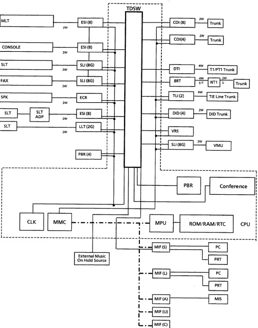
The following diagrams and tables show specifications for the Electra Professional 120 system. The technician should review these carefully before attempting to install the systems.
1.2 System Block Diagram
Februar Y 1998 Electra Professional 12OILevel II/Level II Advanced Installation Service Manual
-II
I
SLI (8G)
I I 11 SPK
i MLT ESI (8)
I I - I
-II
‘1,
i I i
I
I I
-
-
-
-
-
-
-
-
-
-
I
I
I COI (8)
I
I
,c
,c
c
c
2w
DID (4) DIDTrunk I
I
i , , j-1 VRS I
VMU
I i
:
I
MIS
L . mj
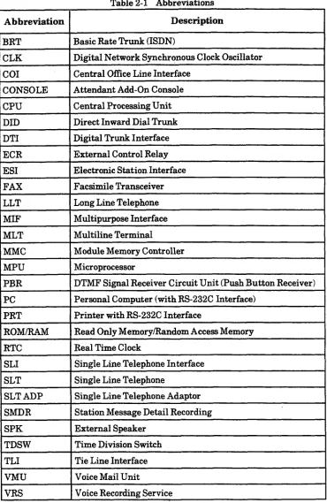
MIF(C) 1I I Table 2-1 Abbreviations I
I
Abbreviation I DescriptionI BRT
I
1 Basic Rate Trunk (ISDN)
CLK Digital Network Synchronous Clock Oscillator co1 Central Office Line Interface
CONSOLE Attendant Add-On Console CPU
DID
Central Processing Unit Direct Inward Dial Trunk DTI
ECR ES1
Digital Trunk Interface External Control Relay Electronic Station Interface FAX
LLT
Facsimile Transceiver Long Line Telephone Multipurpose Interface MLT
MMC
Multiline Terminal
Module Memory Controller MPU
PBR PC
Microprocessor
DTMF Signal Receiver Circuit Unit (Push Button Receiver) Personal Computer (with RS-232C Interface)
PRT ROM/RAM
Printer with RS-232C Interface
Read Only Memory/Random Access Memory RTC
SLI SLT
Real Time Clock
Single Line Telephone Interface Single Line Telephone
SLT ADP SMDR
Single Line Telephone Adaptor Station Message Detail Recording SPK
TDSW
External Speaker Time Division Switch TLI
VMU VRS
Tie Line Interface Voice Mail Unit
Februarv 1998 Electra Professional l%O/Level II/Level II Advanced Installation Service Manual 1.3 System Control Capacities
The control capacities of the system are shown in Table 2-2 - System Control Capacities. Table 2-2 System Control Capacities
120
Item Basic Basic + 2 unit
Expansions
I Interface 5 15
Slot Application Number of Outside Lines
CO/PBX DID E&M Tl
1 2
32 64 NIA
32 64 co1
16 32 DID
8 32 TLI
l(24 l(24 DTI
channels) channels)
ISDN (BasicRate Trunk) 4 8 1 BRT
Yumber of Non-Blocking Intercom Lines I Maximum number of outside lines and
stations that can be simultaneously :onnected (Non-Blocking)
<iline Terminal
4ttendant Add-On Console SLT
40 120 N/A
32 96 ES1
4 4 ES1
24 88 SLI
3LT Adapter
I I I
I 31 I 95
Wm Cordless Terminal 9 9 1 ES1
External Speaker
DTMF Receiver
3 3 ECR
8 8 PBR
Zaller ID 2onference Tenant
1 1 MIF (C)
6 6 CPU
48 48 N/A
1 32 1 32 1 N/ii
Trunk Group
Saute Advance Block System Speed Dial
I 16 16 N/A
Installation Service Manual Electra Professional 12OILevel II/Level II Advanced Februarv 1998 1.4 Cabling Requirements
1.4.1 Cabling Specifications
The KSU is connected with each of the Multiline Terminals and Single Line Telephones by a separate twisted l-pair cable or 2-pair cable (only for Multiline Terminals). Table 2-3 - Multiline Terminal Loop Resistance and Cable Length and Table 2-4 - Single Line Telephone Connection Cable Length show the cables used for wiring between the KSU and individual terminals or adapters.
Table 2-3 Multiline Terminal Loop Resistance and Cable Length
Maximum Terminal or Adapter
Loop Resistance
(Ohms)
I I I
TU-8-f > (BK)/(WH) TEL 35 600 1000
DTU-16-c ) (BK)/(WH) TEL 26 450 900
DTU-16D-( ) (BK)/(WH) TEL 26 450 900
DTU-32-t 1 (BKMWH) TEL 21 360 720
DTU-32D-( 1 (BKY(WH) TEL 21 360 720
DCU-60-t 1 (BK)/(WH) Console 102 1000 10000
ETW-8-t 1 (BKXSW) TEL 61 600 1500
ETW-16DC-( 1 (BKY(SW) TEL 46 450 1300
ETW-16DD-( ) (BK)/(SW) TEL 37 360 820
ETW-24DS-( ) (BKY(SW) TEL 46 450 820
ETW-4R-( 1 (BK) TEL
EDW-48-c ) (BK)/(SW) Attendant Add-On Console with AC Adapter
SLT-F(lG)-10 ADP SLT-F(lG)-20 ADP
N/A 650 650
102 1000 2000
61 600 1200
61 600 1200
Note 1: Note 2: Note 3:
When installing an Attendant Add-On Console, the use of an AC Adapter is required.
The length for the specified SLT Adapter is the length between the ES1 KTU and the SLT Adapter.