Transactions of the 17th International Conference on Structural Mechanics in Reactor Technology (SMiRT 17)
Prague, Czech Republic, August 17 –22, 2003
Paper # J05-5
The Influence of Fluid-structure Interaction on Pipe System Loads
Jarmo Kratz, Wolfgang Münch, Klaus Ungar
TÜV Süddeutschland Bau und Betrieb GmbH, Munich, Germany1
ABSTRACT
Currently two methods are used in structure analysis. In the “uncoupled” method, first a fluid-dynamic analysis is carried out with the assumption of a fixed structure. Next, with the resultant time dependent pressures and reaction forces the structural analysis is made. This method neglects the effects of fluid-structure interaction (FSI). The other method consists of a coupling of both parts, simultaneously calculating the fluid and structure responses under consideration of FSI (“coupled” method).
It should be avoided that in system design, based on the “uncoupled” method, pipe loads are underestimated and potential risks are not identified. As an example to show the influence of the chosen method on the resulting pipe loads we performed calculations for an exemplary NPP pipe system - the emergency core cooling system (ECCS) of a pressurized water reactor (PWR) - assuming different support concepts. Calculations were made without and with consideration of FSI using the fluid-dynamic code DWELL and the structure-dynamic code R2STOSS, both used as stand-alone codes (“uncoupled” method) and as interactive (“coupled”) code system.
Adding to the findings of this analysis the conclusions of other authors it can be recommended that FSI should be taken into account if a strong and rapid excitation takes place in liquid filled, flexibly supported pipe systems consisting of thin-walled, long pipes – especially, if exciting frequency is near to natural frequencies of the system respectively, if system loads are expected to be close to limiting values.
KEY WORDS: fluid-structure interaction, pipe load, support load, pipe rupture, pressure wave, pipe stress, strain, moment, displacement, oscillation, nuclear power plant, dynamic load calculation, fluid-dynamic analysis
INTRODUCTION
Pressure waves in pipe systems of Nuclear Power Plants (NPP) due to pipe rupture or valve operation induce dynamic pipe loads, which have to be evaluated in fluid and structure analyses to show that pipe loading and load transfer to the building do not exceed acceptable limits. The transient reaction of a fluid filled pipe system is determined by the dynamic behaviour of the fluid and the structure as well. The effects caused by the fluid in the structure (elastic axial and radial deformation, axial and torsional motion) themselves affect the fluid pressure and velocity. This phenomenon is called fluid-structure interaction (FSI).
In the literature, e. g. [1] and [2], three coupling mechanisms of FSI are described:
- Junction coupling: This effect is caused by pressure differences between specific points of the pipe system such as bends, tees, changes of cross section, valves or pipe ends. The resultant hydraulic forces induce pipe motions (oscillations in elastic systems) which influence the fluid pressure and velocity (secondary pressure waves). In most cases the junction coupling is dominant compared to the other effects.
- Poisson coupling: Fluid pressure waves cause elastic radial deformations (expansion, contraction) in the pipe wall, which induce an axial stress wave in the wall. This stress wave – propagating along the wall with sonic velocity - produces a secondary fluid pressure wave (precursor wave), which – as the sonic velocity in the wall material is greater than in the fluid - moves ahead of the primary fluid pressure front. In addition the stress wave causes axial motions of the affected pipe.
- Friction coupling: This effect accounts for the mutual friction between fluid and wall. For technical smooth wall surfaces as in NPP pipe systems friction coupling is of minor importance compared to the other coupling mechanisms.
The dynamic load analysis comprises a dynamic and a structure-dynamic part. While the fluid-dynamic analysis provides information on parameters like fluid pressure, velocity and reaction forces, the structure-dynamic analysis gives evidence on pipe stresses, strains, moments, displacements and oscillations.
Currently two methods are used in fluid-structure analysis:
1
1) In the “uncoupled” method, first a fluid-dynamic analysis is carried out with the assumption of a fixed structure. Next, with the resultant time dependent pressures and reaction forces the structural analysis is made. This method neglects the effects of FSI.
2) The other method consists of a coupling of both parts, simultaneously calculating the fluid and structure responses under consideration of FSI (“coupled” method).
To choose the appropriate calculation method one should know about the influence FSI could have on the results. Though it is commonly assumed that the “uncoupled” method is conservative in respect to pipe loads, investigations have shown that the problem is quite complex. The magnitude of the influence of FSI depends on the system characteristics and the initiating event. Therefore, it is difficult to make general statements on the influence of FSI. However, it should be avoided that in system design, based on the “uncoupled” method, pipe loads are underestimated and potential risks are not identified. Therefore the investigations presented in this paper direct attention to the question, if it is possible that neglecting FSI results in lower calculated pipe loads compared to “real” pipe loads (non-conservative results).
SIGNIFICANCE OF FSI FOR SYSTEM LOAD EVALUATIONS
There have been published a lot of studies on FSI in the last twenty years. Exemplarily the investigations concerning the Delft test facility [3], [4], [5], [6] and the excellent survey on the subject in [1] should be mentioned here. The investigations show that the effect of FSI on system loads is dependent on the load case (initiating event) and the system characteristics, e. g.:
- the magnitude of the transient excitation (gradient and magnitude of the pressure change) - the ratio of fluid and structure material properties (densities, modulus of elasticity) - the piping dimensions and arrangement (pipe length/diameter, wall thickness, bends etc.) - the support concept
- the oscillation behaviour (natural frequencies).
Summarizing the findings of various authors, the following items can be specified concerning the significance of FSI for system loads evaluation:
- FSI is of importance only in pipe systems containing liquids, for gases the effect of FSI can be neglected.
- It is assumed that FSI has a substantial effect in “flexible” systems, whereas in more “rigid” systems this effect is rather small.
- FSI affects the oscillation behaviour of pipe systems. If FSI is considered in the analyses both the exciting and the natural frequencies will change in comparison to uncoupled analyses. If there is a risk that system natural frequencies could be excited by the pressure wave FSI should be taken into account (resonance).
- In most cases analyses of pipe systems typical for power plants resulted in decreased structure loads if FSI was considered.
- Nevertheless, studies at experimental facilities (e. g. Delft experiment [4]) systematically varying the system rigidity gave evidence for contrary effects of FSI on the different quantities (pressures, displacements, stresses, moments). Moreover, in more flexible systems the stresses will be underestimated if FSI is neglected.
Although the literature study gives a complex and graduated picture on how FSI can influence pipe loads there are only sparse indications of situations, when neglecting FSI could result in an underestimation of loads. So, in case of doubt it is advisable to carry out system specific analyses to clarify the problem.
CALCULATIONS OF SYSTEM LOADS IN AN EMERGENCY CORE COOLING SYSTEM
Description of the Pipe System
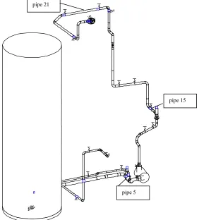
Fig. 1 shows the system investigated in this study. It is a part of one leg of the high pressure injection system of a PWR, connecting the borated water storage tank with the reactor coolant line. It includes the high pressure injection pump and the check valves, the closure of which induces the pressure wave.
pipe 21
pipe 5
pipe 15
Figure 1: Overall view of the high pressure injection system
The Fluid-Dynamic Code DWELL and the Structure-Dynamic Code R2STOSS
For the calculation of the fluid-dynamic quantities we used the code DWELL developed by TÜV Süddeutschland [8]. DWELL solves the equations of conservation of mass (Eq. (1)) and momentum (Eq. (2)) with the method of characteristics (MOC). Energy conservation is approximated by an equation of state (Eq. (3)). The extended form of the mass and momentum equation accounts for FSI. Radial deformation of the pipe is considered by the factor in the equation of conservation of mass Eq. (1). The term is calculated using the boiler formula (see Eq. (4)). The dependence of the sonic velocity on pressure resp. density is considered, too. The last term on the right side of the momentum equation (Eq. (2)) is the axial acceleration of the pipe relatively to the fluid. This term describes the junction coupling.
1
ε
k kε1
x w x w k
t ∂
ρ ∂ ∂ ∂ ρ ∂
ρ ∂
ε −
−
= 1 (1)
(2)
axial q g
w w d x c x w w t w
&& − −
− −
−
= λ α
∂ ρ ∂ ρ ∂ ∂ ∂
∂
sin 2
2
(3) )
(ρ
p p=
2 1
) 1 ( 1
1
c d
k
ν δ ρ
ε
− +
The structural analysis was made with the code R2STOSS [9]. The equations of motion (Eq. (5)) are solved by direct integration based on the Newmark method.
[ ]
M ⋅{ }
q&& +[ ]
D ⋅{ }
q& +[ ]
K ⋅{ }
q ={ }
F( )
t (5)As a result of the integration one gets the time dependent deformation vector
{ }
q , the pipe velocities and accelerations . The stresses in the pipe elements can be calculated from the deformations (displacements and torsions) as well as the forces on attachments and supports (support loads).{ }
q&{ }
q&&In case of an “uncoupled” analysis the fluid and the structural calculations are carried out separately. The time dependent function of reaction forces, calculated in a preceding DWELL run, are given to R2STOSS as external forces. In a “coupled” analysis both codes run simultaneously on a PC. At each time step the results are transferred from DWELL to R2STOSS and vice versa via a special interface. By this method all fluid and structural quantities were calculated during one run. The reaction forces calculated by DWELL act as external forces on the structure model of R2STOSS and in the other direction the pipe motion acts back on the fluid. In this way FSI is considered.
Calculation Model
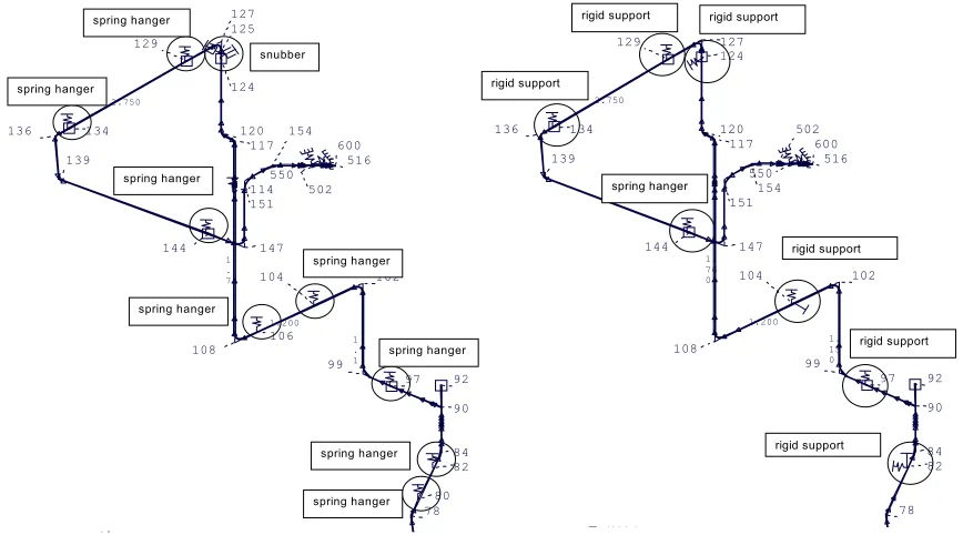
Nowadays there is a tendency towards optimised support structures of pipe systems, as far as possible eliminating spring hangers and snubbers that are subject to costly maintenance. Fig. 2 shows the two support concepts investigated for the high pressure injection system (see Fig. 1). The main elements of the old support concept (Fig. 2, left) are spring hangers, that carry the pipe weight, and allow for motion in all directions. Additional, there are snubbers at some positions designated to absorb shock impacts. In the new, optimised support concept (Fig. 2, right) snubbers were completely eliminated. Instead, to compensate their function at some places spring hangers were replaced by more rigid supports. Fixed points are the same in both the new and the old concept, being located at the tank, the pump and the containment wall. Whereas the fluid-dynamic calculations were made with one calculation model for both support concepts for the structure analysis two calculation models were used. The modelled section is restricted to the part between the tank and the containment, which are fixed points. The two models only differ in the number, type and location of the supports. 1 . 1 1 . 2 1 . 1 1.200 1 . 7 2.750 2.786 A121 A122 A14 78 80 82 84 90 97 99 102 104 106 108 114 117 120 124 125 127 129 134 136 139 144 147 151 154 502 516 600 92 550 spring hanger spring hanger spring hanger snubber spring hanger spring hanger spring hanger spring hanger spring hanger
Figure 2: Old (left hand side) and optimised (right hand side) pipe support concept (detail)
Initial And Boundary Conditions
The transient is initiated by the failure of the high pressure injection pump at 0.5 s. When the fluid flow changes its direction the check valve starts to close. The closing time is assumed to be 0.35 s. The pressure in the
1. 18 1. 27 6 1. 15 0 1.200 1. 76 0 2.750 2.786 A121 A122 A14 78 82 84 90 97 99 102 104 108 117 120 124 127 129 134 136 139 144 147 151154 502 516 600 92 550 rigid support rigid support spring hanger rigid support
rigid support rigid support
water storage tank is 0,15 MPa and in the reactor vessel 8 MPa. The volumetric flow through the pump is approximately 0,044 m3/s at a delivery pressure of 8 MPa.
Discussion of the Results
For the pipe system described above we performed calculations for the old and the optimised support concept with and without consideration of FSI. We compared the maximum values of the fluid pressures, the reaction forces, the pipe stress intensities and support loads for all fluid and pipe sections. The comparison showed that for the specific conditions (system configuration, support concepts, load case) the “uncoupled” analyses gave in all cases – both for the old and the optimised support concept - higher maximum values for pressure, stress and support loads compared to those from the “coupled” analyses. The differences between “uncoupled” and “coupled” results vary – depending on the position in the pipe system – from a few percent up to almost 100 percent. For a position downstream the closing valve (pipe 15, see fig. 1) the results for pressures and stresses are shown in figures 3 and 4.
1.3 1.4 1.5 1.6 1.7 1.8 1.9 2
time [s] 7.00e+006
7.20e+006 7.40e+006 7.60e+006
new support concept, coupled old support concept, coupled uncoupled
pressure [Pa]
Figure 3: Comparison of pressures in pipe 15 with and without consideration of FSI for the old and the optimised (new) support concept
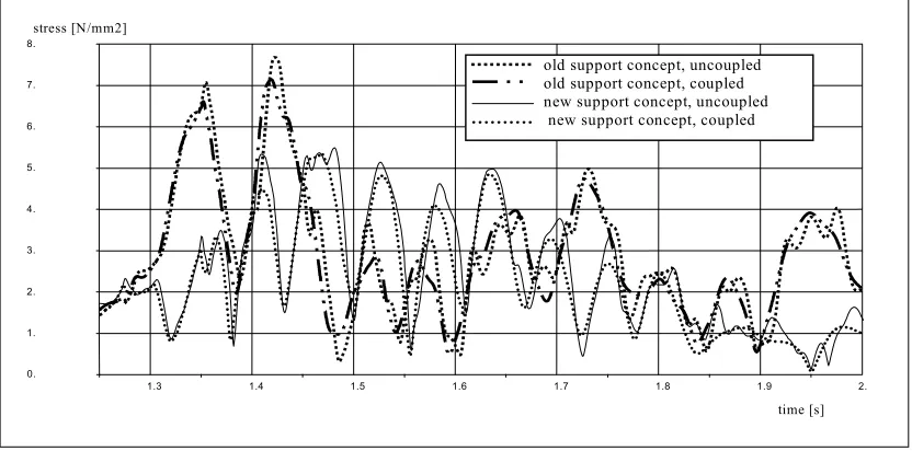
1.3 1.4 1.5 1.6 1.7 1.8 1.9 2.
time [s]
0. 1. 2. 3. 4. 5. 6. 7. 8.
stress [N/mm2]
old support concept, uncoupled old support concept, coupled new support concept, uncoupled new support concept, coupled
Figure 4: Comparison of stresses in pipe 15 with and without consideration of FSI for the old and the optimised (new) support concept
the more rigid system (see fig. 4), but there are positions showing the opposite (see figure 5). The magnitude of pipe loads depend on the specific pipe configuration and kind and function of support in the pipe section under consideration and has to be checked for each pipe section. So, one should be carefully in drawing conclusions regarding pipe loads from “global” system flexibility.
1.3 1.4 1.5 1.6 1.7 1.8 1.9 2.
time [s]
0. 1. 2. 3. 4. 5. 6. 7. 8. 9. 10. 11.
stress [N/mm2]
old support concept, coupled new support concept, coupled
Figure 5: Comparison of stresses in pipe 21 with consideration of FSI for the old and the optimised (new)
support concept
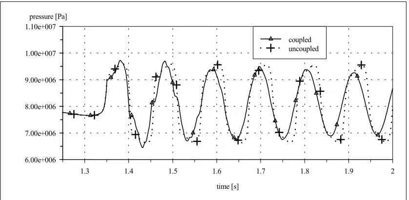
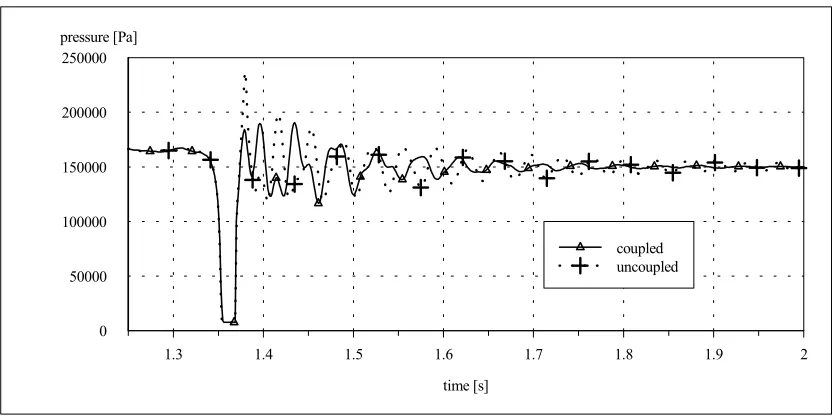
Regarding the question if “uncoupled” calculations could result in non-conservative loads the above described calculations can not give a definite answer because besides the analysed pipe system flexibility there are a lot of parameters and parameter combinations that could influence the system behaviour. One of them is the initiating pressure transient. For this reason we made additional calculations with an enforced initial excitation by arbitrarily closing the valve at higher fluid velocities. The results of these calculations are shown in figures 6-8. From the pressure plot (fig. 6) it can be seen that the “coupled” calculation results in a higher pressure wave frequency and pressure peaks that exceed those of the “uncoupled” calculation. For another position (pipe 5, upstream of the closing valve, see fig. 1) we found a pipe section, where the stresses are higher when calculated with the “coupled” method (see fig. 8). Obviously this is due to resonance effects.
1.3 1.4 1.5 1.6 1.7 1.8 1.9 2
time [s] 6.00e+006
7.00e+006 8.00e+006 9.00e+006 1.00e+007 1.10e+007
coupled uncoupled pressure [Pa]
1.3 1.4 1.5 1.6 1.7 1.8 1.9 2
time [s] 0
50000 100000 150000 200000 250000
coupled uncoupled pressure [Pa]
Figure 7: Comparison of fluid pressures in pipe 5 with and without consideration of FSI, strong excitation
1.3 1.4 1.5 1.6 1.7 1.8 1.9 2.
time [s]
0. 1. 2. 3. 4. 5. 6. 7. 8. 9. 10. 11. 12.
stress [N/mm2]
coupled uncoupled
Figure 8: Comparison of stresses in pipe 5 with and without consideration of FSI, strong excitation
CONCLUSIONS
Because of the complexity of the interacting effects and the great number of different existing pipe system configurations - including different support concepts - it is not possible to make general statements on the influence of FSI on system loads. Nevertheless, based on a literature study and on own calculations we will try to give some guidance on how to handle the problem in system analysis practice:
For the defined load case system specific analyses should be made. If possible, coupled methods should be applied, because considering FSI results in pipe loads, that are closer to “real” loads than those without FSI. Precondition is that the FSI methods used have been validated by comparison with experimental results. If “uncoupled” methods are used, the results should be carefully evaluated regarding their “conservativity”. Under certain circumstances, especially if
- the calculations show that system loads are near the limiting values
- a frequency analysis shows, that the exciting frequency is near natural system frequencies it can be useful to check them by results of a coupled analysis.
For load cases
- initiated by rapid pressure transients in pipe systems
- consisting of long, thin-walled pipes (small wall thickness) - flexibly supported
coupled analysis should be preferred.
Meanwhile tested coupled computer programs are available to most of the institutions involved in such analyses. So, in the authors opinion, in fluid-structure analysis the step toward coupled methods should be made in general. This would contribute to minimise the potential of inadequate system design, both by under- and overestimation of pipe loads.
NOMENCLATURE
c fluid sonic velocity d internal pipe diameter E modulus of elasticity g gravitational constant
p fluid pressure
&&
qaxial axial acceleration of a pipe element
t time
w fluid velocity
x distance along pipe axis
α angle of inclination
δ pipe wall thickness
λ wall friction coefficient
ν Poisson´s ratio
ρ fluid density
REFERENCES
1. A. S. Tijsseling, “Fluid-structure interaction in liquid-filled pipe systems: A review”, Journal of Fluids and Structures (1996) 10, pp. 109-146
2. Z.M. Wang, S.K. Tan, “Coupled analysis of fluid transients and structural dynamic responses of a pipeline system”, J. Hydraul. Res., 1997, 35(1), pp. 119-131
3. A.G.T.J. Heinsbroek, “Fluid-structure interaction in non-rigid pipeline systems - comparitive analyses”,
ASME/TWI 12th Int. Conf. on Offshore Mechanics and Arctic Engineering, Glasgow, Scotland, UK,
June 1993, Paper OMAE-93-1018, pp. 405-410
4 A.G.T.J. Heinsbroek, A.S. Tijsseling, “The influence of support rigidity on waterhammer pressures and pipe stresses”, 2nd Conf. on Water Pipeline Systems, Edinburgh, Scotland, 1994 BHR Group Ltd.
5 A.G.T.J. Heinsbroek, “Fluid-structure interaction in non-rigid pipeline systems”, Nucl. Engng. Des., 1997,172(1/2):123-135
6 A.S Tijsseling, A.G.T.J.Heinsbroek, “The Influence of Bend Motion on Water Hammer Pressures and Pipe Stresses”, Proceedings of ASME/JSME FEDSM'99, 1999 ASME/JSME Fluids Engineering Division Summer Meeting, San Francisco, Cal., July 18-23, 1999, FEDSM99-6907
7. J. Kratz, W. Münch, „Verbesserung der Bewertung bei hydrodynamischen Belastungen druckführender Komponenten bei Störfällen in Leichtwasserreaktoranlagen“, Abschlussbericht, TÜV-BB/ETR 1, München, 18.09.2002
8. J. Kratz, „Fluiddynamikprogramm DWELL/DWELL-S“, Programmbeschreibung, TÜV-BB/EKA-3, München, 09.07.1999