ABSTRACT
LIM, HO SUN. Three Dimensional Virtual Try-on Technologies in the Achievement and Testing of Fit for Mass Customization. (Under the direction of Dr. Cynthia L. Istook and Dr. Trevor J. Little).
Consumers using on-line shopping have increased dramatically and Internet shopping has rapidly grown as a compelling channel for sale of garment products. However, it has the problem that garments don’t exactly fit on consumers’ bodies and high product return rates persist because consumers can’t try on garments before purchasing. Therefore, apparel companies currently focus more on providing mass customization and three-dimensional virtual try-on for consumers who shop online. Online apparel shopping currently provides virtual avatars created by manual method, but the avatars aren’t the same as consumers’ bodies. To overcome this disadvantage, the study for virtual avatars directly imported from 3D body scanners is required in the future market.
The purpose of this research is to evaluate the fit and appearance of virtual try-on garments and develop an exchange between a database of three-dimensional body scanning systems and virtual try-on software.
were developed using the Gerber AccuMark PDS system. The 3D virtual garments made from the imported 2D patterns were then tried on the 3D direct and manual virtual avatars. Finally, the fit of the real garments and the virtual garments was compared using a survey instrument.
Comparing the virtual avatars, the direct avatar (Avatar 1) was the most similar to the real body, while the manual avatars (Avatar 2 and 3) were different from the real body. The manual avatars of Oval, Spoon, and Rectangle shapes were very different from the real body and direct avatars may be required to be used for these somatotypes. This study found the similarity of the virtual garments was related to the similarity of the virtual avatars. The real garments with the real body and the virtual garment with the direct avatar were preferred by most respondents. Also, the older subjects reported they less satisfied with the size/fit of ready-to-wear clothing. Therefore, the virtual avatars for the middle aged females are required for the garment fit in the apparel industry.
Three Dimensional Virtual Try-on Technologies in the Achievement and Testing of Fit for Mass Customization
by Ho Sun Lim
A dissertation submitted to the Graduate Faculty of North Carolina State University
in partial fulfillment of the requirements for the Degree of
Doctor of Philosophy
Textile Technology and Management
Raleigh, North Carolina
2009
APPROVED BY:
______________________ _____________________
Dr. Cynthia Istook Dr. Trevor J. Little Committee Chair Co-Chair
______________________ _____________________
DEDICATION
This dissertation is dedicated to God to my Jesus Christ,
to my parents, Myeongok Lim and Jeongsuk Eun to my husband, Jeongha Hwang
BIOGRAPHY
Hosun Lim, daughter of Myeongok Lim and Jeongsuk Eun, was born December 25, 1973, in Seoul, South Korea.
She graduated from Sookmyung Women‟s University in Seoul, South Korea in 1996. She studied fashion design and pattern making at Istituto Carlo Secoli, Milan, Italy (1996-1998). She took women‟s pattern, men‟s pattern, women‟s underwear pattern, apparel CAD, and fashion design courses from Istituto Carlo Secoli. She received diplomas including pattern maker and pattern CAD maker. In February 2003, she graduated with a Master in Clothing and Textiles from Yonsei University.
After graduation, she worked as research assistant for Korea Institute of Industrial Technology (KITECH), Cheonan, South Korea (2003-2004). She taught the pattern making courses at Seedae Fashion Design Academy, Seoul, South Korea (2004-2005). In 2004, she was married to Jeongha Hwang.
ACKNOWLEDGEMENTS
I wish to express my sincere gratitude to Dr. Cynthia, L. Istook, chair of my advisory committee. She always has encouraged me and has support my research. I would like to express my sincere appreciation to Dr. Trevor J. Little, co-chair of my co-advisory committee, for supporting me to complete this program. I would also like to express my thanks to my advisory committee members Dr. Michelle R. Jones, and Dr. Jeffrey R. Thompson for their support and recommendations.
I would like to express my thanks to Dr. Moon W. Suh, Dr. Nancy L. Cassill, Dr. Pam Banks-Lee, Dr. Stephen Michielsen, Dr. Helmut H. Hergeth, Dr. George L. Hodge, Dr. Traci May Lamar, and Professor Nancy Boiter Powell for their advices.
Many thanks to David Bruner, Susan Simon, Dave Woronka, and Elizabeth White in [TC]², Matt Bakhoum, Josh Scott, and Julia Shaw in OptiTex, and Hamutal Menashe, Sigal Reif, and Udi Avivi in Brozwear.
TABLE OF CONTENTS
LIST OF TABLES ... viii
LIST OF FIGURES ... ix
1. INTRODUCTION... 1
1.1. Research Objectives ... 2
1.2. Study Limitations ... 3
2. LITERATURE REVIEW ... 4
2.1. Mass Customization ... 4
2.1.1. Apparel Mass Customization ... 8
2.1.2. Apparel Companies for Mass Customization ... 14
2.1.2.1. Levi Strauss & Co. ... 15
2.1.2.2. Brooks Brothers Inc. ... 16
2.1.2.3. Interactive Custom Clothes Company (IC3D) ... 17
2.2. Advanced Mass Customization in Apparel ... 19
2.2.1. 3D Body Scanning Technology and Fit ... 19
2.2.1.1. Telmat Industrie ... 21
2.2.1.2. [TC]² ... 24
2.2.1.3. Wicks and Wilson, Limited ... 26
2.2.1.4. Cyberware ... 28
2.2.1.5. Human Solutions (TecMath) ... 31
2.2.2. Virtual Try-On ... 34
2.2.2.1. Virtual Try-On Overview ... 35
2.2.2.2. Virtual Try-On Technologies ... 38
2.2.2.3. Virtual Try-On Apparel Websites ... 48
2.3. Summary of Literature ... 51
3. METHODOLOGY ... 52
3.1.1. Initial Sample Collection ... 54
3.1.2. Body Measurement ... 54
3.1.3. Final Sample Selection ... 55
3.1.4. Three-dimensional Avatar from [TC]2 Body Scan Data ... 56
3.2. Generating Avatars (Objective Two) ... 57
3.2.1. Direct 3D avatar from [TC]2 body scan data ... 57
3.2.2. Manual 3D avatar from body measurement... 57
3.3. Generating Garment patterns (Objective Three) ... 60
3.3.1. Selection of Garment Design ... 60
3.3.2. Basic Patterns ... 61
3.3.2. Alteration Rule of Garment Patterns ... 62
3.4. Virtual Try-on (Objective Four) ... 62
3.4.1. Real Garment ... 63
3.4.1.1. Measurement of Fabric Properties ... 63
3.4.1.2. Real Garment Production ... 70
3.4.2. Virtual Garment ... 70
3.4.3. Comparing the Fit of a Virtual Garment with a Real Garment ... 71
4. RESULTS ... 72
4.1. Results in Body Scan Data (Objective One) ... 72
4.1.1. Subjects‟ Size Knowledge ... 73
4.1.2. Subjects‟ Body Shapes ... 77
4.1.2.1. Female Body Shape Category ... 77
4.1.2.2. Top Five Body Shapes ... 78
4.1.3. [TC]2 Body Model ... 83
4.1.3.1. Point Cloud Data (PCD) ... 84
4.1.3.2. Vrml File Data ... 85
4.1.3.3. Morph Avatar Model ... 86
4.1.4. Virtual Avatar using direct transfer from [TC]2 Body Scan Data ... 90
4.2.1. Virtual avatar using manual input from body measurement ... 92
4.2.1.1. OptiTex software system ... 92
4.2.1.2. V-stitcher software system ... 107
4.2.1.3. Direct and Manual Avatars ... 116
4.3. Results in Generating Garment patterns (Objective Three) ... 128
4.3.1. Basic Block Patterns ... 128
4.3.2. Made-to-Measure (MTM) Patterns ... 132
4.3.2.1. Critical Alteration Points ... 132
4.3.2.2. Alteration Point Numbers ... 132
4.3.2.3. Grade Rules ... 134
4.3.2.4. Alteration Rules ... 136
4.3.2.5. Size Rules... 144
4.3.2.6. Individual Patterns ... 146
4.4. Results in Virtual Try-on (Objective Four) ... 148
4.4.1. Real Garments ... 148
4.4.1.1. Fabric Properties ... 148
4.4.1.2. Real Garments for Final Subjects ... 153
4.4.2. Virtual Garments ... 154
4.4.2.1. OptiTex ... 154
4.4.2.2. V-stitcher ... 160
4.4.3. Real and Virtual Garments ... 166
4.4.3. Fit Evaluation of Virtual Garments with Real Garments ... 174
4.4.3.1. Survey Development ... 174
5. CONCLUSION AND RECOMMENDATIONS ... 195
5.1. Conclusions ... 195
5.2. Recommendations ... 202
REFERENCES ... 204
APPENDIX A ... 214
LIST OF TABLES
Table 1. Three-dimensional scanning systems ... 21
Table 2. Measure names between OptiTex and [TC]2 ... 58
Table 3. Measure names between V-stitch and [TC]2 ... 59
Table 4. Fabric Properties Measured on the FAST System ... 64
Table 5. Comparing the body image with three virtual avatars for Hourglass ... 118
Table 6. Comparing the body image with three virtual avatars for Bottom Hourglass ... 120
Table 7. Comparing the body image with three virtual avatars for Oval ... 123
Table 8. Comparing the body image with three virtual avatars for Rectangle ... 125
Table 9. Comparing the body image with three virtual avatars for Spoon ... 127
Table 10. Standard table of body measurements for adult female misses figure type ... 129
Table 11. Alteration point numbers ... 133
Table 12. FAST Test Results of Sample Test Fabrics ... 149
LIST OF FIGURES
Figure 1. Structure of In-Store Service for Mass Customization (Lee & Chen, 1999) ... 10
Figure 2. Consumer Driven Model (Anderson-Connell et al., 2002) ... 13
Figure 3. IC3D Customer Eleven Measurements (IC3D, 2008) ... 18
Figure 4. IC3D Customer Design Process ... 18
Figure 5. Telmat Industrie‟s 3D SYMCAD OptiFit system (Hamit, 2001) ... 22
Figure 6. Shadow grid lines seen in SYMCAD (Telmat, 2008) ... 22
Figure 7. SYMCAD Body Card information based on ISO 8559 (Hwang, 2004) ... 23
Figure 8. Automatic detection of anatomical landmarks (Telmat, 2008) ... 24
Figure 9. [TC]²‟s triangulation between projector camera and subject ([TC]², 2008) ... 25
Figure 10. 3D point cloud data ([TC]², 2008) ... 26
Figure 11. Segmentation of the body ([TC]², 2008) ... 26
Figure 12. Printout available to subject ([TC]², 2008) ... 26
Figure 13. Triform from Wicks & Wilson (Wicks & Wilson Limited, 2008) ... 27
Figure 14. Triform‟s moiré fringe technique (Wicks & Wilson Limited, 2008) ... 28
Figure 15. Model WBX; Cyberware‟s body X 3D body scanner (Cyberware, 2008) ... 29
Figure 16. Model WB4; Cyberware‟s body color (Cyberware, 2008) ... 30
Figure 17. VRML image with extracted measurements (Cyberware, 2008) ... 31
Figure 18. ANTHROSCAN system of Human Solutions (Human Solutions, 2008) ... 33
Figure 19. Landmarks of the ANTHROSCAN system (Human Solutions, 2008) ... 33
Figure 20. Virtual Try-on overview (Martin Rupp, 2004)... 34
Figure 21. The key issues of interactive 3D CAD system (Hardaker & Fozzard, 1998) ... 35
Figure 22. Browzwear (Hwang, 2004) ... 40
Figure 23. OptiTex software (OptiTex, 2008) ... 42
Figure 24. A tension map generated by OptiTex software (OptiTex, 2008) ... 43
Figure 25. A tension map of Lectra Systems (Lectra Systems, 2008) ... 44
Figure 27. Accumark APDS-3D (Hwang, 2004) ... 45
Figure 28. Accumark V-Stitcher of Gerber (Gerber Technology, 2008) ... 46
Figure 29. TUKATECH‟s e-fit Simulator (Delevan, 2007) ... 47
Figure 30. My Virtual Model of Landsend.com ... 48
Figure 31. Virtual Model of MVM ... 50
Figure 32. MyVirtualModel system (MyVirtualModel, 2008) ... 50
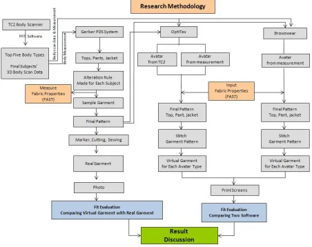
Figure 33. Research Methodology ... 53
Figure 34. Scan data processing for 3D avatar ... 56
Figure 35. Front and back views of tank top, pants, and jacket ... 61
Figure 36. Fit Evaluation Process of Real and Virtual Garment ... 63
Figure 37. FAST-1 Compression meter ... 66
Figure 38. Schematic diagram of FAST-1 ... 66
Figure 39. FAST-2 Bending meter ... 66
Figure 40. Schematic diagram of FAST-2 ... 66
Figure 41. FAST-3 Extension meter ... 67
Figure 42. Schematic diagram of FAST-3 ... 67
Figure 43. Schematic diagram of FAST-4 dimensional stability test ... 68
Figure 44. Example of FAST chart ... 69
Figure 45. Process of Virtual Garment Simulation ... 71
Figure 46 . Age frequencies for the 61 respondents ... 73
Figure 47 . Race/ Ethnicity frequencies for the 61 respondents ... 74
Figure 48. Size knowledge of respondents ... 75
Figure 49 . Comparison the scaned sizes with the answered sizes ... 76
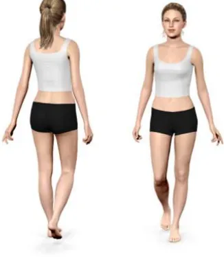
Figure 50. Female body shapes ... 78
Figure 51 . Final subject of Hourglass shape ... 79
Figure 52 . Final subject of Bottom Hourglass shape ... 80
Figure 53. Difference of Bottom Hourglass (green) and Hourglass (blue) ... 80
Figure 54 . Final subject of Rectangle shape ... 81
Figure 56. Final subject of Oval shape ... 82
Figure 57. Difference of Oval (green) and Hourglass (blue) ... 82
Figure 58. Final subject of Spoon shape ... 83
Figure 59. Difference of Spoon (green) and Hourglass (blue) ... 83
Figure 60. Body Model for Point cloud data (*.rbd) ... 84
Figure 61. Body Model for Vrml format file (*.wrl) ... 85
Figure 62. Batch Process Dialog ... 86
Figure 63. Morph model tool ... 87
Figure 64. Morph avatar model ... 88
Figure 65. 3D Points of the VRML file ... 88
Figure 66. 3D points of morphed avatar ... 89
Figure 67. Morph avatars of top five body shapes ... 89
Figure 68. 3D virtual avatar imported from morph model file ... 90
Figure 69 . Direct 3D avatars of five final subjects from [TC]2 body scan data ... 91
Figure 70. Measurements of Eva ORD file ... 94
Figure 71. The model properties window of OptiTex software ... 95
Figure 72. „OptiTex_Modulate_and_Model‟ MEP file ... 96
Figure 73. „Hip‟ measurement with parameters ... 97
Figure 74. MEP file and ORD file of Hourglass ... 98
Figure 75. MEP file and ORD file of Bottom Hourglass ... 99
Figure 76. MEP file and ORD file of Oval ... 100
Figure 77. MEP file and ORD file of Rectangle ... 101
Figure 78. MEP file and ORD file of Spoon ... 102
Figure 79. Manual 3D avatar (Avatar 2) of Hourglass ... 104
Figure 80. Manual 3D avatar (Avatar 2) of Bottom Hourglass ... 105
Figure 81. Manual 3D avatar (Avatar 2) of Oval ... 106
Figure 82. Manual 3D avatar (Avatar 2) of Rectangle ... 106
Figure 83. Manual 3D avatar (Avatar 2) of Spoon ... 107
Figure 85. MEP file and ORD file of Hourglass ... 109
Figure 86. Manual 3D avatar (Avatar 3) of Hourglass ... 111
Figure 87. Manual 3D avatar (Avatar 3) of Bottom Hourglass ... 112
Figure 88. Manual 3D avatar (Avatar 3) of Oval ... 113
Figure 89. Manual 3D avatar (Avatar 3) of Rectangle ... 114
Figure 90. Manual 3D avatar (Avatar 3) of Spoon ... 115
Figure 91. Direct and manual avatars of Hourglass ... 118
Figure 92. Direct and manual avatars of Bottom Hourglass ... 120
Figure 93. Direct and manual avatars of Oval ... 122
Figure 94. Direct and manual avatars of Rectangle ... 124
Figure 95. Direct and manual avatars of Spoon ... 126
Figure 96. Basic pattern of tank top ... 130
Figure 97. Basic pattern of pants ... 130
Figure 98. Basic pattern of jacket ... 131
Figure 99. Alteration point numbered in the pattern piece ... 133
Figure 100. Grade rule table with missy size ... 134
Figure 101. Grade point numbers of tank top ... 135
Figure 102. Graded nest of tank top ... 135
Figure 103. Grade point numbers of pants ... 135
Figure 104. Graded nest of pants ... 135
Figure 105. Grade point numbers of jacket ... 136
Figure 106. Graded nest of jacket ... 136
Figure 107 Alteration point numbers of tank top ... 138
Figure 108 Alteration table of tank top ... 139
Figure 109. Alteration point numbers of pants ... 140
Figure 110. Alteration table of pants ... 141
Figure 111. Alteration point numbers of jacket ... 143
Figure 112. Alteration table of jacket ... 143
Figure 114. Size table of pant ... 145
Figure 115. Size table of jacket ... 145
Figure 116. Altered size (AM) ... 146
Figure 117. Altered pattern of tank top (Hourglass) ... 147
Figure 118. Altered pattern of pant (Hourglass) ... 147
Figure 119. Altered pattern of jacket (Hourglass) ... 147
Figure 120. Sample fabrics (Left: Brown gabardine, Right: Yellow silk charmeuse) ... 149
Figure 121. FAST control chart of gabardine fabric (101A) ... 151
Figure 122. FAST control chart of yellow charmeuse (102A) ... 153
Figure 123. FAST chart and OptiTex fabric converter for brown gabardine ... 155
Figure 124. OptiTex fabric converter for yellow silk ... 156
Figure 125. Virtual stitch for tank top (OptiTex software) ... 157
Figure 126. Virtual stitch for pants (left) and jacket (right) (OptiTex software) ... 157
Figure 127. „Simulate draping‟ for tank top (OptiTex software) ... 158
Figure 128. „Simulate draping‟ for pants (OptiTex software) ... 159
Figure 129. „Simulate draping‟ for jacket (OptiTex software) ... 159
Figure 130. V-stitcher fabric properties for yellow silk ... 161
Figure 131. V-stitcher fabric properties for brown gabardine ... 162
Figure 132. Virtual stitch for tank top (V-stitcher software) ... 163
Figure 133. Virtual stitch for pants (V-stitcher software) ... 163
Figure 134. Virtual stitch for jacket (V-stitcher software) ... 164
Figure 135. „Simulation‟ for tank top (V-stitcher software) ... 165
Figure 136. „Simulation‟ for pants (V-stitcher software) ... 165
Figure 137. „Simulation‟ for jacket (V-stitcher software) ... 166
Figure 138. Real and virtual tank tops for five body shapes ... 169
Figure 139. Real and virtual pants for five body shapes ... 172
Figure 140. Real and virtual jackets for five body shapes ... 173
Figure 141. Gender ... 176
Figure 143. Race ... 177
Figure 144. Occupation ... 177
Figure 145. Education ... 178
Figure 146. Income ... 178
Figure 147. Preferred shopping place ... 179
Figure 148. Fit satisfaction ... 180
Figure 149. Frequency online shopping ... 181
Figure 150. Likely to shop online ... 181
Figure 151. My Virtual Model ... 182
Figure 152. Similar body ... 183
Figure 153. Percentage of “YES”; Purchase decision of Rectangle ... 186
Figure 154. Percentage of “YES”; Purchase decision of Hourglass ... 187
Figure 155. Percentage of “YES”; Purchase decision of Bottom Hourglass ... 188
Figure 156. Percentage of “YES”; Purchase decision of Oval ... 189
Figure 157. Percentage of “YES”; Purchase decision of Spoon ... 190
Figure 158. Percentage of “YES”; Purchase decision of total five body shapes ... 191
1. INTRODUCTION
The apparel industry is undergoing rapid evolutionary changes that have resulted from the digital revolution, globalization, and consumer demands. Previously, a lack of product availability required consumers to tolerate products that did not meet their expectations. However, this has changed and consumers desire to personalize the style, fit and color of the clothes they choose. Given the changing characteristics of consumer interests, mass production systems cannot satisfy both manufacturers and consumers (Smith-Outling, 2007). One resource that fulfils the consumers‟ and manufacturers‟ need for personalization and a low-cost customized product is mass customization (Rosneau & Wilson, 2006). To survive in the apparel market a company must acquire the consumers‟ attention to purchase its product through customization programs which can produce personalized products. Therefore, many companies have changed from mass production to mass customization and they are actually operating at various levels of mass customization (Yunchu, & Weiyuan, 2007).
to purchase garments online or are unsatisfied with their online shopping experience because they perceive risk to exist due to their inability to try on garments (Horrigan, 2008). Therefore, computer aided design systems companies have developed Virtual-try-on visualization techniques for the apparel industry, enabling visualization of garments on three dimensional avatars. Virtual try-on is defined as the computer simulation that enables customers to choose their 3D avatars that are adjusted to their body measurements, select their garments, and try them on 3D avatars. The consumer can see how the garment looks and fits before the purchase to conduct more successful online purchase of apparel (Cordier et al., 2001; Istook, 2008). Apparel companies currently focus more on providing mass customization and 3D virtual try-on for consumers who shop online. Proper fit is the greatest challenge for Internet vendors. Therefore, this study compares the process, fit and appearance of a virtual garment with a real garment using 3D body scanner and 3D virtual try-on software systems.
1.1. Research Objectives
The major objective of this research is to evaluate the fit and appearance of virtual try-on garments and develop an exchange between a database of three-dimensional body scanning systems and virtual try-on software.
Specific research objectives included:
Objective 2: To make 3D avatars using direct transfer from body scan data and using manual input from body measurements and compare the differences among these virtual avatars.
Objective 3: To develop the alteration of garment patterns including top, pants, and jacket using Computer-Aided-Design (CAD) systems.
Objective 4: To try three-dimensional garments including top, pants, and jacket on the three-dimensional avatars using virtual try-on software systems and compare the fit of virtual garments with that of real garments.
1.2. Study Limitations
This study was limited by the following factors:
1. The body scans data were obtained from a convenience sample.
2. The survey data were collected from most students of College of Textiles at NCSU.
3. The 3D virtual images of the participants were obtained using only the [TC]2 3D body scanning system.
2. LITERATURE REVIEW
In this chapter, related literature is reviewed on mass customization and advanced mass customization for the apparel industry including three dimensional body scanning and virtual try on technologies.
2.1. Mass Customization
Mass customization is defined as the integration of standardized processes of mass production with information technology that allows efficient production of individually tailored products and services on a comprehensive scale (Anderson-Connell, Ulrich, & Brannon, 2002; Zipkin, 2001). Mass customization (MC) was first identified by Davis (1987) in his book, Future Perfect, as an oxymoron combining the contradictory terms of “mass
and wants like that Automobile, computer, and entertainment companies have embraced mass customization (Pine, 1993).
Silveira, Borenstein, and Fogliatto (2001) introduced the two conceptual approaches of MC.The first approach defines MC as the ability to provide individually tailored products to every customer with high process agility, flexibility, and integration while the narrowly defined but more practical concept discusses MC as a system that uses information technology, flexible processes, and organizational structures to deliver a wide range of products that meet specific individual needs at a relatively low cost. In more detail, regarding apparel, it is said that a process of MC named “co-design” allows a customer to choose an individualized combination of product style, fabric, color and size from various options (Halal, 2002). Second, Staples (2001) discussed MC as a by-product of mass product which is a consumer driven business strategy, which uses information and manufacturing technology to efficiently produce goods with maximum differentiation and low-cost production. In line with Staple‟s statement, Kamali and Loker (2002) described that the goal of MC was to develop, produce, market, and deliver products with enough variety so that consumers found exactly what they want when they want it.
be rapidly transited to a mass customization business strategy so that they become lean, agile, and internet accessible (Gardner, 2003). Anderson-Connell et al. (2002) discussed that another way of addressing MC was manufacturing custom products quickly and efficiently in quantities as low as one and assembling ready-to made modules for customer demand.
Anderson (2004) argued that it was important to understand the extent and the continuum of MC that can be realized by available manufacturing systems. He also stated that MC operations could customize a certain range of products very efficiently; however, just outside that range it might be difficult and beyond that it might not be feasible at all. In addition, MC must be understood that all customization offerings may not be equally and well received by the market place. For example, it is required to identify whether consumers are more interested in standard sizes with many available options or apparel made especially for their sizes based on the type of apparel. Moreover, it is also important to make sure that the MC orders will not exceed the capability of the manufacturing system so that sales and marketing will not provide unrealistic expectations for the customers. Being able to build products in a batch size of one as a flow, MC will facilitate improved quality, a low level of work-in-process, quick throughput, reduced floor space, and lower overhead costs (Anderson, 2004).
distribution. Berman (2002) stated that design technologies such as computer aided design (CAD), virtual reality, and multimedia technology help the customers to design their preference on a firm‟s assembly and delivery system while a firm‟s “system choice board” enables the company to offer the customers a menu of attributes, components, prices, and delivery options in designing a product. Both the design technologies and the system choice board provide a better grasp of customer requirement in elicitation. If firms are not using web-based elicitation in MC, they must be careful not to have a margin of error in interpreting customer‟s needs so that the error cannot become very expensive.
equipping computer aided design system that can convert customer designs into cut pieces of cloth that can be sewn together (Alexandar, 1999).
Compared to MP, MC requires re-engineering of all the processes of a supply chain network. That is, one-to-one marketing, modularly designed product structures and standardized processes are critical elements for a mass-customized manufacturing (Green, 1999).
2.1.1. Apparel Mass Customization
Mass customization (MC) in apparel has been studied by several researchers (Burns & Bryant, 1997; Anderson-Connell et al., 1997; Anderson-Connell et al., 1998; Lee & Chen, 1999; Chenemilla, 2001; Fiore et al., 2001; Anderson-Connell et al., 2002; Senanayake, 2004). Burns and Bryant (1997) explained that MC in apparel is processed by computer technology advancement, and these processes employ the following four steps. First step is to obtain customer measurements by a sales person with the assistance of a computer; second one is to enter the data into a computer; third one is to alter specifications as preferred by the customer; and final step is to send adjusted measurements to a fabric cutting machine to obtain customized garment pieces with barcode labels, assembled, and retailed (Burns & Bryant, 1997).
produced by consumer requests. Second, for fit, personalized body measurements and specifications are applied to the manufacturing process individually made to meet customer‟s requirements. The customers can be measured using a 3D body scanner and the customer‟s measurements are imported to the manufacturing system. Then, the individual garments are made to meet the customer‟s demands and measurements. Third, for design, the final stage of customization can be achieved when the customer decides on the design of the product electronically. As usual, there is a variety of option that the customers select options (e.g. color, fabric, construction, accessories, thread, etc.) from a menu. Additionally, the designers can access the customers‟ selections so that they can design the product like the customers‟ request ([TC]², 1998).
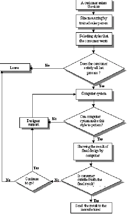
by the customer‟s satisfaction and the computer system. Once the customers select all options and are satisfied, the information and pattern are sent to the manufacturer (Lee & Chen, 1999).
Figure 1. Structure of In-Store Service for Mass Customization (Lee & Chen, 1999)
measurement and the individual patterns are made by the alteration rule system. Once a set of marker making patterns is made and a cut file is generated, the garment is cut and sewn.
Fiore, Lee, Kunz, and Campbell (2001) presented body scanning and co-design process to subjects, and then they asked about their levels of interest during their research. Because Fiore et al. (2001) thought that two important procedures for mass customization of apparel options were body scanning for better fit and co-design for a unique design. First, body scanning involves using electronic measurements of the customer's body form to develop a manufactured product with an individualized fit. Second, in the procedure of co-design, the customer, generally with the aid of CAD technology and/or professional assistance, compiles an individualized product design from a company's style, fabric, color, surface design and size alternatives (Fiore et al., 2001). Fiore et al. (2001) found that subjects with high optimal levels of stimulation were more interested in co-design than those with lower optimal levels of stimulation. That is, subjects preferred experiential rather than utilitarian types of co-designed products.
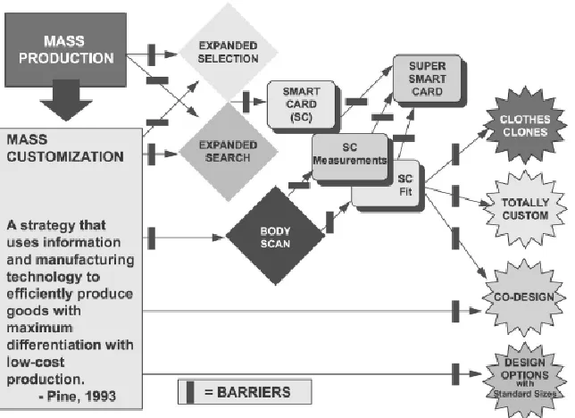
selection/search”; “design option”; “co-design”; and “total custom” (Anderson-Connell et al., 1998).
star shapes indicate the customization options emerging from the potential use of technology (Anderson-Connell et al., 2002).
Figure 2. Consumer Driven Model (Anderson-Connell et al., 2002)
the business community so that they can explore how the paradigm of mass customization could be applied as a business strategy in the apparel industry.
2.1.2. Apparel Companies for Mass Customization
Mass customization allows consumers to modify a company‟s product line to meet individualized design tastes or fit requirements. For example, many companies such as Levi Strauss & Co., Brooks Brothers Inc., Second Skin Swimwear Inc., Custom Foot Inc., etc. are now operating at various levels of mass customization (Lee & Chen, 1999). After examining ready-to-wear and perhaps trying on garments to establish fit and sizing, the customer may be beneficial from the development of individualized product specifications. For example, a customer may be able to choose individualized combinations of product style, fabric, color, and size from a group of options; he/she may create a unique design based on his or her preferences, or achieve personalized size and fit based on physical body measurements or body scanning; once specifications are developed, the customer may pay for the product, and the order is sent to the production facility; finally, the product is made and sent to the customer in a few days.
electronic devices to take body measurements. Clothing companies like Levi Strauss & Co. and Second Skin Swimwear Inc. use the measurements in order to customize garment size and fit. Therefore, now the body measurement information can also be digitally stored on a smart card for portability.
2.1.2.1. Levi Strauss & Co.
Founded in 1853 by Bavarian, Levi Strauss & Co. was the first large apparel company to provide mass customization through jeans, offering choices in style, fabric, finish, color, and inseam length. Jeans fit is determined by inputting the customer‟s measurements, which are acquired manually by a salesperson, and the customer‟s individual preferences into a computer program, and then having the customer try on sample jeans (Lee & Chen, 1999).
attempt to sell merchandise tailored or otherwise, online from its web site was curtailed in November of 1999, when the firm announced its intentions to sell via the web sites of two of its major customers, J. C. Penney and Macy‟s.
2.1.2.2. Brooks Brothers Inc.
2.1.2.3. Interactive Custom Clothes Company (IC3D)
In 1996, the Interactive Custom Clothes Company (IC3D) was launched. The IC3D focuses on mass customization and made-to-measure as its business strategy (Rio, 2001). IC3D's proprietary technology is a Genetic Engineered Neural Network (GENN) that generates made-to-measure patterns in a minute. This patent pending, "System and method for producing custom clothing," can be leveraged in a B2C, B2B and C2C model for the apparel industry. Measurements needed for custom clothing can be acquired either manually from a tape measure or digitally form a 3D full body scanner. In particular, the technology solved the inventory risk problem for apparel by offering great fitting garments in any styles and fabric. The IC3D enables consumers to choose their measurements for garment fit, thread colors, garment designs, etc. and has provided the public with custom made-to-measure jeans (IC3D, 2008).
Figure 3. IC3D Customer Eleven Measurements(IC3D, 2008)
2.2. Advanced Mass Customization in Apparel
Along with the rapidly growing power of information technology, the Internet has emerged as a compelling channel for the apparel industry. Consumers who are purchasing garments via online mostly rely on two-dimensional photos of garments and sizing charts when they decide on their final selection. However, this way of purchasing is not precise so that customers can choose their right sized clothing. Volino, Cordier, and Magnenat-Thalmann (2005) noted that the disadvantage of online shopping is that consumers can‟t try on clothing before purchasing. Therefore, a number of endeavors for solving the problem have arisen recently across the world. In other words, the combination of Made-to-Measure manufacturing and shopping via the internet comes to realization by the emergence of advanced technologies, systems and practices such as 3D body scanners, the customization of existing styles, and Virtual-Try-On visualization technologies (Volino et al., 2005; Cordier, Lee, Seo, & Magnenat-Thalmann, 2001).
2.2.1. 3D Body Scanning Technology and Fit
jeans. This program, called Levi‟s Original Spin, made others retailers stand up and take notice. Levi Strauss & Co. created many stock-keeping units (SKUs) of a product for mass customization and provided appropriately fitting size garments to customers. Lands‟ End promoted the world‟s first body scanning truck; the „My Virtual Model Tour 2000‟. Brooks Brothers Inc. placed a body scanner in their flagship store on Madison Avenue in New York City in 2001 (Istook, 2008). Brooks Brothers Inc. has provided mass-customized suit using 3D body scanner. The customer measurements collected by body scanner are used to make individual custom patterns and individual styles, fabrics, and designs are selected from a computer screen with trained sales‟ consultation. The manufactured garments are shipped to their stores and the information such as body scan data and patterns of customers are used for reorders (Cornell University, 2009).
Table 1. Three-dimensional scanning systems
Light Based Systems Laser Based Systems Sound wave/ other systems
Company Product Company Product Company Product
Hamamatsu Body Line Scanner C9036-02 Cyberware WBX, WB4,
WB4 Color Intellifit Intellifit
Loughborough
University LASS Hamano Voxelan
Puls Scanning System GmbH Puls Scanning System Human Solutions Virtus LC, Vitus XXL
[TC]² 2T4, 3T6, NX
12, NX 16 Polhemus FastSCAN
TELMAT Industrie SYMCAD 3D Virtual model, SYCAD Optifit Vitronic
Vitus Pro, Vitus Smart, Vitus Ahead, Pedus
Turing Turing C3D
Wicks and Wilson Limited
TriForm
Note: Taken from Istook (2008), p. 96
2.2.1.1. Telmat Industrie
SYMCAD Optifit is operational in several locations in France and in the UK. In the SYMCAD, two cameras are used to captures the frontal and lateral view of the human shape (see Figure 5). This system has used the horizontal grid line shadows seen on a human body during the scanning process (see Figure 6).
Figure 5. Telmat Industrie‟s 3D SYMCAD OptiFit system (Hamit, 2001)
Telmat Industire demonstrated how measurements could be stored all individual body measurements captured using SYMCAD Body Card based on the ISO standard (see Figure 7). The SYMCAD SizeMatch system having a size-selection table based on ISO 8559 can be integrated into the apparel CAD systems for mass customization.
Figure 7. SYMCAD Body Card information based on ISO 8559 (Hwang, 2004)
shape analysis and automatic posture classification (Telmat, 2008).
Figure 8. Automatic detection of anatomical landmarks (Telmat, 2008)
2.2.1.2. [TC]²
2009). Using the four images taken from each sensor, the phase at each pixel can be determined and then it is used to calculate the three-dimensional data points. A schematic of the sensor head with a projected plane of constant phase and camera ray (Cornell University, 2009).
Figure 9. [TC]²‟s triangulation between projector camera and subject ([TC]², 2008)
Figure 10. 3D point cloud data ([TC]², 2008)
Figure 11. Segmentation of the body ([TC]², 2008)
Figure 12. Printout available to subject ([TC]², 2008)
2.2.1.3. Wicks and Wilson, Limited
scanner has a total of four capture units and mirrors are used during this process to aid in capturing the body in two directions which ultimately produces eight views (Istook & Hwang, 2001). The images captured by the cameras are automatically passed to a PC controller that creates a 3D point cloud output. The initial lines of the body data are parallel and horizontal, but they are developed to the bend lines. The Triform BodyScanner automatically calculates approximately 1.5 million points to describe the position of the surface in 3D space. The whole body is capture in less than 10 seconds and is then processed to produce a full color three-dimensional image which can be displayed, measured in a variety of software applications (Wicks & Wilson Ltd, 2008). The 3D shape is a colored point cloud on the monitor screen that looks similar to a photograph of the subject. This software makes capturing 360 degree, full-color or mono 3D images a straightforward process.
Figure 14. Triform‟s moiré fringe technique (Wicks & Wilson Limited, 2008)
Triform has already been tested in a large garment sizing survey in the UK and it will be used in E-commerce for Internet shopping, in the medical field, in animation and multimedia, and in garment sizing for the apparel industry (Istook, 2008).
2.2.1.4. Cyberware
in which a strip of light is emitted from laser diodes onto the body surface. The light viewed from an angle is distorted by the objects shape and this distortion is recorded by the CCD sensors (Smith-Outling, 2007; Hwang, 2004).
The WBX scanner developed by Cyberware takes hundreds of thousands of measurements of the human body in just 17 seconds. The WBX scanner has four scanning heads that collect high-speed 3D measurements every 2 mm from head to toe to create an accurate 3D data set as shown in Figure 15. This scanner captures an array of digitized points, with each point represented by X, Y, and Z coordinates for shape and 24-bit RGB values for color. It was developed for use in acquiring measurement data used for apparel product development. The WBX version of the scanner collects all of the data required for clothing measurement extraction with a substantial reduction in complexity, size and cost (Cyberware, 2008; Istook & Hwang, 2001)
The WB4 called the Cyberware Whole Body Color 3D Scanner captures the shape of the entire human body and the RBG color image. The Cyberware Whole Body Color 3D Scanner (WB4) uses four scanning heads that are located on two vertical towers (see Figure 16). The individual stands on a platform between the free standing scanner towers and waits as the scanning heads move vertically down the tower capturing the whole body. The scanner's rapid acquisition speed freezes motion and makes it easy to scan many subjects or to capture different poses appropriate to the application at hand. This system is more complex to assemble and operate than the WBX scanning system (Smith-Outling, 2007; Cyberware, 2008). It was designed and manufactured as a portable tool for highly versatile and accurate scientific applications and has proven invaluable in collecting the data necessary to develop the measurement extraction capabilities required for accurate recruit sizing. However, the scanner has expensive features and then Cyberware developed the WBX version of the scanner in 2000 (Cyberware, 2008).
Cyberware's CyScan software provides an interactive control of the entire digitizing process. The models are viewed by several ways including Gouraud shaded, RGB color shaded, or shaded and texture surfaces. Cyberware‟s DigiSize Software is a complete solution to measure, size, analyzes, store and manage scan data from the Cyberware Whole Body scanners and is used to extract and store measurements to be used in various applications. The converted VRML (see Figure 17) files are used in web applications such as the individual image for digital garments (Cyberware, 2008; Smith-Outling, 2007).
Figure 17. VRML image with extracted measurements (Cyberware, 2008)
2.2.1.5. Human Solutions (TecMath)
Hwang, 2004). This company developed the RAMSIS, Contour, Move, and Vitus systems related to ergonomics and garment measuring systems. It is an articulated man model which can be interfaced with CAD models. In order to optimize the anthropometric background of the model, TecMath developed a whole body scanner. This system has two scanning heads in the front and back of the body and a laser stripe is projected on the body. The sides of the body are not represented in the scan by this method, but the input is sufficient to optimize the Ramsis model (Hein & Jeroen, 1998). TecMath also developed a package ergonomic that was designed to be a tool for accessibility and field-of-vision investigations performed on digital models, e.g. car interiors. By integrating a virtual human model in VD2 base modules, the real observer can map his own body geometry, movements and field-of-vision into a model (Human Solutions, 2008).
VITUS/smart 3D Body Scanner developed by Human Solutions consists of eight cameras and four eye-safe lasers. This scanner captures about 300,000 data points for each scan and the scan time is only 12 seconds. The resolution of the final scan is 1 mm increments horizontally and 2 mm increments vertically. The camera views overlap generously, providing a good scan image (Cornell University, 2009).
simultaneously process these postures for each subject person. ANTHROSCAN performs the landmark-based automated measurement process as well as supports the administration and processing of several body postures. The ANTHROSCAN system has a pre-defined measuring schemata based on ISO-8559 and ISO-7250 standards (Human Solutions, 2008).
Figure 18. ANTHROSCAN system of Human Solutions (Human Solutions, 2008)
2.2.2. Virtual Try-On
Virtual Try-on is defined as the computer simulation where customers can choose garments and try on 3D mannequins or avatars that are adjusted to their body measurements and are assisted to conduct proper online purchase of apparel (Cordier et al., 2001; Virtual Fashion Technology, 2007). In other words, consumers of the virtual apparel shop are able to simulate chosen garments on virtually simulated bodies with their own measurements (Loker et al., 2008; MIRALab, 2003). Figure 20 illustrates the main functional components of Virtual try-on infrastructures.
2.2.2.1. Virtual Try-On Overview
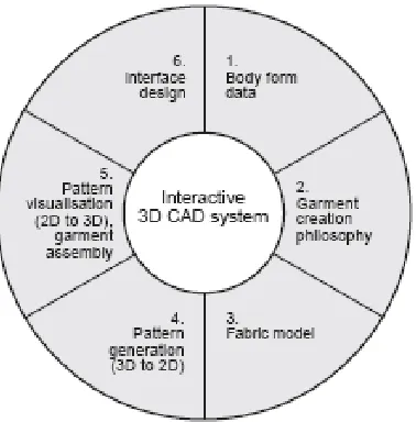
Hardaker and Fozzard (1998) discussed the key areas of several researches that contribute to the development of 3D CAD methods for the virtual garment. They described that “the garment design process as highly specialized, requiring a combination of design creativity and technical pattern making skills, as well as a thorough knowledge of fabric performance” (p.114). Figure 21 shows the key issues of the interactive 3D CAD system for the virtual garment (Hardaker & Fozzard, 1998).
Figure 21. The key issues of interactive 3D CAD system (Hardaker & Fozzard, 1998)
predict the shape of draped fabric. The fabric properties are measured by testing systems (e.g. Kawabata Evaluation System) and texture mapping is used for a virtual fabric. In the pattern generation step, a method to develop from 3D prototype to the 2D pattern shapes is required by a 3D CAD system. For the visualization of 2D patterns, the edges of the 2D pattern are sewn together and the stitched 3D patterns are positioned on a 3D avatar. The designers‟ interaction is also important for the success of a 3D CAD system (Hardaker & Fozzard, 1998).
Kartsounis, Magnenat-Thalmann, and Rodrian (2003) noted that the virtual try-on allowed online consumers to see themselves or to look at how well they match together between a model wearing simulated garments and their actual body measurements and shapes. Moreover, as a result of the enhanced consumer interaction with virtually modeled apparel products, customers became better informed when they made purchasing decisions (Fiore et al., 2005). In addition, establishing customer database of accurate measurements enabled customers to create avatars appropriate for them with accurate representation and clear images in a minute.
example, according to the findings of Loker et al.‟s (2004), the survey respondents selected the virtual try-on as the most influential technology that enable participants to buy more clothing on the Internet (Loker et al., 2004).
Divivier et al. (2004) developed innovative virtual reality technologies. To provide the virtual reality technologies, a complete process chain is being built up starting with the 3D scanning of the human body up to a photo-realistic 3D presentation of the virtual customer dressed in the chosen pieces of clothing. The customer was measured by a 3D laser scanner (Human Solutions GmbH) and the customer avatar with a smooth polygonal surface was created from the point cloud. For the virtual draping, the fabric material parameters are measured using the Kawabata Evaluation Systems. Two-dimensional patterns generated from DXF files were completed by the information of stitching, fastening, and material parameters. The virtual patterns were positioned on the virtual bodies and then the patterns were simulated (Divivier et al., 2004).
2.2.2.2. Virtual Try-On Technologies
Several CAD systems including Browzwear, Optitex, Lectra, and others have developed software for the apparel industry and they enable customers to try three dimensional garments on three dimensional avatars (Istook, 2008). The 3D avatars can be adjusted to general fit measurements such as the bust, waist, hip, abdomen, etc. Two dimensional garment patterns are set to „sew‟ together and then three-dimensional patterns sewn by virtual stitch are put on three-dimensional body and simulated three-dimensional garments demonstrating the drape of the fabric. The 3D virtual try-on technologies allow customers to try the 3D garment on the 3D avatars with their body measurements and to select other specifications such as silhouette, fabric, color, and embellishments. Customer used virtual try-on technologies can evaluate clothing fit over the Internet (Istook, 2008).
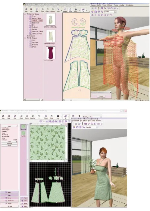
2.2.2.2.1. Browzwear
such as V-Stitcher™, V-Styler™ and C-Me™ recognized as the best commercial applications on the market for 3D visualization and design of garments and materials.
V-Stitcher™ and V-Styler™ 3D design and fitting applications is used by retailers and manufacturers, product development specialists, pattern makers and designers, as well as buyers and merchandisers. They rationalize the design and product development cycles by digitalizing much of the current pre-production process. Their solutions allow designers and manufacturers to get superior products to market faster and at lower cost. While C-Me™ is used by the consumer with an online personalized 3D visualization solution, retailers can also take advantage of the power of C-Me™ to complement their online and multi-channel sales techniques (Browzwear International Ltd., 2008). Browzwear developed parametric avatars including male, female, and children and improved simulation and functionalities for the accurate fit garments. Also, Browzwear launched Stylezone that is an online fashion community oriented towards teenage girls and fashion fans (Techexchange.com, 2008, March 2).
new anatomically accurate baby avatar and big-size woman avatar (Apparel Magazine, 2008).
V-Styler™ is a 3D garment design application that gives designers the freedom they need to see their ideas in endless true-to-life 3D simulations without the cost in time and material required to develop physical samples. V-Styler takes 2D design, adds fabric and texture, and turns it into realistic 3D garment visualization. Based on proprietary software, V-Styler offers the most powerful draping capability features currently in existence (Browzwear International Ltd., 2008).
Browzwear developed C-me for real-time collaborative fitting and design sessions in the Business-to-Consumer (B-to-C) environment. It enables customers to share collections with buyers, suppliers and retailers at any time during the pre-production, production and merchandizing process. Browzwear‟s C-me was already launched commercially in 2001 with the XOXO site. With C-me, customers are currently able to share the experience with friends for instant feedback (Browzwear International Ltd., 2008).
2.2.2.2.2. OptiTex
Founded in 1988, OptiTex USA, Inc. specializes in the development of innovative easy-to-operate 2D-3D CAD/CAM solutions and offers the convenient option of purchasing a completely integrated CAD package, including OptiTex software solutions, digitizer, and pen or ink jet plotter (Techexchange.com, 2008, May 27). OptiTex also focuses a 3D virtual try-on technology via the internet. In 2001, OptiTex introduced 3D4B2B that 2D patterns can be simulated onto a customer 3D avatar on a Business-to- Business web site and the 3D4B2B can be used in interaction with PDS systems and body scan systems (Hwang, 2004).
Pattern Design System (PDS) of OptiTex currently offers intuitive and powerful textile software tools designed for drafting new patterns or editing existing pattern pieces. OptiTex 3D Runway software is a realistic cloth simulation/ cloth modeling software system based on accurate CAD patterns and fabric characteristics (OptiTex, 2008).
2007, July 17). In the OptiTex software, a tension map is used to inspect amounts of stretching, tension and distance between the model and the cloth through a colored map as shown in Figure 24.
According to OptiTex USA, Inc. (2008), patterns can be imported from any CAD system as the file formats including DXF, AAMA, ASTM, HPGL-2, and MicroJet. The models can be imported from other 3D systems as the file formats including Model Files (*.mod), Cloth Files (*.clt), 3D Studio Max Files (*.3ds), Maya Files (*.ma,*.mb), VRML2.0 Files (*.wrl), STL Files (*.stl), AutoCAD Files (*.dxf), PLY Files (*.ply), Body Morph Files (*.mrp), Measure Files (*.ord), Biovision BVH Files (*.bvh), and OBJ Files (*.obj). Customers include Land's End, Target, Kohl's, COACH Leather, ABS by Allen Schwartz, Cherokee, Teamwork, Parachute De France, and Tyco Toys (Optitex, 2008).
Figure 24. A tension map generated by OptiTex software (OptiTex, 2008)
2.2.2.2.3. Lectra Systems, Inc.
Founded in 1973, Lectra Systems, Inc., one of leading CAD/CAM suppliers to the apparel Industry, provides made-to-measure solutions that offers a wide range of pattern, color, fabric, and fit (Lectra System, 2008). Lectra System has provided CAD/CAM software combined with the 3D body measurement technology developed by Human Solutions (Tecmath). The body measurements determined by the 3D body scanner allows customers to select the best fitting sizes and the customized garments (Hwang, 2004).
25 (Techexchange.com, 2008, June 12). Modaris 3D Fit enables the various garment models in three dimensions involved to validate garment styles, materials, motifs and color ranges directly on screen, as shown in the Figure 26 (Lectra Systems, 2008).
Figure 25. A tension map of Lectra Systems (Lectra Systems, 2008)
2.2.2.2.4. Gerber Technology, Inc.
Gerber Technology, Inc. is a leader company of CAD hardware and software systems to the apparel industry. Gerber Technology, Inc. provides several tools for Made-to-Measure (MTM) and mass customization as custom-made to an individual‟s style and fit (Hwang, 2004).
In 1999, Gerber Technology, Inc. introduced virtual draping program that can transfer from a 2D flat pattern to a virtual 3D dress from. For example, „APDS-3D‟, „Pattern Design‟, and „AccuMark MTM‟ were developed for Made-to-Measure (MTM) and mass customization as custom-made (Hwang, 2004). In the APDS-3D software, fabric designs were imported from Gerber‟s „Artworks StudioTM‟ program and a dress form was created from actual customer body measurements as shown in Figure 27.
Gerber Technology, Inc. currently uses Accumark V-Stitcher software for the virtual try-on technology. Two-dimensional patterns of Gerber AccuMark PDS software are transferred into Accumark V-Stitcher software. It interfaces seamlessly with AccuMark pattern design, grading and marker making software, enabling a fast and easy transformation of 2D patterns into 3D garments. This software enables seamless integration between its AccuMark pattern design software and Browzwear's V-stitcher application (Gerber Technology, 2008).
2.2.2.2.5. Tukatech
Tukatech was founded in California in 1997 and it has launched a new CAD product that can help reduce sample approval and production time by allowing the entire supply chain to visualize garments via the Internet and share input simultaneously (Tukatech, 2008).
In 2004, Tukatech introduced a new software product called 'e-fit Simulator' software. This software creates a virtual garment from a two-dimensional pattern and simulates on a 3D body model. The 'e-fit Simulator' software provides a set of fabric values such as stretch, weight, etc. as well as CAD patterns (Tukatech, 2008). The same patterns used to cut actual samples are used by e-fit Simulator, and the virtual fit models are created using body scan data of real fit models. With the 'e-fit Simulator' software, many kinds of garments with buttons, fish darts, slashes, gathers, plackets, belt loops, pocket facings/bags, etc. can be can be created (Tukatech, 2009). It also allows designers, pattern makers and manufacturers to make fit comments and modify patterns/ designs (Just-style.com, 2004, August 9).
2.2.2.3. Virtual Try-On Apparel Websites
Virtual try on technology is used to apparel websites. My Virtual Model is a leader of the virtual try-on concept for apparel online shopping.
2.2.2.3.1. My Virtual Model (MVM)
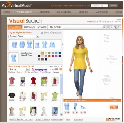
My Virtual ModelTM Incorporated, founded in 1993 as Public Technologies Multimedia Incorporated (PTM), provides retailers and their customers with online apparel shopping technologies and services. Virtual try-on is currently offered to online retailers by My Virtual Model (www.mvm .com), a Canadian company that has led the technology development. In 2001, „My Virtual ModelTM‟ offered „My Virtual Model Dressing Room‟
and „My Virtual Model Fit‟, which enabled users to try on clothes as well as size, color, and design over the Internet (see Figure 30).
MVM allows customers to interact with a 3D model which is rotated a full 360 degrees as shown in Figure 31. The company's My Virtual Model Imail™ product, launched in 2002, supports the integration of My Virtual Model Dressing Room with e-mail messages. It allows retailers to send personalized messages to customers (My Virtual Model, 2008).
My Virtual Model is available online Land‟s End, Sears, H&M, Adidas, Speedo, Levi Strauss & Co., Nutri/System, Lane Bryant, Crossing Pointe, Kenneth Cole, WeddingChannel.com, Orvis, Plussize.com, etc. for virtual try-on. Recently, Levi Strauss & Co. Signature and Prevention.com allows customers to use a virtual model using a weight loss simulator. A consumer is able to evaluate how the jeans look her now and when she reaches her personal goal weight (Lee, 2007). Shoppers who use My Virtual Model (MVM) are 26% more likely to purchase and spend 13% more than those who do not use this feature on a site (Nantel, 2004). This indicated that the 3D virtual model technology assists consumers‟ confidence in their final purchase decision by giving them access to an interactive virtual try-on session. MVM is associated with portals and virtual social networks such as Facebook, iVillage.com and gURL (Just-style.com, 2001, June 22). My Virtual Model allows customers to be able to superimpose a photo of their own face onto their 3D virtual model using www.hm.com. At this site, consumers can personalize their avatars and achieve greater satisfaction in their shopping and social experience (Montréal, 2007).
and fit of the selected garment on their body (Istook, 2008; Loker et al., 2008). However, My Virtual Model has still problem for the fit because this system was designed as the limited body sizes (see Figure 32). For example, there are just three body shapes including “hourglass”, “triangle”, and “inverted triangle”, just two choices including small-medium and medium-large in the bust size section and two choices including undefined and well-defined in the waist size section, although customers have many different body sizes and shapes (Istook, 2008). To simulate more accurate fit of the clothing on the body, consumers need to be measured using a 3D body scanner and their body data are input into virtual try-on software to create their exactly sized avatar.
2.3. Summary of Literature
3. METHODOLOGY
The major objective of this research was to evaluate the fit and appearance of virtual try-on garments and develop an exchange between a database of three-dimensional body scanning systems and virtual try-on software. Figure 33 shows the methodology for this study which has been created to compare a product developed in a virtual garment with the real garment. Initially, it is essential to measure a real body using a 3D body scanner to make virtual avatars and garments.
3.1. Body Scan Data (Objective One)
The first objective of this study was to utilize software that can take dimensional body scan data, transfer it to virtual try-on software, and make three-dimensional virtual avatars.
3.1.1. Initial Sample Collection
A sample of women and men were obtained via convenience sampling methods. They were located primarily from the Triangle area of North Carolina. The primary way of selection were through recruitment of students and employees at North Carolina State University‟s College of Textiles and were 18 years old or older. Also, any visitor to the College of Textiles wishing to participate in this study was invited.
3.1.2. Body Measurement
3D measurements of the body and the 3D body images were saved in the computer in .RBD, .ORD, .VRML and .BIN file formats.
3.1.3. Final Sample Selection
Consumers have many different body shapes. Shape could have an impact on the perception of fit in both a “real” and a “virtual” world. Nine shape categories including Hourglass, Oval, Triangle, Inverted Triangle, Rectangle, Spoon, Diamond, Bottom Hourglass, and Top Hourglass were identified by the Female Figure Identification Technique (FFIT) for apparel developed by Simmons, Istook, and Devarajan (2004) at NCSU.
For the purpose of this study, the top five shapes identified from Simmons research (2002) and Size USA (2002) were selected as the five body shapes of interest. These included the Rectangle, Hourglass, Bottom Hourglass, Oval, and Spoon.
3.1.4. Three-dimensional Avatar from [TC]
2Body Scan Data
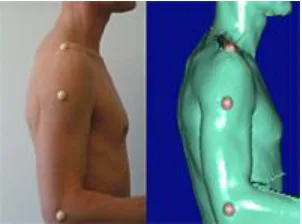
To create a 3D avatar from [TC]2 body scan data, the raw point cloud data captured by the body scanner were transferred to morph avatar data smoothed surfaces. Figure 34 shows the three-dimensional images of different body data of [TC]2 body scan.
Figure 34. Scan data processing for 3D avatar
was used to fill the missing data of the body‟s surface. As shown in Figure 34, a morph avatar (Polygonal mesh model) was created.
3.2. Generating Avatars (Objective Two)
The second objective was to make 3D avatars using 1) the direct method transfer from body scan data and the manual method input from body measurements. The second part of the objective was to compare the difference among these avatars.
3.2.1. Direct 3D avatar from [TC]
2body scan data
To create a 3D virtual avatar directly transferred from [TC]2 body scan data, the morph model data of [TC]2 body scan were directly imported to OptiTex software. The data were opened into the „Load Model‟ tool and then the direct 3D virtual avatars were automatically displayed.
3.2.2. Manual 3D avatar from body measurement
„OptiTex_Modulate_and_Model‟ MEP file was created for the Eva avatar of the OptiTex software and a „V-stitcher‟ MEP file was created for the Sara avatar of the V-stitcher software. After these MEP files required for the original avatars‟ measurements were set up, the .rbd files of the final subjects were extracted by the „OptiTex_Modulate_and_Model‟ and „V-stitcher‟ MEP file.
Table 2. Measure names between OptiTex and [TC]2
Measure Names of Model Properties Window (OptiTex) Measure Names of MEP File ([TC]2) Basic
Height Height
Size (underbust) Size
Height
Cervical Height CervicalHeight Shoulder Slope ShoulderSlope
Bust Height BustHGT Underbust Height UndBustHGT
OutSeam OutSeam
Crotch Height Inseam Hip Height HipHeight High Hip Height HighHipHeight
Knee Height KneeHGT
Length
Armscye Depth (vertical) ArmscyeDEPTH
Bust Point to Bust Point (horizontal) BPtoBP
Waist To Hips Waist2Hips
Across Shoulder Shoulders
Arm Length from Shoulder ArmsLength
Girth
Mid Neck MidNeck
Neck Base BaseNeck UnderBust UnderBust
Bust Breast
Waist Waist
Hip Hips
High Hip HighHip
Thigh (Max) Thigh
Low Thigh (Mid) MidThigh
Knee KneeWidth
Calf Calves
Ankle Ankle
Upper Arm (Bicep) Biceps
Elbow Elbow
Table 2 shows the measure names between MEP file ([TC]2) and model properties window (OptiTex). Each measurement from MEP file ([TC]2) was input to the model properties window (OptiTex). After the .rbd files of the final subjects were opened, the files were extracted by „OptiTex_Modulate_and_Model‟ MEP file. In the NX16 software system, a visual line for each extracted measurement was automatically placed.
Table 3. Measure names between V-stitch and [TC]2
Measure Names of Model Properties Window (V-stitch) Measure Names of MEP File ([TC]2) Height
Height Height
Body Silhouette
Body Size Body Size Maternity
Torso
Neck Neck
Shoulders Shoulders Nape to Waist Nape to Waist Shoulder Slope Shoulder Slope
Cup
Bust Bust
Under Bust Under Bust
Waist Waist
Belly Belly
Hip Hip
High Hip High Hip
Legs
Outside Leg Outside Leg
Inseam Inseam
Thigh Thigh
Knee Knee
X/O Leg
Calf Calf
Ankle Ankle
Foot Length Foot Width
Hands
Armhole Armhole
Over Arm Over Arm
Biceps Biceps
Elbow Elbow
Arm
Wrist Wrist
![Figure 9. [TC]²‟s triangulation between projector camera and subject ([TC]², 2008)](https://thumb-us.123doks.com/thumbv2/123dok_us/1760461.1226269/41.612.203.401.179.322/figure-tc-s-triangulation-projector-camera-subject-tc.webp)
![Figure 10. 3D point cloud data ([TC]², 2008)](https://thumb-us.123doks.com/thumbv2/123dok_us/1760461.1226269/42.612.100.535.67.310/figure-d-point-cloud-data-tc.webp)