UPLIFT OF BASE RAFT: CASE STUDY OF 500 MWe FAST REACTOR
Abdul Gani H.I., Ramanjaneyulu K.V.S, Sivathanu Pillai C.
Civil Engineering Division, Indira Gandhi Centre for Atomic Research, INDIA
ABSTRACT
Uplift of base raft of an NPP is of critical importance as it governs the design and thickness of the base raft and has implication on the overall cost of the project. Literature on the analysis and uplift behaviour of NPPs and other structures in general are examined. As a case study, base raft analysis is presented for Nuclear Island Building of Prototype Fast Breeder Reactor (PFBR 500 MWe). The factors influencing the base raft uplift, such as ground water table, load combinations, provisions based on International standards etc, and their implication are discussed. Computation of lift off involves estimation of overturning moments from seismic analysis, estimation of restoring forces from gravity loads, estimation of ground water table, combination of three components of earthquake, and finally performing of contact analysis for the assumed combination of loads. In case of PFBR, as this being the first fast breeder reactor on a commercial scale, a conservative approach is adopted for estimation of base raft uplift and the same is explained in this paper. The uplift phenomenon in base raft is unlikely to govern for PFBR, if the irrational conservatism is removed in the estimation of lift-off.
INTRODUCTION
PFBR, prototype fast breeder reactor, is a 500 MW(e) fast reactor meant for power generation. It is the first commercial breeder reactor in India. Various safety related buildings in the complex of PFBR are interconnected to enhance safety, strength and economy, resulting in a large shear wall framed structure, referred to as Nuclear Island Building (NIB). NIB comprises of Reactor Containment Building (RCB), Steam Generator Buildings (SGB 1 & 2), Fuel Building (FB), Rad Waste Building (RWB), Electrical Buildings ( EB 1 & 2), and Control Building (CB). All the buildings are supported on a common base raft of 3.5m thickness at a depth of about 18m from the ground where hard rock exists.
All structural members have to satisfy strength and serviceability, while the structure as a whole has to satisfy stability criterion. One more criteria, in the context of seismic analysis is the ‘uplift’ phenomenon, which has been recently introduced in safety standards for design of Indian Nuclear reactors [1]. It stipulates that, under earthquake excitation, foundation should not lift more than 30% of the raft area from the supporing medium. The computation of lift-off involves estimation of overturning moments from seismic analysis, estimation of restoring forces from gravity loads, estimation of ground water table, spatial combination of three components of earthquake, and finally performing of contact analysis for the assumed combination of loads. As PFBR is first of its kind in India, a conservative approach is adopted for estimation of base raft uplift. The study of the uplift phenomenon of base raft is critical both from safety and economy points of view as it governs the thickness of base raft.
In this paper, a brief review of literature on methods of base raft uplift analysis is carried out and as a case study the uplift analysis of Nuclear Island Building (NIB) of Prototype Fast Breeder Reactor (PFBR) and its implication in design of the base raft are enumerated.
REVIEW OF LITERATURE ON BASE RAFT UPLIFT
Different methods of analysis of base raft uplift considering the effect of mat flexibility and studies on the effect of uplift on the general response of the structure have been discussed in many literature. Many have favoured the view that dynamic uplift due to earthquake forces is beneficial from both strength and serviceability point of view [2,3,5,8,12-16].
Meek [2] investigated the effects of foundation tipping using a simple foundation consisting of two strip footings joined by a rigid slab. He found that tipping leads to a favourable reduction in the maximum transverse deformation suffered by the structure. According to Wolf JP [3], allowing the structure to lift off always leads to a reduction of the total horizontal accelerations and hence of the shear force, of the overturning moment and of the relative lateral displacement with the structure when compared to the corresponding linear analysis.
Kennedy, R P et al. [4] made a nonlinear analysis for investigating base slab uplift of a Gas Cooled Reactor with a lumped mass parameter model. Based on the above study, he concluded that linear analysis can be used to conservatively to estimate the behaviour of base slab during uplift in terms of overturning moments and percentage area of uplift. Yim, Chik-Sing et al. [5] investigated the rocking response of rigid blocks subjected to earthquake ground motion by numerical time stepping method. They found that the rocking response of a block is very sensitive to small changes in its size and slenderness ratio (H/B) and to details of ground motion. Also, overturning of a block by ground motion of a particular
Iyengar, R N et al. [6] studied the uplift of a typical NPP using nonlinear analysis on lumped mass model on circular rigid raft supported on uniform Winkler foundation with compression only springs. They found that uplift during SSE event reduced raft moments and shears marginally and linear analysis for FRS may not get altered considering uplift.
Many international standards have limited the uplift area of base raft for various reasons. In TecDoc 1347[7] , the foundation uplift due to earthquake is limited to 30 % of the foundation area as beyond that specific computations are required to find the influence of uplift on floor response spectra due to non-linear behaviour of the foundation. In Japanese codes [8] the foundation uplift is limited to 30% under OBE (Operating Basis Earthquake) conditions. Here the limitation on the uplift ratio is based on the considerations of accuracy of the structural response and the foundation bearing pressure which could be critical if bearing pressure is large. AERB[1] considers a loss of contact less than 30% of the plan dimension based on a simple equation as acceptable. For higher loss-of contact, a properly substantiated dynamic analysis is recommended to get realistic and less conservative estimate of uplift.
ESTIMATION OF BASE RAFT UPLIFT
The steps involved in the uplift analysis of base raft of NIB are as follows:
1) Three dimensional finite element model of NIB consisting of shell and beam elements is developed using finite element software. R.C walls and base raft are modeled using eight noded shell elements and beams and columns are modeled using 3-D beam elements. Figure 1 shows the finite element model of NIB, PFBR.
2) Foundation is modeled using discrete translation springs in three directions on each node on the base raft based on frequency independent impedance function formulation [9]. Range analysis is performed for 0.5, 1 and 2.0 times of shear modulus of the founding rock medium.
3) Free vibration analysis is carried out to extract natural frequencies and modes shapes. Response spectrum analysis is performed using site-specific response spectrum [Figure 2]. The modal combination is performed using 10% grouping method as prescribed in ASCE 4-98.
4) Based on the response spectrum analysis, the absolute acceleration values are obtained in each node where discrete mass has been lumped. The force acting in each node is computed as a product of acceleration and mass at that node. 5) A nonlinear static analysis carried out with the resulting nodal forces for different load combination. Successive
iterations are carried out by de-activating rock-springs in tension until convergence in raft deformation is obtained. 6) The analysis is repeated for different load combinations and the critical combination giving rise to maximum uplift
of base raft is identified.
7) Percentage area of lift-off of the base raft, bearing pressures under the portion of raft under contact with the rock and displacements of the raft are checked from the functional point of view
FACTORS INFLUENCING UPLIFT OF BASE RAFT
Effect of ground water table
PFBR is located at coastal town of Kalpakkam and at about 0.5 km from the coast of Bay of Bengal. The reduced level (RL) of Mean Sea Level (MSL) at the site is RL6.096 m. The average ground level at the site is RL 11.0 m. Ground Water Table (GWT) at the site varies seasonally from 2.0m to 4.65m below the existing ground level. The maximum ground water table based on bore-hole data from geophysical investigation carried out in 1985 is RL 9.0 m. This happened to be the maximum water level in the ground in 25 years and during the peak rainy season in December. The ground water table data from bore holes is shown in Figure 3.
Figure 4 shows the general ground level and water profile at PFBR site. For the purpose of estimation of uplift of base raft, the ground water level was conservatively assumed at RL 9.0 m. Based on nonlinear static analysis for uplift, it was found that the thickness of 2.5m of base raft is adequate to limit the area of uplift to 30%.
However, it was felt that to ensure safety, the ground water level for uplift calculation should be taken at finished ground level (RL 11.5). As a result the thickness of base raft was increased to 3.5 m to limit loss-of-contact to 30% of the raft area. This resulted in delay of the project by six months as repetition of the analysis and design was unavoidable.
AERB [1,17] does not mention about GWT in association with other loading events. In RCC-G [10], it is recommended to take into account variations in water table equal to 2m around the mean value as standard condition. Also in RCC-G, variation of GWT around its mean is combined with OBE load combination while in SSE load combination it is not included. Thus, the adoption of GWT at finished floor level for base raft uplift consideration along with SSE load combination is highly conservative.
Load Combination
The load combination used in the estimation of uplift of base raft significantly affects the uplift behaviour. The following load combinations are considered in the estimation of uplift in NPP.
0.9 DL + 1.0 EQX + 0.4 EQY + 0.4 EQZ + GWT (1)
1.0 DL + 1.0 EQX + 0.4 EQY + 0.4 EQZ + GWT (2)
where DL – Dead weight of the structure including equipment mass LL – Live loads on the structure
EQ(X,Y,Z) – Earthquake loads corresponding to Safe Shutdown earthquake in X,Y and Z directions respectively GWT - Hydrostatic Uplift due to Ground Water Table assumed at finished ground level
Figure 1: Finite Element Model for Nuclear Island Building (NIB), PFBR 500MWe
Figure 2: Site specific design response spectrum for PFBR 500
Monthly Average GWT from all Bore holes
6 6.5 7 7.5 8 8.5 9 9.5
Jan Feb Mar Apr May Jun Jul Aug Sep Oct Dec
RL
If uplift is treated as a stability concern, eqn (1) is to be adopted. Else, if it is a serviceability concern, eqn (2) is to be adopted. In case uplift is conceived as a boundary condition assumption dealing with soil springs, the seismic weight including 50% of imposed load too has to be included in eqn (2). By and large, opinions are not unanimous.
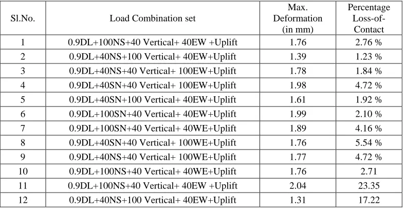
In case of PFBR raft, eqn (1) is adopted as a conservative measure. Table 1 shows results of the contact analysis for uplift of base raft for different load combinations with spatial variation of earthquake excitation.
In RCC-G[10], hydrostatic uplift due to GWT is combined with OBE load combination and in SSE load combination it is not included. Also, in Japanese codes the foundation uplift is limited to 30% under OBE (Operating Basis Earthquake) conditions [8].
TABLE 1 : RESULTS OF UPLIFT ANALYSIS INDICATING PERCENTAGE LOSS IN CONTACT BETWEEN RAFT AND GROUND FOR DIFFERENT LOAD COMBINATION
Sl.No. Load Combination set
Max. Deformation
(in mm)
Percentage Loss-of-Contact 1 0.9DL+100NS+40 Vertical+ 40EW +Uplift 1.76 2.76 % 2 0.9DL+40NS+100 Vertical+ 40EW+Uplift 1.39 1.23 % 3 0.9DL+40NS+40 Vertical+ 100EW+Uplift 1.78 1.84 % 4 0.9DL+40SN+40 Vertical+ 100EW+Uplift 1.98 4.72 % 5 0.9DL+40SN+100 Vertical+ 40EW+Uplift 1.61 1.92 % 6 0.9DL+100SN+40 Vertical+ 40EW+Uplift 1.99 2.10 % 7 0.9DL+100SN+40 Vertical+ 40WE+Uplift 1.89 4.16 % 8 0.9DL+40SN+40 Vertical+ 100WE+Uplift 1.76 5.54 % 9 0.9DL+40NS+40 Vertical+ 100WE+Uplift 1.77 4.72 % 10 0.9DL+100NS+40 Vertical+ 40WE+Uplift 1.76 2.71 11 0.9DL+100NS+40 Vertical+ 40EW +Uplift 2.04 23.35
12 0.9DL+40NS+100 Vertical+ 40EW+Uplift 1.31 17.22 Figure 4: Ground level and water profile at PFBR site
Sl.No. Load Combination set
Max. Deformation
(in mm)
Percentage Loss-of-Contact 13 0.9DL+40NS+40 Vertical+ 100EW+Uplift 1.87 25.53 14 0.9DL+40SN+40 Vertical+ 100EW+Uplift 2.35 25.56
15 0.9DL+40SN+100 Vertical+ 40EW+Uplift 1.54 20.69 16 0.9DL+100SN+40 Vertical+ 40EW+Uplift 2.30 28.63
17 0.9DL+100SN+40 Vertical+ 40WE+Uplift 2.12 27.32 18 0.9DL+40SN+40 Vertical+ 100WE+Uplift 1.93 26.54 19 0.9DL+40NS+40 Vertical+ 100WE+Uplift 2.07 26.01 20 0.9DL+100NS+40 Vertical+ 40WE+Uplift 2.03 24.64
Uncertainty in rock properties
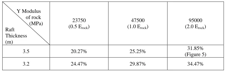
The analysis for base raft uplift is performed for range values of shear modulus, i.e, 0.5, 1 and 2.0 times of shear modulus of the founding rock medium. The shear modulus is found to significantly affect uplift of base raft. The variation in uplift of base raft for different values of modulus of rigidity is indicated in Table 2.
TABLE 2: PERCENTAGE UPLIFT FOR DIFFERENT RAFT THICKNESS AND MODULUS OF ELASTICITY OF ROCK (“0.9DL+Earth-pressure+Uplift+100% SN-SSE+40% WE-SSE+40% Vertical-up-SSE”)
Y Modulus of rock (MPa) Raft
Thickness (m)
23750 (0.5 Erock)
47500 (1.0Erock)
95000 (2.0 Erock)
3.5 20.27% 25.25% 31.85%
(Figure 5)
3.2 24.47% 29.87% 34.47%
OBSERVATION AND DISCUSSION
Following observations are made from the loss-of-contact analyses:
1) Load combination associated with 100% horizontal earthquake results in higher loss-of-contact, compared to combinations associated with 100 % vertical earthquake.
2) Loss-of-contact beneath the raft depends not only on the loads but also on the values of soil spring stiffness. Higher the soil spring value, higher is the loss-of-contact.
3) More clarity with regard to the loads, load combinations, estimation of over turning moments with response spectrum method and the procedure for estimation of uplift, will decrease the conservatism incorporated in PFBR raft thickness.
In AERB code [1], approximate method to determine uplift ratio of base raft is indicated based on assumption of infinite rigid raft, which can be conservatively adopted for flexible rafts as well. The contact ratio is given by,
Contact ratio = 3 (1/2 – Mmax/WL) (3)
Where Mmax is the moment derived from the linear seismic response analytical results, where foundation spring is treated as linear, W is the weight of the structure during seismic analysis. L is the dimension of the structure in the direction of application of the moment.
For PFBR, W = 1528900 KN, Mmax = 21712634 KN-M, L = 93m
Contact ratio based on eqn (3) = 1.04, for over all weight (Seismic weight) of the structure. This shows that the PFBR
effects due to ground water table. Also there is no mention about the spatial combination of earthquake to be considered for estimating uplift.
Figure 5: Loss-of-Contact and Bearing Pressure contours for Raft LC: “0.9DL+EP+Uplift+100%SN-SSE+40% Vertical-SSE+40% WE-SSE”
Foundation Modulus= 2.0Erock = 95000Mpa, Raft Thickness= 3.5m
Similar equation is indicated in [11], where it is stated that no repeat seismic analysis is required to be performed if the grounding/contact area obtained by equation (3) is more than 75%. Else, the linear rocking spring given in the code is to be replaced by tri linear rocking spring and the seismic analysis is to be repeated. In case of the non-linear rocking spring, if the contact area is more than 65%, then also repetition of seismic analysis is not required.
The base shear which prevails at the initiation of tipping is given as by YujiIshiyama [12]
Qcr = (E/H) * W (4) Where, E is the half breadth of the structure, H is the height of the structure and Weight of the structure
In case of PFBR, E = 92.3/2 = 46.15 m an d H = 75.5 m;
The minimum base shear which initiates the lift-off is = 0.611258W;
As the maximum base shear obtained from seismic analysis for PFBR is of the order of 0.2W, initiation of tipping is impracticable.
Yuji Ishiyama in his paper gives comprehensive plots giving criteria for rocking, and overturning for El Centro earthquake, Taft earthquake and Miyagioki earthquake. He considers combination of NS earthquake, EW earthquake and vertical
earthquake. As per the charts, PFBR raft shall not rock, or experience initiation of lift off for Elcentro earthquake too, whose PGA value is nearly 0.34g.
Studies conducted by Shiomi T et.al [13], indicate that a flexible raft experiences lower lift off than that of rigid raft. The diagram, showing comparison of experimental study with respect to analytical prediction of lift off for a flexible raft too is given.
From above discussion it can be concluded that the procedure adopted for the estimation of base raft uplift for PFBR under seismic conditions is highly conservative and the methodology may be looked into to formulate a more rational and practical procedures.
The following uncertainties are worthy of consideration in the light of the above discussion:
1) What is ‘W’ (Eqn 4)? It is not clear if it comprises only dead load or combination of dead load and live loads or fraction of dead load, say 0.9 times dead load.
2) Whether to consider buoyancy effects due to ground water table in the estimation of uplift?
3) If yes, how the uplift pressure on the base raft is considered in the equations for estimating loss-of-contact and what is the water table level to be considered and with what combination of loads?
4) How the hydrostatic pressure on the base raft is applied and in which area? The pressure can be applied only on those portions of the raft where there in no contact between the raft and rock.
5) What procedure is to be adopted for the analysis of uplift? The nonlinear static analysis based on the results on the response spectrum analysis is highly conservative as the response spectrum analysis gives the maximum response and consequently uplift, while nonlinear transient analysis although cumbersome may yield lower uplift as the raft uplift is transient in nature.
CONCLUDING REMARKS
1) The detailed methodology adopted for estimation of lift-off in base raft of NIB, PFBR is presented. Various parameters such as thickness of the raft, load combination adopted, consideration of ground water table, shear modulus of founding medium are found to affect the uplift ratio of the base raft considerably.
2) The methodology adopted is conservative from the estimation of lateral loads, choice of load combinations applied and estimation of ground water table.
3) Lift-off phenomenon is unlikely to occur for base raft of PFBR, if the irrational conservatism is removed in the estimation of uplift of base raft.
REFERENCES
1. AERB-SC-D, “Code of Practice on Design for Safety in Pressurized Heavy Water Based Nuclear Power Plants”. 2. Meek J. W, “Effects of Foundation Tipping on Dynamic Response”, Journal of Structural Division, July 1975
3. Wolf J.P, “Seismic Excitation with large overturning moments: Tensile Capacity, Projecting Base mat or lifting off ?”,
Nuclear Engineering and Design, Vol. 50, 1978,pp. 305-321
4. Kennedy et.al, “Effect of Non-Linear soil-structure interaction due to base slab uplift on the seismic response of a high temperature gas cooled reactor (HGTR)”, Nuclear Engineering and Design, Vol.38,1976.
5. Yim Chik-Sing et.al, “Rocking response of rigid blocks to earthquakes”, Earthquake Engineering and Structural Dynamics, Vol.8, 1980
6. Iyengar R.N et.al., “Uplift of a power plant founded on rock under seismic excitation”, Proc. of SMiRT Conference-9, 1987.
7. IAEA TECDOC 1347, “Consideration of external events in the design of nuclear facilities other than nuclear power plants, with emphasis on earthquakes”
8. Oshima R, and Tanaka K, “Realistic evaluation of Basemat uplift under seismic condition”, Proc of. SMiRT Conference
8
9. ASCE 4-1998 – “Seismic Analysis of Safety Related Nuclear Structures and Commentary”
10. RCC-G, “Design and Construction rules for civil works of PWR Nuclear Islands, Volume : Design”, 1988 11. 97TJP-290, “Technical Guide for Aseismic Design of Nuclear Power Plants”, JEAG 4601 – 1991 supplement
12. Yuji Ishiyama, “Motions of Rigid Bodies and Criteria for Overturning by Earthquake Excitations”, Earthquake Engineering and structural dynamics, Vol.10,635-650(1982)
13. Shiomi T,et.al, “Comprehensive evaluation of verification tests for seismic analysis codes part 3 rational model for uplift
14. Dowrick David J, Earthquake Resistant Design, John Wiley and Sons, 1987.
15. Koh Aik-Siong et.al, “Base isolation benefits of 3-D rocking and uplift I: Theory”, Journal of Engineering Mechanics, Vol.117, No.1, 1991.
16. Koh Aik-Siong et.al, “Base isolation benefits of 3-D rocking and uplift I: Numerical Example”, Journal of Engineering Mechanics, Vol.117, No.1, 1991.
17. AERB/SS/CSE-1, “Design of Concrete Structures important to safety of Nuclear Facilities”, 2001