Nupur Dinesh Chauhan et al,International Journal of Computer Science and Mobile Computing, Vol.3 Issue.6, June- 2014, pg. 796-801
© 2014, IJCSMC All Rights Reserved
796
Available Online atwww.ijcsmc.comInternational Journal of Computer Science and Mobile Computing
A Monthly Journal of Computer Science and Information Technology
ISSN 2320–088X
IJCSMC, Vol. 3, Issue. 6, June 2014, pg.796 – 801
RESEARCH ARTICLE
Image Fusion using Discrete
Wavelets Transform
Nupur Dinesh Chauhan
1, Manish N. Tibdewal
2¹ P.G. Student, Shri Sant Gajanan Maharaj College of Engineering Amravati University, Maharashtra, India 444203
² Dean Exam and faculty, Shri Sant Gajanan Maharaj College of Engineering Amravati University, Maharashtra, India 444203
1
[email protected];
2[email protected]
Abstract— This paper explains brief algorithm of image fusion using discrete wavelet transform, Where spatial and spectral both information were preserved in the fused image.. We have developed a robust technique to merge two multi focused images in to the one using wavelet transform. Image fusion achieved with DWT lifting scheme proves to be better than existing Image fusion techniques.
Keywords— Image fusion, Image processing, Wavelet transform
I. INTRODUCTION
Image fusion is the process of combining relevant information from minimum two images into a solo image
[1]
© 2014, IJCSMC All Rights Reserved
797
Fig. 1 Example of multi-focused image where top two image has only one toy in focus and bottom image has front most and rear most toy in focus.II. LITERATURESURVEY
The development of new multi imaging sensors has brought a need for image processing techniques. This technique should effectively fuse images from different sensors into a single image for interpretation [3]. Till now the image fusion has been considered primarily as a means for presenting images to humans. It may also be expected that fusion can become equally important in combining images, and hence in compressing source image data, for interpretation by computer vision systems saving the space [3]. An image fusion technique is successful to the extent that it creates a composite that retains all useful information from the source images, and does not introduce any noise that could interfere with interpretation.
The most direct approach to fusion is to sum and average the two source images but this produces unsatisfactory results.
Some of the most promising approaches to fusion are those that perform image combination in a pyramid transform domain: An image pyramid is first constructed for each source image, then a pyramid is formed for the composite image by selecting coefficients from the source image pyramids. Finally, the composite image is recovered through an inverse pyramid transform [4]. Several variations on pyramid-base fusion have been described in the literature [5]. These methods generally appear to provide good results. One limitation is in the fusion of patterns that have roughly equal salience but opposite contrast. This is a pathological case since image averaging results in pattern cancellation, and selection is unstable [6]. In satellite imaging, two types of images are available. The panchromatic image acquired by satellites is transmitted with the maximum resolution available and the multispectral data are transmitted with coarser resolution. This will usually be two or four times lower. At the receiver station, the panchromatic image is merged with the multispectral data to convey more information [1].
Many methods exist to perform image fusion. The very basic one is the high pass filtering technique. Later techniques are based on uniform rational filter bank [7], Laplacian pyramid [8] and one which we are using in this algorithm Discrete Wavelet Transform.
III.METHODOLOGY Algorithm consists of steps which are described as follows:
Nupur Dinesh Chauhan et al,International Journal of Computer Science and Mobile Computing, Vol.3 Issue.6, June- 2014, pg. 796-801
© 2014, IJCSMC All Rights Reserved
798
with our algorithm, weight propagation among subbands from parent to children, which by default we set to 1, smoothing at each subbands for noise reduction again set to 1 by default, show debug message for user to see message. The number of images is the input from the user taken by algorithm and by default we set it to two. Total number of decomposition affects the time of execution but also improves the accuracy. Wavelet decomposition for the Y component from YCbCr colour space is carried out. Debug messages such as 'Reading images and applying wavelet to them' are displayed during the execution of algorithm. In next step all the images are read and RGB colour images are converted into the YCbCr colour images. Next step is to initialization of the coefficient array to all zeros. After generation of blank array new weight matrix array and subbands are generated. For colour images wavelet decomposition for the Cb of YCbCr is carried out where as for grayscale image this step is not required. Similarly wavelet decomposition for the Cr of YCbCr is carried out in next step if image is colour. Next step is to generate J image which was achieved as follows: Take input from user as total number of decompositions by default is kept 6 after varying it from 1 to 16 we found optimum results were obtained at 6. In next step weight propagation among subbands from parent to children is assigned. Weight smoothing at each subband is optional step. By default debug messages were kept hidden. Foe proper operations image needs to be converted to 'double' from uint8.W which is 3D weight matrix is of the size (C, S) where C is wavelet coefficient image and S is wavelet sub-bands size. For denoising image Gaussian low pass filter of size 3, 3 was used which is almost a box filter. Next step is converting a map of usage index to a ratio map where coefficients are being converted as weights. Wavelet parents-to-child relationship is basically reweighting DC sub-bands from children to parent. Next step is to create the weight map of the approximation coefficient sub-band. Gaussian filter used to denoise is symmetric.
Next step in algorithm is deblur detail sub-bands by passing up and conversing the weight vectors. Here we need to interpolate to avoid showing 'divide by 0' error. Next step is to make new sub-bands filled up with focused coefficient. Wavelet transform used here includes: The size of output image obtained from the specified decomposition level. Next step is taking log to the base 2 and flooring the value. Now we extended image symmetrically. Once image is extended we performed the multi stage 2D wavelet decomposition using lifting scheme, where approximation coefficients of the image and number of decomposition level were the inputs to the algorithm from previous steps. Output argument were coefficient Image and size of the image with margin from top and left of each subbands. Margins were created by image padding with zeros. Decomposition function uses equal weightage from all input images. Scale factors selected were 1.15. Next step is to perform the multi stage 2 dimensional wavelet reconstruction using lifting scheme. Finally reconstructed image is shown in J variable and double to uint8 conversion was used for proper display of image.
IV.RESULTS
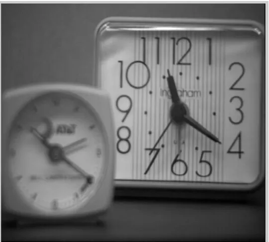
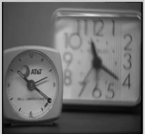
Figure 2 shows rear clock in focus as one of the input to the algorithm and Figure 3 shows same two clocks but this time front clock is in the focus. These two images were taken as the input images to our algorithm
© 2014, IJCSMC All Rights Reserved
799
Fig. 3 Input image showing front clock in focus and rear clock is out of focus.Figure 4 shows the resultant image which is fused. The resultant image gives more information than input images.
Fig. 4 Final output image after image fusion.
Nupur Dinesh Chauhan et al,International Journal of Computer Science and Mobile Computing, Vol.3 Issue.6, June- 2014, pg. 796-801
© 2014, IJCSMC All Rights Reserved
800
TABLEICOMPARISON OF DIFFERENT IMAGE FUSION ALGORITHMS
V. CONCLUSIONS AND FUTURE SCOPE
This algorithm mean pixel value falls in same range as that of most popularly used image fusion algorithms. Standard deviation is improved for almost all algorithms except mean but entropy is better than mean. Although the mean information is reduced correlation with input images are still very high. Fusion symmetry and noise proves to be better than most of the other algorithms currently in use. There are many applications of image fusion; few of them are listed below:
IR and visible images may be fused as an aid to pilots landing in poor weather.
Infrared and UV images for night of blind[15] vision
CT and NMR images may be fused as an aid to medical diagnosis [16].
ACKNOWLEDGMENT
We would like to thank our head of the department Dr. K. B. Khanchandani for the support. We would also like to thank our principal Dr. V. N. Gohokar for his support and motivation. We would like to take this opportunity to tank all the staff and management of Shri Sant Gajanan Maharaj College of engineering for facilities and infrastructure provided to carry out this research work.
REFERENCES
[1] http://en.wikipedia.org/wiki/Image_fusion
[2] http://www.mathworks.in/help/wavelet/gs/image-fusion.html.
[3] http://www.wisdom.weizmann.ac.il/mathusers/elishe/Seq2SeqFusion/Image_Fusion_technical_report.doc
[4] Li, Hui, B. S. Manjunath, and Sanjit K. Mitra. "Multisensor image fusion using the wavelet transforms." Graphical models and image processing 57, no. 3 (1995): 235-245.
[5] De, Ishita, and Bhabatosh Chanda. "A simple and efficient algorithm for multifocus image fusion using morphological wavelets." Signal Processing 86, no. 5 (2006): 924-936.
[6] Burt, Peter J., and Raymond J. Kolczynski. "Enhanced image capture through fusion." In Computer Vision,
1993. Proceedings., Fourth International Conference on, pp. 173-182. IEEE, 1993.
[7] Aiazzi, Bruno, Luciano Alparone, Stefano Baronti, and Andrea Garzelli. "Context-driven fusion of high spatial and spectral resolution images based on oversampled multiresolution analysis." Geoscience and
Remote Sensing, IEEE Transactions on 40, no. 10 (2002): 2300-2312.
[8] Li, Ming Jing, Yu Bing Dong, and Xiao Li Wang. "Image Fusion Algorithm Based on Wavelet Transform
and Laplacian Pyramid." Advanced Materials Research 860 (2014): 2846-2849.
Mean Standard deviation
Average Gradient
Entropy Mean information
Fusion Symmetry
Correlation Noise
Mean[9] 97.273 49.346 3.69 7.26 5.296 1.84 0.989 0.001
Maximum[10] 101.037 50.197 3.63 7.27 7.467 1.84 0.98 0.327
DWPT(mean − max)[11]
97.076 49.513 5.108 7.282 4.977 1.838 0.985 0.141
DWPT[12] 97.827 50.114 5.685 7.305 3.962 1.632 0.979 0.368
CV T(mean − max)[13]
98.565 49.119 4.566 7.414 4.007 1.838 0.985 0.092
CV T[13] 99.147 52.078 5.807 7.425 4.319 1.733 0.98 0.387
CNT(mean − max)[14]
97.097 50.117 8.538 7.468 3.885 1.871 0.972 0.158
CNT[14] 98.923 49.906 8.56 7.478 3.726 1.843 0.97 0.158
© 2014, IJCSMC All Rights Reserved
801
[9] Eberhardt, Knut, Oliver Ganslandt, and Andreas Stadlbauer. "Improved magnetic resonance myelography
of the lumbar spine using image fusion and volumetry: Clinical article." Journal of Neurosurgery: Spine
20, no. 2 (2014): 220-226.
[10] Joseph, Joby, and Alka Barhatte. "Medical Image Fusion Based on Wavelet Transform and Fast Curvelet
Transform." (2014).
[11] Amini, Nasrin, E. Fatemizadeh, and Hamid Behnam. "MRI-PET image fusion based on NSCT transform
using local energy and local variance fusion rules." Journal of medical engineering & technology 38, no. 4 (2014): 211-219.
[12] Sonn, Geoffrey A., Edward Chang, Shyam Natarajan, Daniel J. Margolis, Malu Macairan, Patricia Lieu, Jiaoti Huang, Frederick J. Dorey, Robert E. Reiter, and Leonard S. Marks. "Value of targeted prostate biopsy using magnetic resonance–ultrasound fusion in men with prior negative biopsy and elevated prostate-specific antigen." European urology 65, no. 4 (2014): 809-815.
[13] Jiang, Yong, and Minghui Wang. "Image fusion with morphological component analysis." Information
Fusion 18 (2014): 107-118.
[14] Sanchís, Carlos, Ángel Berenguer-Murcia, Ramiro Ruiz-Rosas, Emilia Morallón, and Diego Cazorla-Amorós. "Preparation of homogeneous CNT coatings in insulating capillary tubes by an innovative electrochemically-assisted method." Carbon 67 (2014): 564-571.
[15] Venkateswar, Sneha, and Ninad Mehendale. "Intelligent Belt for the Blind." International journal of science and research 3, no. 11 (2012): 1-3.
[16] Burt, Peter J., and Raymond J. Kolczynski. "Enhanced image capture through fusion." In Computer Vision,