Volume 2, No. 5, Sept-Oct 2011
International Journal of Advanced Research in Computer Science
RESEARCH PAPER
Available Online at www.ijarcs.info
ISSN No. 0976-5697
Reverse Engineering A Generic Software Exploration Environment Is Made Of Object
Oriented Frame Work And Set Of Customizable Tools
J.M.S.V.Ravi Kumar *, M.Babu Reddy, N.SreeRam and I. Rajendra Kumar
Lakireddy Bali Reddy College of Engg. Mylavaram, Andhra Pradesh , India
*[email protected], [email protected], [email protected], [email protected]
Abstract:
mainly research done to date on software maintenance has been focused mainly on the evolution of legacy systems based on out of date technologies. However, the use of more recent yet evolving technologies, like component-based techniques, also raise various issues about software comprehension and evolution. In particular, current industrial-strength component models like COM are based on many technical aspects that make them difficult to understand and use. The evolution of large module based software products is thus an rising issue. This paper presents GSEE, a Generic Software Exploration Environment. GSEE is made of an object-oriented framework and a set of customizable tools. Only few lines are needed to produce graphical views from virtually any source of data. GSEE has been successfully applied to improve the understanding of different software artifacts including a multi millions LOC software. Currently, two kinds of tools have been integrated in this environment: OMVT which is DASSAULT SYSTEMES specific, and GSEE which is a generic tool independent from the meta-model used.
Keywords: OM; DS;CB; UML; GSEE;
I. INTRODUCTION
Large software products have always been difficult to understand and evolve [10]. In the late 80’s this has leaded to the emergence of closely related techniques like reengineering, reverse-engineering and restructuring, collectively called RE3 technologies [26]. Traditionally, most research work in RE3 focused on the evolution of legacy software products based on obsolete technology. Many tools have been proposed to deal with old-fashioned programming languages such as Cobol, Fortran or C for instance. There is still a belief that the usage of RE3 techniques are restricted to legacy systems.
However, reverse engineering is defined as “the process of analyzing a subject system to: (I) identify the system’s components and their interrelationships and (2) create representations of the system in another form. This definition makes no mention about the level of maturity of the technology involved, nor the definitions of restructuring and reengineering do [ 1,6]. RE3 techniques have to follow the evolution of industrial software engineering practice. The wave model [21] is very valuable in this context, since it provides different.
Historical views on software engineering evolution. industry.
These waves of interest in forward engineering technology have an strong impact on RE3 evolution. For instance, in the mid go’s, the first restructuring tools focused on the shift from ad-hoc programming to structured
programming by removing goto statements from unstructured programs [2]. The shift from structured programming to modular programming also led to clustering and (re)modularization tools, tools to recover software architecture, etc. [1,3,15,16,19,27].
The increasing interest in object-oriented technology in the last decade, results today in the existence of large oo software products. However, every technology will show its limits when applied at large [4]. In particular, large software companies, pioneers in the 00-at-large approach, understood that the 00 paradigm is no silver bullet [7].
The existence of large 00 software products naturally give rise to significant research effort focusing on the intersection of 00 and RE3 (e.g. the Spool [16] and Famous projects [7]). Note that this last step in the evolution of RE3 discipline marks a discontinuity: RE3 techniques are no longer restricted to the maintenance of legacy systems, they can be applied for the evolution of state-of-the-art software products. Many researchers now believe that RE3 techniques must be smoothly integrated within the forward engineering process, leading for instance to the concept of round-trip engineering (a series of short forward and reverse engineering cycles).
may constitute the basis of the next significant wave of interest in industry. Dassault Systems (DS), the world leader in CAD/CAM, is a pioneer in this domain. This large software company has developed a proprietary component model which has been successfully used for years in the development of CATIA [28]. However, like other companies such as Microsoft or Sun, DS faces difficulties in teaching his component model. Understanding large CB software is not an easy task. The existence of these issues should not be surprising since the CB approach is still in its infancy and is usually not formalized.
This paper results from the collaboration between an Academic institution, the LSR laboratory, and one of the largest software company in Europe Dassault Systems (DS), in an attempt to deal with problems related to the evolution of large component-based software products. In particular, this paper shows how a reverse engineering approach can substantially improve the understanding of a CB software product, taking CATIA as a case study. The rest of this paper is organized as follows. Section 2 briefly presents the main features of the DS component model in an informal way. Section 3 describes how a meta model can be used to formalize the concept of component.
Section 4 shows how this Meta model can be converted into useful reverse engineer tools. Sections 5 The GSEE Customizable Tools. Section 6 concludes the paper.
II. THE DS COMPONENT MODEL
In the mid 90s, when DS initiated the development of CATIA V5 [28], it was rapidly discovered that 00 technology has serious limitations and in particular that C++ did not satisfy all of the requirements. The two most important aspects were the following: Concurrent engineering. C++ entities are too closely related: even a minor change may produce a dramatic number of recompilations. For large products and high concurrent engineering constraints, this is a major issue. Extension capabilities. The CATIA major customers and development partners have a need to be able to extend DS components with their own code, even without the availability of the source code [8]. To solve these (and other) issues, DS developed, on top of C++, a component model borrowing ideas from COM, Corba and Java. Here follows a very short and informal description of the "Object Modeler" (OM). Despite its name the OM is best viewed as a component model. This section first presents the main OM concepts, and then provides some information about its realization.
A. Conceptual Level:
Object Modeler components are pieces of code that can be manipulated through the use of interfaces. Interfaces can be seen as abstract proxies for real objects that receive client requests and forward them to the component implementing the interface. The interface concept helps in addressing the concurrent engineering issue, since it isolates interface clients from modification of the component implementation. To be more precise, a component is made of set of elementary pieces of code, called implementations (an implementation is realized by a C++ class). One of these implementations is called the base (of the component). Other implementations, called extensions, can be attached later to the base in order to extend the component. A fundamental feature is that extensions refer to the base, but
the base ignores that it is being extended. This allows a new extension to be added at a later time, without any need to recompile the base nor any of the other extensions.
The Object Modeler also provides several other mechanisms not described in this paper. For instance it supports the concept of delegation or conditional implementation.
B. Realization Level:
All concepts provided by the Object Modeler, are implemented in terms of C++ entities. For instance, interfaces and implementations are both represented by C++ classes. In fact, the realization level is much more complex since the mapping is not one to one: the realization of a single Object Modeler entity can produce many C++ entities. Moreover, for a given conceptual entity there are many realization choices: to improve performance and address other non-functional requirements, DS has designed and tested a wide range of realization techniques. All these techniques allow to build efficient components, but at the same time developing and maintaining these components is quite a complex task. To keep the control on the resulting software, Object Modeler concepts are translated into C++ code using patterns and naming conventions. This approach is very similar to those taken by other component models (e.g. [22]). In the case of Object Modeler, additional information is also inserted into the source code through the use of macros. This alleviates the burden of writing repetitive pieces of code. Some pieces of code are also automatically generated. Extra information is also provided in separate text files called dictionaries, containing tuples “component - interface - dll”. These files permit, at run time, to locate and load only the necessary DLLs required during an execution and therefore to increase performances.
C. Related Issues:
The Object Modeler has been successfully used to build very large software products (hundreds of applications made of thousands of components, developed by hundreds of software engineers). Several issues have been raised: Need for a conceptual view. Software engineers describe components using low-level mechanisms at the realization level (naming conventions, macro, etc.). Object Modeler conceptual entities are mixed with huge amount of C++ code. Need for a centralized description, Information about a single Object Modeler entity is often spread among many different files, including source code and dictionaries. Need of formalization. The Object Modeler component model is informally defined by means of a huge documentation. While very valuable, this documentation is often imprecise and many realization constraints are poorly documented. Moreover, since the realization techniques tend to evolve over time to ensure continuous improvement, the most accurate information is available from experienced software engineers.
how to build components, but they often find it difficult to know what went wrong when the software they have developed does not show the expected behavior. What is missing is a clear picture of the overall component structure at a conceptual level. The realization level is available, but it contains too many technical details. Reverse engineering provides thus a logical approach to these problems, since its goal is to “create representations of the system in another form or at a higher level of Abstraction” [6]. However, while most reverse engineering techniques deal with traditional and well-defined concepts, the problem here is to deal with the reverse engineering of component-based software systems, which is a rather new issue in the RE3 domain. Before trying to develop a reverse engineering tool, the first step is to give a rigorous definition of what a component is. This is what is done in the next section.
III. BUILDING A META MODEL
Defining the Meta model for the Object Modeler was the first step of our approach’. The key idea is to describe each concept of the Object Modeler model as an object-oriented item described using the UML notation [21]. The production of the Meta model has been a long process since the model is quite complex and is still slightly evolving. Describing the full Meta model is out of the scope of the paper; we rather emphasize the method and the main properties of this Meta model. One of the main interests of using a Meta model is that it makes it possible to define different views on it. This paper concentrates on a small but central part of the Meta model: how the components are built from bases and extensions. Here the Object Modeler is described only at the conceptual level, without giving any detail on the realization level. Furthermore, a few simplifications have been made to keep things simple.
A. Describing Components As Black Boxes:
While the OM model is quite sophisticated, from an external point of view, the OM is only based on two main concepts: components and interfaces. Clients of a component don’t have to know how this component is built. This idea is described in the UML class diagram presented in Figure 2 on the middle of the next page. Components and interfaces are linked together by a single association: a component can implement many interfaces (this is indicated through the * symbol near to the name of the role all Interfaces). Conversely, an interface may be implemented by any number of components.
B. Describing Component Items Separately:
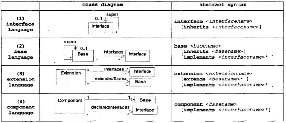
As it was said before, actually components are made of elementary pieces of software produced separately by software engineers. The concrete representation of these items in terms of C++ entities or other low level mechanisms like macros is not relevant from a conceptual point of view. So, instead of giving the many technical details required to describe those items, Figure 3 introduces four abstract languages. The first three represent abstraction of information contained in the source code, while the last one is the abstraction of “dictionaries”.
Each abstract language summarizes all the information required by the OM at the conceptual level. Note that, within the UML diagrams, arrows indicate unidirectional associations. For instance, an interface refers to its super
interface but not to its sub-interfaces. Similarly, an extension refers to the bases it extends, but not the other way around. Cardinality information also brings useful precision. For instance, from the Figure 3 we can learn that both interfaces and bases support single inheritance (roles named super).
Thanks to the Object Constraint Language (OCL) [25] provided with UML, it is also possible to: (1) define derived information, (2) describe additional constraints. As we will see in the Section 4, this is very important in practice. Consider for instance, the following OCL expression.
Figure: 2
Line 1 and 2 defines for each interface the all super role (not depicted in the figure), as being the set of all super interfaces for a given interface. This recursive definition provides an example of derived information. Line 3 uses this derived information to describe an additional constraint: the inheritance hierarchy between interfaces contains no cycle.
C. Linking Component Items Together:
Even if software engineers describe component items separately (that is required for concurrent engineering), one of the important aspects of the OM is how components are built from these items. Figure 4 shows a class diagram gathering the 4 languages described previously (these associations are drawn in black in the figure) and add derived information (in grey and prefixed by a ”/” symbol). Putting together component items must be done with an extreme care, not all combinations will work. Describing assembly constraint is therefore of fundamental importance. Indeed, this process leads to a great number of constraints that each assembly must satisfy to be considered as consistent. In the context of this paper, only two of these constraints will be described in Section 3.4 to illustrate the approach, but we first need to introduce the necessary derived information upon which the constraint are based.
This is what is done in Figure 5. The OCL expressions explain how components are made from implementations and define inheritance on components. Line 2 indicates that component inheritance (super) is in fact directly derived from base inheritance (base. Super). Lines 3 indicate that the extensions of a component (extensions) are all extensions attached to its base. Line 4 defines the direct implementation of a component (implementations). Line 5 recursively defines the set of all implementations (all implementations) of a component considering component inheritance. Line 6 defines the direct interfaces of a component. Finally line 7 defines the set of all interfaces (all interfaces) that can be reached from the component following either the interface inheritance relationship or the component inheritance relationship.
Gathering the four abstract languages (Figure 3) into a single diagram (Figure 4) helps to discover possible inconsistencies between the information they describe.
Indeed, the global view provided by a Meta model is one of the main benefits of the approach.
Figure 3. specification of component separately by means of four abstract languages
For instance, in our context, one should wonder what is the relationship between the derived roles declared interfaces and the explicit role all interfaces. After asking for more precision from OM designers, we learned that software engineers must explicitly declare all interfaces in the component language (i.e. in the dictionaries). So the next invariant is expected to hold.
Figure 4 . Component as Black Boxes
In practice ensuring this kind of constraint proved to be difficult, since the whole graph of entities is developed concurrently by hundreds of software engineers working in different sites, without a conceptual or global view. So, the meta model has to deal with inconsistencies. rather than ensure strict consistency. Therefore we comment out this constraint, so this is not an invariant of the meta model. This approach permits to represent "invalid" data. Next section will show how to locate these constraint violations in practice. While the constraint above can be discovered through the examination of the structure of the meta-model many other constraints require a better knowledge of the component model. For instance, one important requirement in the OM, is that the behavior associated by a component to an interface must be Unique; this means that, within a given component, an interface must always be associated to a single implementation.
Figure: 5
This expression translates the fact that two implementations of a component must not implement the same interface. The next section will give some examples showing how to locate and identify entities
Leading to such a constraint violation called multi-adhesion
IV. BUILDING REVERSE ENGINEERING
TOOLS
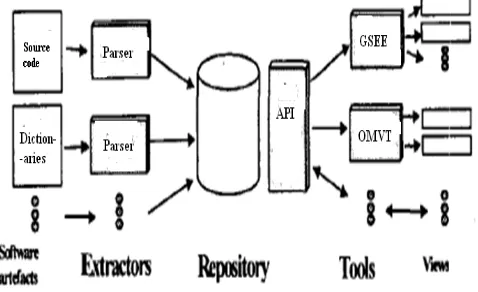
Building a meta model not only improves the understanding of the component model. It also provides a very good basis to build a reverse engineering platform on which a large set of tools can be built, ranging from simple visualization tools, to complex analysis or restructuring tools. This includes for instance, tools that detect constraint violation. Developing all these tools from scratch is certainly not cost effective. Fortunately, a common platform can be derived from the meta model.
A. A Reverse Engineering Platform:
Figure 6. The reverse engineering platform
As an illustration, the’ next section shows how the Meta model was used to build views displaying components using different visualization techniques. It then shows how inconsistencies can be found and located through the use of specific views. The realization level is far more complex. In this particular case, there were 49821 C++ classes involved in the concrete representation of these components.
B. Example Of Visualization Tools:
Displaying components was the first application of our reverse engineering platform. This was a very interesting experiment because components are built in a blind way (through the use of macros and other low level mechanisms spread out over many files), software engineers had never actually "seen" these components While the interfaces and implementations described above deal with the sources of data, visualization constitutes another important part of the GSEE framework. Indeed the interfaces required by visualization components are also expressed in terms of abstract structures based on the set theory: sequence, graph, tree, etc. In other words all data displayed by visualization is expressed in terms of type constructors that can in turn be expressed in terms of set and functions. This uniform treatment of components greatly helps the connection between source components and visualization components.
From a concrete point of view, GSEE includes a large set of visualization components. GSEE is based on the Java Bean component model [29] and makes an extensive use of the Swing framework provided with the java environment. In particular this framework provided valuable components to visualize a rich set of structures including sequences, tables, trees, hyper texts, etc. To complete the spectrum of visualization techniques, GSEE also integrates wrappers to various other visualization components, such as Grappa, the java version of the dot graph visualization tool [11]. We also have developed from scratch different visualization components such as tree maps and line sequences inspired from [6]. All visualization techniques currently available in GSEE have been selected for their ability to display very large sets of data. Tough a wide range of components are included with GSEE, it is still possible to add to the environment new visualization components dynamically, just like source components. This makes it possible to include specific components.
An interesting aspect of GSEE is that each visualization component described above has been encapsulated to support a uniform interface. All views are described in the same format: (1) a model specifies the software artifacts to visualize, and (2) a renderer indicates how these artifacts are
mapped to graphical entities. This approach followed by most modern visualization frameworks, is further improved in GSEE: both the model and the renderer can be expressed in terms of one or more successors, making it very easy to produce a new view.
To further simplify the production of renderers, the GSEE
framework also provides a set of interfaces and Implementations dedicated to visualization. For instance the interface Colorizer is intended to map objects to colors. The
EnumColorizer implementation maps a specified set of values to a specified set of colors (this is an example of function represented in extension since it is a set of pair (value, color)). Similarly RangeColorizer maps a range of values to a gradation of color, etc. Other implementations make it possible to combine these features. Some implementations are provided to edit the renderer properties interactively through the use of panels, color choosers, etc. and to save these renderers for further use. Since the renderers of each specific component are defined consistently it is easy to switch from a visualization technique to another. For instance, a hierarchical structure can be visualized using a Swing JTree, a graph displayed by a tree map, by just changing a parameter while keeping the same model.
V. THE GSEE CUSTOMIZABLE TOOLS
Usually one of the best ways to evaluate a software exploration tool is to see it at work. In the case of GSEE, it is important to keep in mind that the power of this environment is not directly visible since it resides first of all in the GSEE framework. However, in this section two demonstration tools included in the GSEE environment are briefly presented as an illustration of the approach: the GSEE
Interpreter and the GSEE Viewer. Though simple, these tools proved to be usable on a very large scale, in the context of Dassault Système [10,26], on a software made of more than 40 000 C++ classes. In the context of this paper, let us suppose that the goal is to explore the java standard library (more than 8000 java classes are delivered with the JDK1.3). The same tools can be used without any modification: instead of loading DS’repository at the beginning of the session a connection will be made to source components extracting information from java programs.
A. Example 1: The GSEE Interpreter:
The first demonstration tool is called the GSEE
Interpreter (see Figure 1). Thanks to the ramework, this tool is made of only 60 lines of java code!
a. Features. This tool aims to give access to the GSEE
language through a very rudimentary interface (see Figure 1). Simply put, the GSEE language is a functional language giving access to the compositional operators supplied by the framework.
saved to form a program for later use. In particular it is possible to create a specific tool from that program and make this tool available at large for novice explorers.
b. Example of A Scenario: To illustrate the use of the
GSEE Interpreter, let us assume that we want to study the relationship between the composition of packages and the inheritance relationship: for instance we want to know, for a given package P, which packages contain the super classes of the classes in P. In other words, we want to know if the inheritance relationship crosses package boundaries. We unlikely want to build from scratch a specific tool for that! Selecting adequate source components. So let us study the problem and see what we have at hand. Since building a java parser will be far too expensive let see which source components are available and how to extract the necessary information. Thanks to the java introspection library provided with the java environment, it is possible, for a given class to get its super class through the method getSuperclass. Unfortunately, this library does not provide enough support to deal with packages. For instance it is not possible for a given package to get the list of the classes it contains. Before starting to write a tedious piece of code, it is a good idea to check if there is on Internet some piece of code already providing this functionality. After a search among the many tools freely available (e.g. [1,3,15]), Java Assistant is found [4]. The main page describes shortly the functionality of the tool. In this page the following sentence is found “adavid.reflect.PackageFinder: finds all the packages on your system”. To get further information the tool is downloaded. Loading selected source components under GSEE. The JavaAssistant is a specific tool with a specific set of features. However, from the GSEE
point of view JavaAssistant could be considered as a source component since it provides some way to extract information from java programs. So let’s start a session with the GSEE Interpreter, and load this java component (see step (1) in Figure 1). Exploring source components. Since we have just loaded a new component, we do not know much about it. Fortunately, we can use GSEE to explore the software model implemented by this component: after all this is just another piece of software. Actually GSEE
supports the exploration of software models, that is, the exploration of meta information on software. This topic is an important feature of GSEE but is out the scope of this paper. This step has not been shown in the figure so the whole scenario can fit into the history window. What is important here, is that we learn that the method
getPackageResources gives access to packages.
Building new functions and getting the result. Before all, a short name is given for that method (2). The function is then tested on a package, for example java.lang.reflect (3). It seems to work, so we now define a successor use as being the function we need (4). The successor expression
package;getClasses;getSuperclass ;getPackage;getName means that we want “the names of the packages that contain the super classes of the classes contained in a given package”. The main benefit of an interpreted language is that we can try it immediately (5). From the output, we learn that the
java.lang.reflect package “uses” three packages, namely
java.lang, java.security, and java.lang.reflect. To get a global view, a function returning a graph is defined (6) and tested
(7). That's all we want. We have got the graph on the bottom of the window. As we can see, the core packages of java are strongly connected!
Figure: 7 A session with the GSEE Interpreter
Creating a new specific tool, we have just defined interactively a new function taking as parameter one or more package names and displaying the graph of inheritance over these packages. This function is useful so we may want to save the program we have just built and made it available to the whole team. Since other software engineers do not know much about the GSEE language, we supply them a specific tool with a simplified interface: a text field to enter the name of package and a panel to display the graph. This tool can be standalone or integrated as a plug-in in a programming environment. Currently GSEE is able to create plug-ins for the Kawa programming environment [16]. The function can be called directly from Kawa menus. The integration is therefore entirely transparent to the novice explorer. He can use its favorite programming environment without even knowing that this is actually a GSEE plug-in.
B. Discussion And Related Work:
a. About The Meta Model:
It is important to stress that this paper concentrates only on a small but central part of the OM meta model. The complete meta model is much more complex; it also describes the realization level (C++ classes, C++ inheritance, DLLs, etc.), larger grained entities like frameworks, products, etc. Describing precisely the constraints at these various levels proved to be difficult, mainly because the model evolved over time with the underlying technology and realization techniques. We also found that working only at the meta model level is insufficient, because it gives no information about actual instances. The first reverse engineering and exploration tools we have implemented provided us invaluable insights on the usage of the component model. For instance, we learned that some apparently important mechanisms are in fact almost not used at all. The reverse engineering tools also provided a great help in validating the meta model, through discussions with DS software architects and designers.
b. About Reverse Engineering Tools:
The platform is implemented in java, C++ parsers are developed by DS, and the repository is based on Object Store [30], a commercial Object Oriented Data Base. Various tools have been built around the platform. The OMVT tool, also implemented in java, represents a significant development effort, but it is clearly worth since it has been designed specifically to fit the needs of DS software engineers [23]. We also experimented with available RE3 generic tools, in particular with Rigi [19]. Our goal was to evaluate the current state of generic exploration tools and their capability to explore large component-based software products [20]. This experience show us (1) that it is easy to integrate new tool into our environment, (2) that getting first results with Rigi can take only few hours.
However, this tool also shows a number of limitations in our context [20]. We thus decided to develop GSEE, the Generic Software Exploration Environment [ 121. This environment has been used not only in the context of DS,
but also to explore other software artifacts. Indeed, GSEE can be seen as a generalization of the approach presented in this paper. Roughly speaking, this environment is parameterized by the meta model and enables software engineers to build “any” view on virtually arbitrary set of data, by just specifying the view in terms of the meta model [12]. Scalability and performance were considered as important issues during the design and the implementation of all the tools we have built. It is interesting to notice that the use of java do not raises performance issues. Actually, extraction from source code is the bottleneck of the reverse engineering process: it takes several hours to parse the whole software developed at DS (4 millions LOC in C++). This step is done once a week, and is integrated in the whole development process of the company.
C. Related Work:
Describing industrial component models in a rigorous way is gaining an increasing attention in the academic community. For instance, the COM component model has been described using the Z notation [24]. We preferred to use UML [22] and OCL [25] since these languages are increasingly popular in industry. A similar approach has been taken recently in the definition of the Corba
Component Model (CCM) [31]. In this case, the meta model is mostly seen as a documentation vehicle. Actually, the use of meta models has been widely recognized in software engineering, but most work aims at defining new models, or describing existing and stable models with well known properties (i.e. a programming language). This contrasts with our problem, since the OM component model is evolving and a very large amount of instances are already available. This last property naturally leads to RE3 techniques. In particular meta models have been used at the intersection of 00 and RE3 (e.g. Famous [7] is based on Famed, Spool [21] is based on UML). However, these projects model 00 concepts, not components. In this paper we have gone one step further: we consider that 00 programming languages correspond to the realization level, and components to the conceptual level. Finally, note that the Meta models we have built do not enforce strict consistency, but instead deal with inconsistencies.
In parallel with component-based approach, a very large body of work have been done in the academic community to define Architecture Description Languages (ADLs) [14]. These languages introduce the concepts of connector and configuration in addition to the concept of component. Unfortunately the ADL approach have failed so far to find its way to industry [ 17] in part because no support is provided to deal with existing software products. The lack of large industrial software products based on these concepts explain why most of research done in architecture recovery are usually based on traditional concepts like modules and dependency relationships (e.g. [15,16,19,27]).
VI. CONCLUSION AND FUTURE WORK
This paper represents a study of the intersection between reverse engineering and component-based software engineering. We believe that this topic will be of increasing importance as component technology will spread in industry. DS is pioneering in this domain. Tough this paper presents the platform as a reverse engineering platform, one of our goal is indeed to build a complete architectural environment to support the evolution of large software products [17,23]. This environment will also include forward engineering capabilities, and other RE3 techniques like impact analysis, restructuration, etc. All existing techniques need to be revisited to be applicable at the architectural level. We found that the use of the meta model is a very good basis to develop this kind of tool. Based on the understanding we have gained in this work, we are defining a new component model, along with the associated formalisms and tools. One way to validate this component model is to use it to develop our own platform and tools.
Our current research seeks to show, on the one hand, how to apply component-based technology to build RE3 environment like GSEE [12], and on the other hand, how RE3 can be applied to component-based technology.
VII. REFERENCES
[1]. R.S. Arnold; “Software Reengineering”, ISBN 081
8632720:200-213.
[3]. R.S. Amold; “Tutorial on Software Restructuring”, ISBN 0818606800, IEEE Computer Society Press .2004:204-213
[4]. L. Bass, P. Clements, R. Kazman; ‘Software Architecture in Practice”, ISBN 0201 199300, Addison-Wesley.2007:412-419
[5]. F.P. Brooks; “No Silver Bullet. Essence and Accidents of Software Engineering”, in IEEE Computer, April 1987.D. Box; “Essential COM”, ISBN 0201 634465, Addison- Wesley.:223-234.
[6]. E.J. Chikofsky, J.H. Cross; “Reverse Engineering and
Design Recovery : A Taxonomy”, in IEEE Software. 2000
[7]. S. Ducasse, S. Demeyer, editors; “The FAMOOS Object- Oriented Reegineering Handbook”2005: 323-328.
[8]. F. Duclos, J. Estublier, R. Sanlaville; “Open architectures for Software Adaptation”, (in french) 13th Intemational Conference on Software and Systems Engineering and their Applications.2003 :245-248.
[9]. R. Englander; “Developing Java Beans”, 0Reill:y &
Associates. Jun. 1997:(11):343-349
[10]. J.M. Favre; “Understanding-In-The-Large”, 5th
Intemational Workshop on Program Comprehension (IWPC’07), 2007:227-235.
[11]. J.M. Favre; “A rigorous approach to the maintenance of large portable software”, European Conference on Software Maintenance and Reengineering . 2005:434-440.
[12]. J.M. Favre, “GSEE: a Generic Software Exploration
Environment”, submitted to the Intemational Workshop on Program Comprehension (IWPC’2009).
[13]. M. Fowler, “Refactoring. Improving the Design of Existing Code”, ISBN 0201485672, Addison-Wesley, Nov. 2009.:320-330.
[14]. D. Garlan; “Software Architecture: a Roadmap”, in A.
Finke lstein, editor, The Future of Software Engineering, 22nd Int. Conference on Software Engineering, Jun. 2009.
[15]. R. Holt et al, PBS: Portable Bookshelf Tools. 2005:317-320.
[16]. R. Kazman, S.J. Camitre; “Playing Detective:
Reconstructing Software Architecture From Available Evidence”, Tech. Rep. CMU-SEI-TR-010, Software Engineering Institute, 2007.
[17]. Y. Ledru, R. Sanlaville, J. Estublier; “Defining an
Architecture Description Language for Dassault Systitmes”, 4th Int. Software Architecture Workshop, Jun.2007.
[18]. N. Medvidovic, R.N. Taylor; “A Framework for
Classifying and Comparing Architecture Description
Languages”. 6th European Software Engineering
Conference,.LNCS 1013, Springer-Verlag, Sep. 2007.
[19]. H.A. Muller et al, RIGI, S.T. Nguyen, J.M. Favre, Y.
Ledru, J. Estublier; “Exploring Large Software Products”, (in french), 13th International Conference on Software and
Systems Engineering and their Applications
(ICSSEA’2006), Dec. 2006.
[20]. L.B.S. Raccoon, “Fifty Years of Progress in Software
Engineering”, Software Engineering Notes, Vol. 22, No 1,
ACM SigSoft, Jan. 2007.
[21]. J. Rumbaugh, I. Jacobson, G Booch; “The Unified
Modeling Language Reference Manual”, ISBN 020130998X, 2005.
[22]. R. Sanlaville, J.M. Favre, Y. Ledru, “Helping Various
Stakeholders to Understand a Very Large Software Product” submitted to IWPC’2009.
[23]. K.J. Sullivan, J. Socha, M. Marchukov; “Using Formal
Methods to Reason about Architectural Standards”, International Conference on Software Engineering (ICSE’97), 2007.
[24]. J.Warmer, A. Kleppe; “The Object Constraint Language”, ISBN 001379406, Addison-Wesley, 2009:350-360.
[25]. E. Yourdon; “Re-3 : Re-engineering, Restructuring,
Reverse Engineering” in American Programmer, V01.2, No. 4, 2005.
[26]. S.T. Nguyen, J.M. Favre, Y. Ledru, J. Estublier, "Exploring Large Software Products", Proc. of ICSSEA, Paris, Dec 2000
[27]. D.E. Perry, "Software Interconnection Models", Proc. of the 9th Int. Conf. On Software Engineering, IEEE, March 2007.
[28]. S. Robitaille, R. Schauer, and R.K. Keller, "Bridging Program Comprehension Tools by Design Navigation", Proc. of the Intnl. Conf. on Software Maintenance, Oct. 2000.
[29]. S. Tichelaar, M. Lanza, S. Ducasse, "Moose: an Extensible Language-Independent Environement for Reengineering Object-Oriented Systems", Proc. of the 2nd Int. Symp. On Constructing Software Engineering Tools, June 2000.
[30]. R. Sanlaville, J.M. Favre, Y. Ledru, Helping Various