Volume 7, No. 7, Nov-Dec 2016
International Journal of Advanced Research in Computer Science
RESEARCH PAPER
Available Online at www.ijarcs.info
Modeling and Estimation of OFDM Based Power Line Communication Channels
H. R Singh
Deptt of Electronics & Comm. Engg Research Scholar, AISECT University,
Bhopal
prof.hrsingh@gmail.com
Sanjeev Gupta
Deptt of Electronics & Comm. Engg. AISECT University
Bhopal
sanjeevgupta73@yahoo.com
Abstract : The main objective of this work was to assess the suitability of Orthogonal Frequency Division Multiplexing (OFDM) vis-a-vis (Code Division Multiple Access) CDMA for Broadband Power Line (BPL) communication in rural areas. The work involved modeling of an OFDM based power line communication channel. A two-port network model was designed, developed and used in power line network distribution. In this paper, theoretical description and mathematical analysis of the same have been presented. The major portion covers the mathematical description of network distribution using the proposed decision–directed method for channel estimation and equalization in OFDM based Power Line Communication (PLC). This method uses chain parameter matrices describing the relation between input and output voltage and current of the two-port network. This method does not require a priori knowledge on the power line. Simulations on a realistic indoor power-line system show that the method achieves very good channel estimation and equalization performances and that, compared to CDMA, OFDM is robust to impulsive noise and nonlinearities, hence, suitable for deployment in rural areas for smart grid communication.
Keywords: Two-port, PLC, OFDM, Channel Estimation
I.INTRODUCTION
Information and Communication Technology (ICT) based services are no longer luxuries of life. These are essentials of day-to-day activities. The necessity of network enabled ICT in the communication starved rural areas needs no explanation, particularly in view of global digital transformation and digital economy entering a new age that presents unprecedented challenges, both in urban as well as rural areas. Many applications are operating at high speed and a fixed connection is often preferred. A broadband communication through the commonly accessible electrical power lines, eliminating the need of transmission of data over last mile through copper cable, short haul satellite systems, optical fibre cable and wireless technologies such as Wi-Max, Wi-Fi etc shall provide a reliable, robust and high speed communication alternative at much cheaper cost affordable by even the weakest sections of our society. This would bring about a tremendous breakthrough in communications. Every household would be connected at any time and services would be available at real-time. Using the power-line as a communication medium would be a cost-effective way compared to other systems because it uses an existing infrastructure (power-line network) connecting every home.
Power line communication (PLC) carries data on a conductor that is also used simultaneously for AC electric power transmission or electric power distribution to consumers. It is also called as power line carrier. The other reason for the power lines to find its application for data communication is its already established infrastructure and having the capability to switch the devices On/Off, especially those devices which consumes a large amount of power such as air conditioners, water heater etc. The advantage of this is to ensure a better management of energy which is more often called as Demand Side Energy Management. [1], [4].
The communication over Power Line usually alters in data rate in-accordance with the application and hence to differentiate the communication they had been categorized in frequency i.e. they utilize different frequency bands. Therefore,
the Power Line Communication is categorized as Ultra Narrowband, Narrowband and Broadband.
A.Ultra-Narrowband PLC
The first deployment regarding the UNB-PLC technologies involve the Turtle system and TWACS. Both system makes use of outbound communication for voltage (substation to meter) and inbound communication for current (meter to substation). The Turtle system has been mostly used for the Automatic Meter Reading, the first available products allows only one way communication whereas the two-way communication system became available after 2002. As the demand is increasing for higher data rates CENELAC EN 50065 standards allows communication over Low Voltage distribution PL in the frequency range from 3 kHz to 148.5 kHz.
The first deployment regarding the ultra-narrowband power line communication technology involves four frequency bands defined as [1]
1. 3-95 kHz: reserved exclusively to power utilities. 2. 95-125khz: any application
3. 125-140 kHz: in home networking systems with mandated carrier sense multiple accesses with collision avoidance protocol.
4. 140-148.5 kHz: alarm and security.
CENELAC mandates a CSMA/CA mechanism in the C-band and stations that wish to transmit must use 132.5 kHz frequency to inform that the channel is in use [7, 8]
B.Broadband PLC
The role of communication over power line is not limited to and for electric utilities only but also finds applications for smart grid which makes use of SCADA (Supervisory Control and Data Acquisition). The key problem associated with SCADA is the proper selection of architecture required for information gathering which would be needed to contain it [1].
Fig. 1 Block diagram of Supervisory Control and Data Acquisition (SCADA). 1,2,3 – Remote Stations
The basic model for the indoor power line channel and its circuit analysis had been defined which includes the wiring topological connection used in the residential and commercial premises which has a number of receptacles and outlet. In multi-conductor power line cables, usually two modes remain in existence – Differential mode and Common mode. Due to the presence of a number of shunt connections and impedance mismatches at these terminals, instead of a presence of a single path in between the transmitter and receiver there arises a condition of multiple paths from where the signal reflection occurs which causes a degradation in the signal quality with distance and time and the measure of it is defined by reflection coefficient which ranges from 0 to 1 [2, 3].
Fig. 2 Representation of Multipath signal propagation
Therefore, on the basis of this model the overall transfer function has been defined considering all the effects of attenuation, skin effect and dielectric losses while utilizing the scattering matrix or transmission matrix. [3, 5, 6].
II.BASICS OF POWER LINE COMMUNICATION
Power Line Communication is defined as a technology that utilizes high, medium and low voltage electrical networks to provide various services like voice and data transmission in addition to providing the power to the electrical utilities required for their operation.
In the initial stages, the power line communication was meant for deliverance of power only but as the time had ripen up it had started gaining more importance in high frequency applications, also known as Broad-Band Power Line. Since then these electrical networks had been used by the electricity producers and distributors for the purpose of remote controlling and network monitoring as well. It operates with electric power distribution system and provides a highly reliable means of communication among PLC devices which are electrically coupled to each other or located in proximity to the premises of
power distribution system. A system for PLC comprises repeaters, bypass devices, backhaul devices, wireless backhaul devices, communication interfacing units etc.
Although the power line communication has been defined on the basis of frequency i.e. the frequency band that it occupies. Moreover, it can also be defined corresponding to the voltage level i.e. Power Line Communication for High, Medium and Low voltage networks.
A functional block diagram shown in Fig. 3 of communication system in that channel indicates powerline.
Fig. 3 Functional Block model of Communication System
To outline a channel as a physical path between a transmitter and a receiver. Note that a low-voltage grid consists of the many channels each with its own characteristics. Fig. 4 below shows a digital communication system using the power-line as a communication channel. The transmitter is shown to the left and also the receiver to the right. Essential parameters of the communication system are the output impedance, Zt, of the transmitter and the input impedance, Zi, of the receiver.
A coupling circuit is employed to connect the communication system to the powerline. The aim of the coupling circuits are: Foremost, it prevents the damaging 50 Hz signal, used for power distribution, to enter the equipment. Secondly, it certifies that the main part of the received/transmitted signal is inside the frequency band used for communication. This will increase the dynamic range of the receiver and makes sure the transmitter introduces no meddlesome signals on the channel.
Fig. 4 A digital communication system for the power-line communication.
Fig. 5 indicates a model of the power-line channel with the parameters above. All impairments except the noise are shown as time-variant linear filters characterized by its frequency response. The disturbance is shown as an additive interfering random process.
Fig. 5 Power-line communication Channel Source
Source encoder
Channel
encoder Modulator
Channel
Destination
Source decoder
Channel
decoder Demodulator
Zi Zt
Transmitter Coupling
Circuit
Powerline Reciever
Coupling Circuit
Reciever Transmitter Hin(f,t) Hchannel(f,t) Hout(f,t)
N(t)
III.CHANNEL MODELING OF POWER LINE
COMMUNICATION
The determination of the transfer function of the power line is a non-trivial task since it depends on a number of variables, topology, network, cable parameters and impedances of the terminated appliances.
A.Transmission Line Model
The determination of the transfer function of the power line is a non-trivial task since it depends on a number of variables, topology, network, cable parameters and impedances of the terminated appliances.
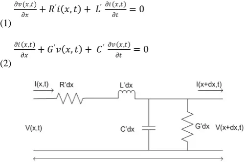
Various methods used to simulate and study the transmission line behaviour are described [9-11]. Most of them are obtained from the time dependent telegrapher’s equations which are for the elementary line transmission cell.
𝜕𝜕𝜕𝜕(𝑥𝑥,𝑡𝑡)
Fig. 6 Elementary cell of a transmission line
The Elementary cell of a transmission line is depicted in Fig. 6. In the above equations x denotes the longitudinal direction of the line and R', L', G' and C' are per unit length resistance (Ω/m), inductance (H/m), conductance (S/m) and capacitance (F/m), respectively. The electric quantities are dependent on the geometric and constitutive parameters. Transmission lines are described using the characteristic impedance Zc and the propagation constant γ:
𝑍𝑍𝑐𝑐 = �𝑅𝑅
The characteristic impedance Zc and the propagation
constant γ are related to the per-unit length parameters of the
transmission line. It is supposed that the per-unit parameters depend on frequency as [12].
𝑟𝑟=𝑟𝑟′;𝑙𝑙=𝑙𝑙1+ 𝑙𝑙2
�𝑓𝑓;𝑔𝑔=𝑔𝑔1𝑓𝑓;𝑐𝑐=𝑐𝑐1
Approaches for Modeling the Powerline Channel
Channel modeling consists of investigating the characteristics of the power network as a communication channel. PLC channels suffer from a number of technical problems, chief among them are:
Frequency-varying and time-varying attenuations of the
medium;
Dependence of the channel model on location, network topology and connected loads;
High interference due to noisy loads;
High non-white background noise;
Various forms of impulsive noise; and,
Electromagnetic compatibility (EMC) issues that limit
available transmitted power.
Two main approaches that can be utilized for modeling a powerline channel are described below.
1. Top-Down Approach
The Top-Down, or empirically based, approach is the most commonly used. This approach considers the communication channel to be a 'black box' and obtains the system parameters using experimental measurements of the powerline network. This approach describes the transfer characteristics of a channel by a transfer function. Using this approach in a multipath channel environment, the model characteristics can be established using experimental results. The major advantages of this approach are that little computation is needed and it is easy to implement. The major disadvantage stems from the fact that the channel model is vulnerable to errors in measurements.
2. Bottom-Up Approach
The Bottom-Up, or deterministically based, approach starts from the theoretical derivation of model parameters. This approach describes the behavior of a network by a large number of distributed components using matrices (scattering parameter matrices or four pole impedance and admittance matrices). Detailed knowledge of all components (cables, joints, connected devices) within a network is required for accurately setting up these matrices.
Developing a deterministic model basically means finding the transfer function theoretically without taking actual measurements of the transmission line. It is based on the intrinsic parameters (cable parameters, load impedances, etc.) of the network to establish a transfer function description of the channel.
These models generally require detailed knowledge about the components of the network to determine the elements of matrices.
The major advantage of this approach is its increased flexibility and versatility due to the fact that all the parameters of the network are formulated analytically, making it easy to predict the changes in the transfer function when a different multipath network configurations are under consideration.
The major disadvantages of the Bottom-Up Approach are 1.) Increased computational effort is required compared to
Top-Down Approach; and,
2.) There are a large number of parameters which cannot be determined with sufficient precision.
IV.MODULATION SCHEMES FOR PLCSYSTEM
constraints with regard to electromagnetic compatibility that limit the transmitted power.
A choice should be made of either a robust solution which provides sufficient quality for a wide range of variations of the model parameters, or an adaptive solution. The problem is further complicated in the home environment by the need to make powerline-based home networking cost competitive with other wired or wireless solutions.
The following modulation schemes are basically applicable for use in powerline communication.
A.OFDM
OFDM is a parallel transmission scheme where a high rate serial data stream is split into a set of low rate sub-streams, each of which is modulated on a separate subcarrier, thereby the bandwidth of subcarriers becomes small compared with coherence bandwidth i.e. the individual subcarriers will experience flat fading which allows the use of simple equalization. This implies that the symbol period of the sub-streams is made long compared to the delay spread of the time dispersive radio channel.
Therefore, a major requirement is to select a set of completely orthogonal signals; a high spectral efficiency can be obtained because of being completely orthogonal the mutual influence among the subcarriers can be completely avoided although the spectra of the subcarriers overlap with each other [14].
𝑠𝑠(𝑡𝑡) = � � 𝑐𝑐𝑘𝑘𝑖𝑖𝑠𝑠𝑘𝑘(𝑡𝑡 − 𝑇𝑇𝑠𝑠) 𝑁𝑁𝑠𝑠𝑐𝑐
𝑘𝑘=1
∞
𝑖𝑖=−∞
(5)
𝑠𝑠𝑘𝑘(𝑡𝑡) =�(𝑡𝑡)𝑒𝑒𝑗𝑗2𝜋𝜋𝑓𝑓𝑘𝑘𝑡𝑡 (6)
�(𝑡𝑡) =�0 1 0 <𝑡𝑡 ≤0,𝑡𝑡 ≤ 𝑇𝑇𝑡𝑡 ≥ 𝑇𝑇𝑠𝑠
𝑠𝑠 (7)
where,
𝑐𝑐𝑘𝑘𝑖𝑖= ith information symbol for the kth subcarrier
𝑠𝑠𝑘𝑘=Waveform for kth subcarrier
𝑁𝑁𝑠𝑠𝑐𝑐=Number of sub-carriers
𝑓𝑓𝑘𝑘=Frequency of kth subcarrier
𝑇𝑇𝑠𝑠=Symbol Period
∏(𝑡𝑡)=Pulse shaping function (rectangular in this case)
B.CDMA
CDMA stands for Code Division Multiple Access and it is a type of algorithm used to squeeze more usable channels within the same bandwidth. CDMA is a 2G technology and is one of the most widely deployed technologies. It is a multiple access technology that was introduced after TDMA and FDMA. Unlike TDMA and FDMA where the users are separated in terms of time and frequency, CDMA separates the users with separate code sequences. When we consider the CDMA system design, multiple access and interference handling are totally different from the narrow-band systems. In CDMA, each user spreads his signal over the entire bandwidth using direct sequence spread spectrum, whereas for the other users it is shown as pseudo white noise.
Parameters involved in this paper are shown, to obtain results of OFDM and CDMA, for performance of channel in terms of SNR value.
Table. 1 Parameters for Power-line communication Channel
Parameter Value
FFT Size 64
No. of used Subcarriers 64
Modulation Type QPSK
Series and Load Impedances 50Ω
V.RESULTS &CONCLUSION
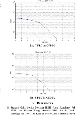
Results obtained by using MATLAB R2010a for OFDM and CDMA are shown below in Fig. 7 and Fig. 8 respectively. Signal to noise ratio is more in OFDM as compared to CDMA and also BER is more in OFDM as compared to CDMA. A comparison between the performance of channel using different modulation schemes shows that the OFDM is presenting its firmness while requiring speed and endurance whereas CDMA can be more beneficial in case of reduction in BER.
Fig. 7 PLC in OFDM
Fig. 8 PLC in CDMA
VI.REFERENCES
[1] Stefano Galli, Senior Member IEEE, Anna Scaglione, Fellow IEEE, and Zhifang Wang, Member IEEE, For the Grid and Through the Grid: The Role of Power Line Communications in the Smart Grid, Proceedings of the IEEE |Vol. 99, No. 6, June 2011.
[3] M. Zimmermann and K. Dostert, “A multipath model for the power line channel,” IEEE Trans. Communication., vol. 50, no. 4, pp. 553–559, Apr. 2002.
[4] D.Nordell,”Communication systems for distribution automation,” in Proc. IEEE transm. Distrib. Conf. Expo., Bogota, Columbia, Apr. 13-15, 2008.
[5] I.Banwell and S. Galli, “A new approach to the modelling of the transfer function of the power line channel,” in proc. 2001 IEEE international conference on power line communications and its applications , ISPLC 01, Malmo Sweden , Apr. 2001.
[6] J. Barnes, A physical multipath model for power distribution network propagation”, in proc. IEEE int. Symp. Power line communication Appl., Tokyo Mar. 1998, pp. 76-89
[7] H.C. Ferreira, L. Lampe J. Newbury, and T.g. Swart , Eds. Power line communications : Theory and Applications for Narrowband and Broadband communications over Power lines . Hoboken , NJ: Wiley, 2010
[8] V. Oksman and J. Zhang , “G. Hnem : The new ITU-T standard on narrowband PLC technology ,”IEEE commun. Mag. Vol. 49. N0.12 pp . 36-44, 2011.
[9] Dostert, K. M. “Power lines as high speed data transmission channels – modeling thephysical limits” Proceedings of the 5th
IEEE International Symposium on Spread Spectrum(ISSSTA 98), Sep. 1998, p. 585-589
[10] Zimmermann, M., Dostert, K. A multi-path signal propagation model for the power line channel in the high frequency range.Proceedings of the 3rd International Symposium on Power-Line Communications. Lancaster (UK), 1999, p. 45 – 51. [11] Mlynek, P., Koutny, M., Misurec, J. “Model of power line
communication system” Proceedings of the 33rd International conference on Telecommunications and Signal Processing (TSP 2010). Vienna (Austria), Asszisztencia Congress Bureau Ltd,2010, p. 406-410.
[12] T. Bostoen, O. Van de Wiel, “Modelling the low-voltage power distribution network inthe frequency band from 0.5 MHz to 30 MHz for broadband powerline communications (PLC)” Proceedings.2000 International Zurich Seminar on Broadband Communications, 2000.
[13] F.J. Canete et al., “Broad-band Modelling of Indoor Power line channels ”IEEE Trans. Consumer Electronics , Feb 2002, pp. 175-183.