Electromagnetic Wave Propagation in the Finite Periodically
Layered Chiral Medium
Nikolai N. Beletskii, Sergey Yu. Polevoy*, and Sergey I. Tarapov
Abstract—The transmission and reflection coefficients of electromagnetic waves propagating through the finite periodically layered chiral structure are defined both theoretically (using the propagation matrix method) and experimentally. The coefficients of the propagation matrix of the periodically layered chiral medium are obtained. The boundaries of the forbidden bands for a periodic medium, whose unit cell consists of two different chiral layers were determined. It is shown that the boundaries of the forbidden bands do not depend on the chirality parameter of the layers. It is found that for certain values of the layers thicknesses, the forbidden band widths tend to zero and that the proposed method for calculation of the reflection and transmission coefficients can be used to determine the effective constitutive parameters of artificial chiral metamaterials. The transmission and reflection coefficients of plane electromagnetic waves propagated through the finite periodically layered chiral structure were determined experimentally for 20–40 GHz range. A good agreement between the experimental results and theoretical studies of the forbidden band spectrum for the structure under research has been shown.
1. INTRODUCTION
The study of chiral media is interesting both for fundamental and applied physics. Namely the layered chiral media can be effectively used for design of magnetically controllable microwave devices (such as filters, polarizers, etc.). The study of layered chiral media, including magnetically active elements, is important essentially, because the effective constitutive parameters of such media can be controlled by static magnetic field.
At present, much attention is paid to study of the electromagnetic waves propagation through the non-chiral layered media [1–5]. On the other hand, wave propagation through the chiral media and single chiral layers is of large interest now. For example, in [6] some interesting phenomena occurring at the interface of chiral media and in a single chiral layer were analyzed using matrix technique. Besides, the calculation of layered chiral media using transfer matrix technique is given in [7, 8]. In [8] transmission and reflection of waves in one-dimensional chiral structures have been investigated.
Unfortunately, the study of properties of layered chiral media is still insufficient for the reason of complexity of task. In the present paper we propose another matrix method (the propagation matrix method), which is characterized, first of all, by its simplicity. It is not previously used for the layered chiral media. We carry out a detailed analysis of the spectrum band structure of the layered chiral medium using this method. We consider only the case of normal incidence of electromagnetic waves.
The aim of this study is experimental and theoretical research of the electromagnetic waves propagation in layered chiral medium, using the propagation matrix method. The main attention is given to the definition of effective constitutive parameters of chiral metamaterials as analogs of optically active and magnetically active condensed media.
Received 10 June 2014, Accepted 1 September 2014, Scheduled 11 September 2014 * Corresponding author: Sergey Yu. Polevoy (polevoy@ire.kharkov.ua).
2. THEORETICAL CALCULATION OF TRANSMISSION AND REFLECTION COEFFICIENTS OF ELECTROMAGNETIC WAVES IN THE SINGLE CHIRAL LAYER USING PROPAGATION MATRIX METHOD
To solve the problem we write the system of Maxwell’s equations for harmonic electromagnetic fields in chiral media:
rotE =−1
c ∂ B
∂t =ik0B, rotH =
4π cj+
1
c ∂ D
∂t =
4π
c j−ik0D, (1)
wherej is the conduction current density vector; E and H are electric and magnetic field intensity vectors; D and B are electric and magnetic induction vectors; k0 =ω/cis the propagation constant for
a vacuum; ω is the angular frequency of the electromagnetic wave; cis the speed of light in vacuum. We define the constitutive equations for a chiral medium as follows [9, 10]:
D=ε E+iκ H,
B =μ H−iκ E, (2)
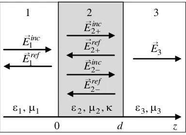
whereεand μare dielectric permittivity and magnetic permeability, and κis the chirality parameter. Let us consider the case of normal propagation of plane electromagnetic waves through the layer of chiral medium with thickness d(Figure 1).
In Figure 1, layers 1 and 3 are represented by non-chiral medium with constitutive parametersε1,
μ1 and ε3,μ3. Layer 2 is represented by a chiral medium with constitutive parametersε2,μ2 andκ.
0 d
1 1,μ
ε ε2,μ2,κ ε3 μ3
3 E inc E1 ref E1 inc E2+
ref
E2+
inc E2− ref E2−
3 2 1 z → → → → → → → ,
Figure 1. The geometry of the problem.
Let the incident wave with the amplitude of E1 be linearly polarized along the x axis. In chiral
medium 2, there are two eigen waves with right (+) and left (−) circular polarization [10, 11].
To find the unknown wave amplitudes for the incident (index “inc”) and reflected (index “ref”) electromagnetic field E1refx , E1refy , E2incx+, E2incx−, E2refx+, E2refx−, E3x, E3y we use the boundary conditions
of equality of the tangential component of the electric and magnetic field intensities at the chiral layer boundaries:
{Ex(z= 0;d)}= 0, {Ey(z= 0;d)}= 0,
{Hx(z= 0;d)}= 0, {Hy(z= 0;d)}= 0.
(3)
Thus, the expressions related to the tangential components of the electromagnetic fields on the opposite boundaries of the chiral layer are as follows:
⎛ ⎜ ⎜ ⎝
Ex(d)
Ey(d)
Hx(d)
Hy(d) ⎞ ⎟ ⎟ ⎠=M
⎛ ⎜ ⎜ ⎝
Ex(0)
Ey(0)
Hx(0)
Hy(0) ⎞ ⎟ ⎟
where elements of the matrixM are as follows:
M =
⎛ ⎜ ⎝
M11 M12 M13 M14
M21 M22 M23 M24
M31 M32 M33 M34
M41 M42 M43 M44
⎞ ⎟
⎠, (5)
M11 =
1 4
eik2+d+eik2−d+e−ik2+d+e−ik2−d = cos(k2d) cos(k0κ d),
M12 = −i
4
eik2+d−eik2−d−e−ik2+d+e−ik2−d = cos(k2d) sin(k0κ d),
M13 = i
4Z2
eik2+d−eik2−d+e−ik2+d−e−ik2−d =−i Z
2sin(k2d) sin(k0κ d),
M14 =
1 4Z2
eik2+d+eik2−d−e−ik2+d−e−ik2−d =i Z2sin(k2d) cos(k0κ d),
M21 = −M34=M43=−M12, M23 =−M14, M22=M33=M44=M11,
M24 = M13, M31=M42=−M13Z2−2, M32=−M41=−M14Z2−2,
Z2 =
μ2/ε2 is the characteristic impedance in medium 2, and k2± = k0(√ε2μ2 ± κ) are the
propagation constants for waves with right (+) and left (−) circular polarizations in medium 2 and
k2 =k0n2 =k0(√ε2μ2).
We find the amplitudes of the electromagnetic field tangential components in media 1 and 3:
E1refx =−E1
(M11+Z1−1M14)−Z3(M41+Z1−1M44)
(M11−Z1−1M14)−Z3(M41−Z1−1M44)
,
E1refy = 0,
E3x = (E1(M11+Z1−1M14) +E1refx (M11−Z1−1M14))e−ik3d,
E3y = (E1(M21+Z1−1M24) +E1refx (M21−Z1−1M24))e−ik3d,
(6)
where Z1 =
μ1/ε1 and Z3 =
μ3/ε3 are the characteristic impedance in media 1 and 3, and
k3 =k0n3 =k0√ε3μ3 are the propagation constant in medium 3.
To find the power transmission and reflection coefficients of electromagnetic waves through the chiral layer, we use the expression for energy flux density [12]:
S = (c/(8π))Re
E ×H∗
. (7)
Expressions for the power transmission T and reflection R coefficient are as follows:
T =Sztr
Szinc,
R=Szref
Szinc,
(8)
where Sinc
z ,Szref, Sztr are normal components of the energy flux density for the incident, reflected and
transmitted waves correspondingly. Analytic expressions for these components are as follows:
Strz = (c/(8π Z3))
|E3x|2+|E3y|2 ,
Szref = (c/(8π Z1))E1refx
2
,
Szinc= (c/(8π Z1))E12.
(9)
Note that as expected for non-absorbing chiral medium (ε2 = 0, μ2 = 0, κ = 0), the relation
T +R = 1 is satisfied. Besides one more important outcome should be from these expressions: the power transmission T and reflection R coefficients are independent of the chirality parameter.
Now in accordance to the aim of our study let us find the rotation angle of the polarization plane
θ for the linearly polarized electromagnetic wave as the ratio of the transmitted wave electromagnetic field tangential components in medium 3 [6, 9, 10]:
3. THEORETICAL STUDY OF THE BAND STRUCTURE OF SPECTRUM OF ELECTROMAGNETIC WAVES PROPAGATED IN THE PERIODIC LAYERED CHIRAL MEDIA
Note that expressions (6) are suitable for the determination of transmitted and reflected waves of the electromagnetic field through the layered structure consisting of m chiral layers. Moreover, the propagation matrix M equals the product of the propagation matrices for single chiral layers, (i= 1, . . . , m):
M =MmMm−1. . . M1, (11)
whereMiare propagation matrices of single chiral layers with thicknessesdiand constitutive parameters
εi,μi, κi. Here, in expressions (6) value d =dm+dm−1 +. . .+d1 is the total thickness of all layers.
Matrix elements are calculated using formulas (5) with the following substitutions: k2 → k0(√εiμi),
Z2 →
μi/εi,d→di,κ →κi.
The rotation angle of the polarization plane for the structure consisting ofmchiral layers is defined as a sum of the rotation angles of the polarization plane for each chiral layer as:
θ=−k0
κ1d1+κ2d2+. . .+κmdm
. (12)
Thus, it is possible to calculate the effective constitutive parameters and polarization characteristics of layered chiral structure using the transmission and reflection coefficients of electromagnetic waves and with the help of technique described in [13].
For the periodic structure consisting of m unit cells, each of which contains two chiral layers, and the resulting propagation matrix is as follows:
Mm = (M2M1)m, (13)
whereM1 andM2 are propagation matrix for chiral layers of the unit cell.
We calculate the transmission (solid line) and reflection coefficients (dashed line) of electromagnetic waves for a periodic structure consisting of m = 5 unit cells (Figure 2). Let assume d1 = 1.5 mm,
d2 = 2.0 mm, ε1 = 3.67, μ1 = 1, κ1 = 0.05, ε2 = 1, μ2 = 1, κ2 = 0. As can be seen from Figure 2,
there are 4 specific areas (for the given parameters), corresponding to forbidden bands for finite periodic structure under study on the dependenceT(ω).
0.0 0.2 0.4 0.6 0.8 1.0
0.0 0.2 0.4 0.6 0.8 1.0
T,
R
ω∗10−12, s−1
Figure 2. Transmission and reflection coefficients of electromagnetic waves for chiral periodic structure with 5 elementary cells.
In order to determine the boundaries of forbidden bands in the transmission coefficient spectrum, it is necessary to solve the equation that relates the tangential components of the amplitudes of the electric and magnetic fields on the boundaries of the unit cell of the infinite periodic structure (Floquet’s theorem [3, 7]):
M ψ =λψ, (14)
whereM =M2M1 is the propagation matrix of the periodic structure unit cell,ψthe vector consisting
Calculating the determinant |M−Iλ| = 0 and grouping the factors relative to λ, we obtain an equation of the fourth degree:
λ4+a3λ3+a2λ2+a1λ+a0 = 0, (15)
where
a0 = |M|= 1, a1 =a3 =−2(M11+M33),
a2 = M112 +M122 +M332 +M342 −2(M13M31−M14M32) + 4M11M33.
Because ofa1 =a3, Equation (15) can be written as a product of two quadratic equations:
(λ2+q1λ+ 1)(λ2+q2λ+ 1) =λ4+ (q1+q2)λ3+ (q1q2+ 2)λ2+ (q1+q2)λ+ 1 = 0, (16)
From (16) we find the relation between the parameters q1,q2 with parameters a1,a2 [7, 14] as:
q1,2=a1/2±
(a1/2)2+ 2−a2. (17)
By solving Equation (15), we obtain two pairs of roots:
λ1,2 =−q1/2±
(q1/2)2−1,
λ3,4 =−q2/2±
(q2/2)2−1.
(18)
We group the solutions of Equation (16) so thatλ1=λ∗2 =eikb1dandλ3 =λ∗4 =eikb2d, whered =d1+d2
is the thickness of the unit cell, andkb1andkb2 are Bloch wave numbers [3]. Then we have the following
relations:
cos(kb1,2d) =−q1,2/2. (19)
Bloch wave numbers are real in the propagation band and complex numbers in the forbidden band. Let rewrite expression (19) as follows:
cos(kb1,2d) = cos((arccosD)∓θ), (20)
where
D= cos(k0n1d1) cos(k0n2d2)−((Z12+Z22)/(2Z1Z2)) sin(k0n1d1) sin(k0n2d2), θ=−k0(d1κ1+d2κ2).
The expression for D determines the Bloch wave number for the non-chiral layered periodic structures with the same values of n1 = √ε1μ1, n2 = √ε2μ2, Z1 =
μ1/ε1, Z2 =
μ2/ε2. The
expression for θdefines the rotation angle of the polarization plane for the unit cell of layered periodic chiral structure. When|D|>1, the value of arccosDbecomes complex, which corresponds to the band gap. When |D| ≤1, the value of arccosD is real. At the same frequencies we have the allowed band. Thus, the boundaries of the forbidden bands are defined by the condition |D| = 1. Note that this condition does not depend on the chirality parameter of the layers in the structure under study.
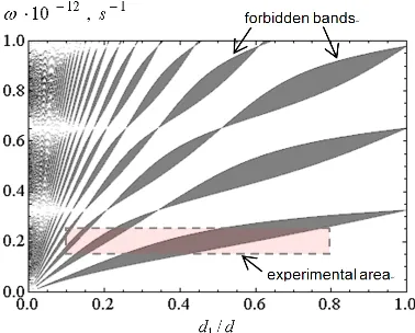
We study the dependence of the boundaries of the forbidden bands for chiral periodic structure as function ofd1/dration for fixedd1= 1.5 mm (Figure 3). The positions of the boundaries are determined
from the condition |D|= 1. The areas shaded in gray correspond to the forbidden bands of the chiral periodic structure.
In Figure 3, we show that about certain relations between the parameters of the chiral layered periodic structure, the width of the forbidden bands tends to zero [15]. This occurs when thicknesses
d1 andd2 equal the integer numbers of half wavelengths. In this case, we have the following conditions:
k0n1d1 =m1π,
k0n2d2 =m2π, (21)
wherem1, m2= 1, 2, 3, . . .are positive integers. Excluding the frequency from Equation (21), we find
the following relation for thicknessesd1 and d2:
d1
d2
= m1
m2
n2
n1.
(22)
The frequencies at which the forbidden bands have zero widths are defined as follows:
ωm1,m2 =cπ(m1n2+m2n1)/(d n1n2). (23)
Figure 3. Dependence of forbidden zones boundaries of ratio of the chiral layer thickness to the thickness of the unit cell of the chiral periodic structure. The square area bounded by the dashed line is the area for experimental study.
4. EXPERIMENTAL STUDY OF THE BAND STRUCTURE OF THE SPECTRUM OF LAYERED PERIODIC CHIRAL MEDIUM
The experimental setup for studying the spectral and polarization characteristics of layered chiral media is shown in Figure 4(a). The structure under study is placed between the transmitting and receiving rectangular horns, which are fitted to the Vector Network Analyzer Agilent N5230A.
(a) (b)
Figure 4. (a) The experimental setup for the study of chiral layered structures; (b) The chiral structure under study.
The horns are located on the same axis passing normally to the structure through its center at a distance about ten wavelengths from the structure. If necessary, the phase-correction lenses can be placed close to the horns, to make the wave front more flat. Receiving horn can be rotated around its axis. S21andS11 parameters are registered in the frequency range 22–40 GHz. The accuracy of theS21
parameter measurement is not worse than 0.5 dB. The experimental technique is described in details in [13, 16].
Investigation of the spectrum band structure was carry out using the structure (Figure 4(b)) formed by seven chiral layers, consisting of two-periodic arrays of chiral elements separated with air gaps. The chiral layers were etched on the foil side of fiberglass by photolithography.
The chiral elements were made in the form of rosettes with the following parameters: period
In order to determine the chirality parameter, the frequency dependences of the rotation angle of the polarization plane of the transmitted wave for a single chiral layer were obtained, first of all. For this, at a fixed frequency the receiving horn was rotated on the angle when the transmitted signal reaches maximum amplitude. This angle corresponds to the rotation angle of the polarization plane of the transmitted waveθ. During the experiment, it was found that in our frequency rangeθangle does not exceed absolute value 2◦. Nonzero rotation angle of the polarization plane of a single chiral layer can be explained by the finite thickness of the metallic elements and the dielectric substrate presence. Then the effective chirality parameter for the single layer was calculated by formula (10):
κ1=− θc
ωd1,
(24)
where d1 = 1.5 mm is the thickness of the chiral layer. The maximum value of the effective chirality
parameter in our frequency range does not exceed absolute value of 0.05. Permittivity and permeability of a single chiral layer were taken the same as for its substrate material. Such a chiral layer simulates the chiral isotropic layer of the same thickness, because it has the same rotation angle of polarization plane of the transmitted wave. Also, the subsequent layers of the chiral structure are located sufficiently far from each other. Therefore, the investigated structure can be considered as a structure with isotropic chiral layers.
The dependence of bandgaps boundaries for the given chiral periodic structure on the ratio of the chiral layer thickness d1 to the unit cell thickness d has been obtained experimentally (Figure 5) for
the area bounded by the dashed line in theoretical graph Figure 3. We take the following values of the parameters for the chiral layers: d1 = 1.5 mm,ε1 = 3.67, μ1= 1, κ1 = 0.05. The parameters of the air
gap with variable thickness d2 between chiral layers we take as follows: ε2 = 1, μ2 = 1, κ2 = 0.
As seen in Figure 5, there is quite good qualitative agreement between the theoretically calculated and experimentally defined boundaries of the forbidden zones for the finite periodically layered chiral structure under study. A certain divergence between the forbidden zones boundaries frequencies (less than 5%) should be assigned to non-ideal matching between circuit elements, as well as probably to some non-correctness of chiral layers constitutive parameters values, used for the calculation.
Thus, our experimental study shows the possibility of determining the effective constitutive parameters of layered periodic chiral media using with help of technique described in [13].
1 12,
10− −
⋅ s
ω
d d1/
experiment theory
Figure 5. Comparison of experimental and theoretical dependences of the forbidden zones boundaries versus the ratio of the thickness of chiral layer to the thickness of unit cell of the chiral periodic structure.
5. CONCLUSIONS
the forbidden bands of the periodic chiral medium whose unit cell consists of two planar chiral layers were defined. It is shown that these boundaries do not depend on the chirality parameter of the layers within the structure. It was found that for certain values of chiral layers thicknesses the width of band gap becomes zero. A distinctive feature of layered chiral medium is the appearance of the additional rotation angle of the polarization plane of the transmitted wave in contrast to the conventional non-chiral layered medium.
The transmission and reflection coefficients of plane electromagnetic waves through a finite periodically layered chiral structure were determined experimentally. A good agreement between the experimental results and theoretical studies of the band spectrum of the periodical layered chiral structures was obtained. The studies presented above allow us to calculate the effective constitutive parameters of layered chiral media in order to design the artificial metamaterials with predetermined features.
ACKNOWLEDGMENT
Authors are grateful to Prof. V. R. Tuz and Dr. O. V. Kostylova for fruitful discussions, V. P. Ruban for help in preparing the research samples.
REFERENCES
1. Brekhovskikh, L. M.,Waves in Layered Media, Academic Press, San Diego, 1960. 2. Yariv, A. and P. Yeh, Optical Waves in Crystals, Wiley, New York, 1990.
3. Tuz, V. R., M. Yu. Vidil, and S. L. Prosvirnin, “Polarization transformations by a magneto-photonic layered structure in the vicinity of a ferromagnetic resonance,” Journal of Optics, Vol. 12, No. 9, 095102, 2010.
4. Girich, A. A., S. Yu. Polevoy, S. I. Tarapov, A. M. Merzlikin, A. B. Granovsky, and D. P. Belozorov, “Experimental study of the Faraday effect in 1D-photonic crystal in millimeter waveband,” Solid State Phenomena, Vol. 190, 365–368, 2012.
5. Tarapov, S. I. and D. P. Belozorov, “Microwaves in dispersive magnetic composite media (review article),” Low Temperature Physics, Vol. 38, No. 7, 766–792, 2012.
6. Lekner, J., “Optical properties of isotropic chiral media,” Pure Appl. Opt., Vol. 5, 417–443, 1996. 7. Tuz, V. R. and V. B. Kazanskiy, “Depolarization properties of a periodic sequence of chiral and
material layers,”J. Opt. Soc. Am. A, Vol. 25, No. 11, 2704–2709, 2008.
8. Tuz, V. R. and C.-W. Qiu, “Semi-infinite chiral nihility photonics: Parametric dependence, wave tunneling and rejection,”Progress In Electromagnetics Research, Vol. 103, 139–152, 2010.
9. Ivanov, O. V., Electromagnetic Wave Propagation in Anisotropic and Bianisotropic Layered Structures, UlSTU, Ulyanovsk, 2010 (in Russian).
10. Lindell, I. V., A. H. Sihvola, S. A. Tretyakov, and A. J. Viitanen,Electromagnetic Waves in Chiral and Bi-Isotropic Media, Artech House, Boston-London, 1994.
11. Katsenelenbaum, B. Z., E. N. Korshunova, A. N. Sivov, and A. D. Shatrov, “Chiral electromagnetic objects,” Phys. Usp.,Vol. 40, No. 11, 1149–1160, 1997.
12. Landau, L. D. and E. M. Lifshitz, The Classical Theory of Fields,Nauka, Moscow, 1988.
13. Polevoy, S. Y., “Experimental determination of constitutive parameters of the chiral media in the millimeter wavelength range (in Russian),”Radiophysics and Electronics, Vol. 4(18), No. 4, 27–33, 2013.
14. Bulgakov, A. A. and V. K. Kononenko, “Dispersion properties of cyclotron waves in periodic semiconductor-insulator structures,”Technical Physics,Vol. 49, No. 10, 1313–1318, 2004.
15. Vinogradov, A. P., A. V. Dorofeenko, A. M. Merzlikin, and A. A. Lisyansky, “Surface states in photonic crystals,” Phys. Usp.,Vol. 53, No. 3, 243–256, 2010.