Power Control in Ac Isolated Micro Grids Using Fuzzy Controller
for Improved Performance
P.Sravya Rao , P.Shiva Kumar , Dr.P.Sridhar
1M-Tech Student Scholar Department of Power Electronics & Electrical Drives, Institute of Aeronautical Engineering (IARE) , Dundigal,
Hyderabad; Telangana, India
2Assistant Professor Department of Power Electronics & Electrical Drives, Institute of Aeronautical Engineering (IARE) , Dundigal,
Hyderabad; Telangana, India
3 Department of Power Electronics & Electrical Drives, ( H.O.D ) Institute of Aeronautical Engineering (IARE) , Dundigal, Hyderabad;
Telangana, India
Email: [email protected] , Email:[email protected] , Email:[email protected]
Abstract- The enabling of ac micro grids in distribution networks allows delivering distributed power and providing grid support services during regular operation of the grid, as well as powering isolated islands in case of faults and contingencies, thus increasing the performance and reliability of the electrical system. This paper proposes an alternative strategy to control the generated power within an isolated ac micro grid with distributed RES. The proposal is to control the terminal voltage of the existing battery banks below or equal its maximum allowable value. In this particular study, the power system consists of a power electronic converter supplied by a battery bank, which is used to form the ac grid (grid former converter), an energy source based on a wind turbine with its respective power electronic converter (grid supplier converter), and the power consumers (loads). The main objective of this proposed strategy is to control the state of charge of the battery bank limiting the voltage on its terminals by controlling the power generated by the energy sources. This is done without using dump loads or any physical communication among the power electronic converters or the individual energy source controllers. The electrical frequency of the micro grid is used to inform the power sources and their respective converters about the amount of power that they need to generate in order to maintain the battery-bank charging voltage below or equal its maximum allowable limit.. The Proposed concept is implemented by fuzzy controlled logic using mat lab/simulation link software.
Index Terms—Battery banks, isolated micro grids, parallel inverters, power control, renewable energy sources (RESs), state of charge (SOC).
I. INTRODUCTION
Micro grids are becoming popular in distribution systems because they can improve the power quality and reliability of power supplies and reduce the environmental impact. Micro grid operation can be classified into two modes: grid-connected and islanded modes. In general,
micro grids are comprised of distributed energy resources (DERs) including renewable energy sources, distributed energy storage systems (ESSs), and local loads [1–3]. However, the use of renewable energy sources such as wind and solar power in micro grids causes power flow variations owing to uncertainties in their power outputs. These variations should be reduced to meet power-quality requirements [4,5]. This study focuses on handling the problems that are introduced by wind power. To compensate for fluctuations in wind power, various ESSs have been implemented in micro grids. Short-term ESSs such as superconducting magnetic energy storage (SMES) systems [6], electrical double-layer capacitors (EDLCs) [7], and flywheel energy storage systems (FESSs) as well as long-term ESSs such as battery energy storage systems (BESSs) [8-9] are applied to micro grid control. ESSs can also be used to control the power flow at point of common coupling in the grid-connected mode as well as to regulate the frequency and voltage of a micro grid in the islanded mode. Among these ESSs, BESSs have been implemented widely owing to their versatility, high energy density, and efficiency. Moreover, their cost has decreased whereas their performance and lifetime has increased.
In practice, BESSs with high performance such as smooth and fast dynamic response during charging and discharging are required for micro grid control. This performance depends on the control performance of the power electronic converter. Proportional-integral (PI) control is a practical and popular control technique for BESS control systems. However, PI control might show unsatisfactory results for nonlinear and discontinuous systems [10].
successful integration of DG power sources requires the single-direction grid architecture of the past transition to a smarter and more agile bi-directional grid [11]. As DGs continue to gain traction in the electrical market, new thinking and new strategies around power generation, distribution and consumption will continue to emerge. One of the increasingly common tactics for merging DGs into the larger electrical grid is a new twist on an old electrical architecture known as the micro grid. Micro grids are areas of the grid that can operate as part of the larger macro grid or operate autonomously as a standalone system. The micro grid systems help facilitate the integration of DG assets into the larger electrical grid. Further, when properly implemented, micro grids can unlock a wide array of stacked values for grid operators and electrical consumers [12-13].
II. SYSTEM DESCRIPTION
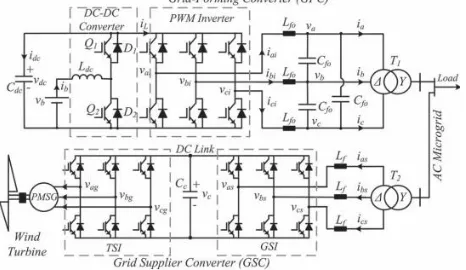
Fig. 1 illustrates the simplified diagram of a stand-alone micro grid used to explain the control strategy proposed in this paper. It consists of a GFC, a GSC, and a battery bank. The renewable energy source, in this particular study, is a variable speed wind turbine coupled to a permanent-magnet synchronous generator (PMSG). Depending on the system size, other energy sources and other storage energy systems can be distributed along the micro grid. The simplicity of this system is useful to show the feasibility of the proposed control strategy without losing generality.
Fig. 1. Simplified diagram of the studied micro grid. The GFC is a bidirectional converter formed by a pulse width modulation (PWM) three-phase inverter and a dc– dc converter that works in a buck mode when the battery bank is undercharge or in a boost mode when it is under discharge. The PWM inverter controls the magnitude and frequency of the micro grid
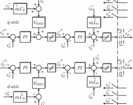
Fig. 2. Block diagram of LC filter implemented in a synchronous reference frame.
Voltage, while the dc–dc buck or boost converter is used to control the voltage at the dc bus capacitor (Cdc) which is the dc bus voltage as well as the charging and discharging of the battery bank.
The GSC is used to control the power generated by the renewable energy source. In this particular example, the converter is formed by a conventional back-to-back topology [12]. It has a grid-side PWM inverter (GSI) and a wind turbine-side PWM inverter (TSI). The GSI is used to control the dc-link voltage of the back-to-back topology, and the TSI is used to control the power generated by the wind turbine based on a maximum power point tracker (MPPT) algorithm.
III. GRID FORMER CONVERTER
In this figure, “∧” denotes estimated parameters, and GDID1 is the transfer function used to decouple at the sample instants the effect of the disturbances due to the load currents ieqe ied and the cross-coupling due to vq e and vd e. ZOH means zero-order hold (latch). Fundamentally, the current on the inductance Lf0
Fig. 3. Block diagram of the micro grid voltage controller. is controlled in order to regulate the voltage on the capacitanceCf0, independently whether the power flux is from the PWMinverter to the micro grid or vice versa. The voltage reference values for the voltage controllers can be constant, generally equal to the nominal value of the micro grid voltage, or can be calculated based on a droop control strategy. In this paper, the voltage reference was fixed in 220 V(rms line voltage in the delta side of T1).
B. Control of the Bidirectional DC–DC Converter The dc–dc converter (in GFC) is used to control the voltage in the capacitor Cdc. The action of the controller of thedc–dc converter can be considered equivalent to connecting a controlled voltage source, with mean value Vct, between the xy terminals of the converter circuit, as shown in Fig. 4(a) and (b).If the losses in the converter are not considered, the voltage on Cdc depends only on the difference between the power at the battery bank terminals (Pb) and (Pinv) which is the power at the terminals of the delta side of the isolation transformer T1,which is positive when the power flux is from the inverter to the grid and negative on the contrary. This is shown in Fig. 4(c).Therefore, the dynamic equation for vdc can be written as in(1), where wdc is an auxiliary variable defined by wdc = v2dc
(1) From (1) and Fig. 4, the dc bus voltage controller of the GFC can be designed with an inner current loop to control
the battery bank current (ib) and an outer voltage loop to control the voltage over the capacitor Cdc, as illustrated in Fig. 6.
Fig. 4. DC–DC converter average model: (a) Original circuit, (b) equivalent average circuit of inductor and battery bank, and (c) average
model of the bus dc.
Fig. 5. Block diagram of the voltage controller of the dc–dc converter.
Fig. 6. Block diagram of the commands for the switches of the dc–dc converter.
GDID2 is used to decouple the power disturbance from the output of the inverter over the dc bus voltage. The output of the voltage controller (Vct) is the reference value for the PWM block used to generate the control signal forQ1 or Q2 switches, as shown in Fig. 6 [4].In Fig. 6, when Pinv is positive, the battery bank supplies the load, and the dc–dc converter functions on the boost mode using the Q2 switch and D1 diode. On the other hand, when Pinv is negative, the dc–dc converter functions on the buck mode using the Q1 switch and D2 diode.
A. Control of the Injected Current in the Microgrid and the Voltage at the DC Bus
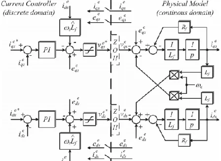
In this paper, the GSI of the GSC (see Fig. 1) is used to control the dc bus voltage of the back-to-back topology. This controller uses an inner current loop to control the injected current in the micro grid. The current controller is implemented in a dq synchronous reference frame aligned with the micro grid positive sequence voltage vector. The converter variable synchronization is done by using a synchronous phase-locked loop (PLL) that has a second-order resonant filter tuned for the fundamental frequency of the micro grid.
Fig. 7. Block diagram of the control of the injected current in the micro grid by the GSC.
Fig. 8. Block diagram of the dc bus voltage controller for the GSC. This PLL also has a module to extract the instantaneous positive and negative symmetrical components of the voltage of the micro grid [13]. The PLL was tuned based on its small signal analysis model for a bandwidth of 100 Hz. The block diagram of the current controller together with the filter (Lf) model in a synchronous reference frame is illustrated in Fig. 8, where Rf is the equivalent series resistance of the inductor Lf, ie qs and ie ds are the currents in the delta side of transformer T2, and eeqs and eeds are the dq axis components of the micro grid voltage. The adopted current direction references are the same as those shown in Fig. 1.If the losses in the GSI and in the
inductor Lf are neglected, the variation of the energy stored in the capacitor Cc is equal to the difference between the active power received from themicrogrid (Ps) and the active power generated by the wind turbine (Pg). Using the convention of Fig. 2, this can be expressed as in
(2) For a dq synchronous reference frame aligned with themicrogrid voltage vector, it follows that ee ds = 0. Therefore, sis equal to (3/2) Esie qs, with Es being the magnitude of the phase voltage, considered constant in this application. By defining Kc equal to (3/2Es), the dynamic equation for the capacitor Cc is presented in
(3) The block diagram for the dc bus voltage controller is illustrated in Fig. 8. GDID3 is the transfer function used to decouple at the sample instants the effect of the disturbances due to Pg, and τf is the time constant Lf /Rf. The output of the voltage controller is the reference current (ie qs ∗) for the inner current loop.
V. PROPOSED STRATEGY TO CONTROL THEGENERATED POWER IN THE MICROGRID In stand-alone and distributed renewable energy systems, there is no commercial or conventional grid to absorb any surplus power generated internally in the micro grid. Therefore, the generated power needs to be controlled when the load power is less than the amount of power that could be generated by the energy sources. This is necessary to keep the energy balance in the micro grid under control and to keep the battery bank voltage below or equal its maximum allowable value. This is necessary since voltages higher than the gasification voltage can decrease the life span of batteries or even damage them irreversibly [17].In the proposed control strategy, the GFC verifies the battery bank voltage to know if it reached the maximum allowed charging voltage and, if so, change the micro grid frequency to inform the other sources that they must reduce their generated power. Based on the micro grid frequency, the control systems of the power generation sources connected to the micro grid decide whether to restrict the power generated by each of them.
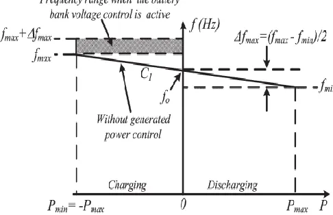
cannot be neglected [7]. The frequency value is calculated by (8), where kp is the slope constant of the line C1.On this situation, there are no restrictions about the amount of power that can be generated, and the existing renewable energy sources can function on their maximum power point. Obviously, this is true only if the battery bank has been designed with sufficient capacity to absorb all the power that the renewable sources can produce at a given instant
On the other hand, if the maximum voltage of the battery bank is reached, the micro grid frequency is imposed to be always higher than the value fmax, which is the maximum frequency of operation of the conventional droop control strategy. This is illustrated by the hatched area in Fig.9. Now, the value of the frequency (f) is a variable that changes dynamically
Fig. 9. Frequency versus power in the GFC based on the proposed power control.
Fig. 10. Block diagram of the frequency control at the GFC. With the terminal voltage of the battery bank (vb), the power generated internally in the micro grid (Pg), and the power of the GFC (Pinv). This can be expressed by (9). As the calculation of the frequency depends on the dynamics of the battery bank voltage controller, its relationship with the power (Pinv) does not follow a
well-defined algebraic equation as, for example, a straight line. Therefore, Fig. 3 shows only an illustration that the frequency can assume any value between fmax and fmax +Δfmax. In this operating condition, it is necessary to restrict the amount of power that can be generated by renewable sources; otherwise, the integrity of the battery bank is at risk. The amount of power that needs to be reduced from the maximum power that each source is able to produce at every moment has a direct relation to the frequency difference Δf = f − fmax. The values of fo and ±Δfmax adopted in this work are 60 Hz and ± 0.60 Hz so that the frequency range of the micro grid is between 59.4 Hz (fmin) and 61.2 Hz (fmax + Δfmax).
A. Implementation of the Proposed Strategy in the GFC The control of the battery bank voltage, in order to ensure its integrity, was implemented as shown in Fig. 10. While the output of the hysteresis loop is zero, the value of the frequency reference is fe ∗ = f1. On the other hand, while the output of the hysteresis loop is one, a proportional and integral (PI) controllers used to regulate the terminal voltage of the battery bank equal or below its maximum allowed value (Vbmax). The output of
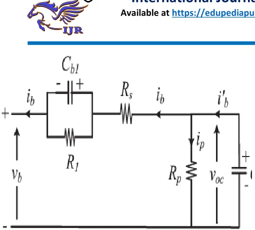
Fig. 12. Lead–acid battery equivalent circuit.
This controller is the increment of frequency (Δf) that must be added to the value fmax to form the new micro grid frequency reference value (fe ∗ = f2 = fmax + Δf). The value of Δf is proportional to the amount of power that must be decremented from the generated power in order to control the battery bank terminal voltage. The low-pass filter with a 1-Hz bandwidth shown in Fig. 9 is used to avoid sudden variations in frequency due the hysteresis loop.
B. Implementation of the Proposed Strategy in the GSC The grid frequency is measured by the GSC and if its value is higher than fmax, it means that the voltage of the battery bank is higher than its maximum allowed value. For the particular case where the renewable energy source is a wind turbine, the GSC power controller decrements the current reference i∗ q, originally calculated by (7), which is now calculated by (10), where Kfis a constant which serves to match the rated power of the GFC with the rated power of the wind turbine. The block diagram of this control action is presented in Fig. 11.
As the reference current is now determined by (10), the operating points of the wind turbine-generator set follow the dashed curve indicated by Tg in Fig. 8. This implies a reduction in the generator torque, which causes a reduction in power that is produced by the wind turbine keeping regulated the terminal voltage of the battery bank.
C. Tuning of the Battery Bank Terminal Voltage Controller
The tuning of the PI controller shown in Fig. 10 takes into account the dynamic of the battery bank. One possible model for lead–acid batteries is shown in Fig. 12. In this figure, voc is the battery open circuit voltage, Rs is the equivalent series internal resistance, R1 and Cb1 are used
to model the over- or under voltage that happens when the battery is charging or discharging, Rp is the resistance due the natural losses, and Cbo models the battery capacity to storage energy. Normally, the natural losses occur very slowly, so the effect of Rp can be disregarded for the purpose of this work.
VI Proposed work: A IMPORTANCE OF FUZZY LOGIC
Fuzzy logic is all about the relative importance of precision: use as Fuzzy Logic Toolbox software with MATLAB technical computing software as a tool for solving problems with fuzzy logic. Fuzzy logic is a fascinating area of research because it does a good job of trading off between significance and precision something that humans have been managing for a very long time. In this sense, fuzzy logic is both old and new because, although the modern and methodical science of fuzzy logic is still young, the concept of fuzzy logic relies on age-old skills of human reasoning.
B USAGE OF FUZZY LOGIC
Fuzzy logic is a convenient way to map an input space to an output space. Mapping input to output is the starting point for everything. Consider the following examples:
With information about how good your service was at a restaurant, a fuzzy logic system can tell you what the tip should be.
With your specification of how hot you want the water, a fuzzy logic system can adjust the faucet valve to the right setting.
With information about how far away the subject of your photograph is, a fuzzy logic system can focus the lens for you.
With information about how fast the car is going and how hard the motor is working, a fuzzy logic system can shift gears for you.
To determine the appropriate amount of tip requires mapping inputs to the appropriate outputs. Between the input and the output, the preceding figure shows a black box that can contain any number of things: fuzzy systems, linear systems, expert systems, neural networks, differential equations, interpolated multidimensional lookup tables, or even a spiritual advisor, just to name a few of the possible options. Clearly the list could go on and on.
Of the dozens of ways to make the black box work, it turns out that fuzzy is often the very best way. As Lotfi Zadeh, who is considered to be the father of fuzzy logic, once remarked: "In almost every case you can build the same product without fuzzy logic, but fuzzy is faster and cheaper".
Fuzzy logic is not a cure-all. When should you not use fuzzy logic? The safest statement is the first one made in this introduction: fuzzy logic is a convenient way to map an input space to an output space. Fuzzy logic is the codification of common sense — use common sense when you implement it and which will probably make the right decision. Many controllers, for example, do a fine job without using fuzzy logic. However, it take the time to become familiar with fuzzy logic, it can be a very powerful tool for dealing quickly and efficiently with imprecision and nonlinearity.
D The Fuzzy Logic Concept
Fuzzy logic arose from a desire to incorporate logical reasoning and the intuitive decision making of an expert operator into an automated system. The aim is to make decisions based on a number of learned or predefined rules, rather than numerical calculations. Fuzzy logic incorporates a rule-base structure in attempting to make decisions. However, before the rule-base can be used, the input data should be represented in such a way as to retain meaning, while still allowing for manipulation. Fuzzy logic is an aggregation of rules, based on the input state variables condition with a corresponding desired output. A mechanism must exist to decide on which output, or combination of different outputs, will be used since each rule could conceivably result in a different output action.
Fuzzy logic can be viewed as an alternative form of input=output mapping. Consider the input premise, x, and a particular qualification of the input x represented by Ai. Additionally, the corresponding output, y, can be qualified by expression Ci . Thus, a fuzzy logic representation of the relationship between the input x and the output y could be described by the following:
R1: IF x is A1 THEN y is C1 R2: IF x is A2 THEN y is C2
. . . . . . . . . Rn: IF x is An THEN y is Cn
where x is the input (state variable), y is the output of the system, Ai are the different fuzzy variables used to classify the input x and Ci are the different fuzzy variables used to classify
the output y. The fuzzy rule representation is linguistically based .
Thus, the input x is a linguistic variable that corresponds to the state variable under consideration. Furthermore, the elements Ai are fuzzy variables that describe the input x. Correspondingly, the elements Ci are the fuzzy variables used to describe the output y. In fuzzy logic control, the term ‘‘linguistic variable’’ refers to whatever state variables the system designer is interested
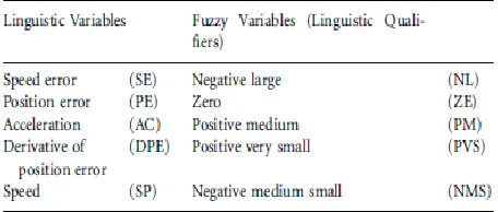
in . Linguistic variables that are often used in control applications include Speed, Speed Error, Position, and Derivative of Position Error. The fuzzy variable is perhaps better described as a fuzzy linguistic qualifier. Thus the fuzzy qualifier performs classification
(qualification) of the linguistic variables. The fuzzy variables frequently employed include Negative Large, Positive Small and Zero. Several papers in the literature use the term ‘‘fuzzy set’’ instead of ‘‘fuzzy variable’’, however; the concept remains the same. Table 4.1 illustrates the difference between fuzzy variables and linguistic variables. Once the linguistic and fuzzy variables have been specified, the complete inference system can be defined. The fuzzy linguistic universe, U, is defined as the collection of all the fuzzy variables used to describe the linguistic variables .
i.e. the set U for a particular system could be comprised of Negative Small (NS), Zero (ZE) and Positive Small (PS). Thus, in this case the set U is equal to the set of [NS, ZE, PS]. For the system described by , the linguistic universe for the input x would be the set Ux . .A1A2 . . . An.. Similarly,
TABLE 4.1 Fuzzy and linguistic variables
The linguistic universe for the output y would be the set Uy . .CaC2 . . . Cn.
The Fuzzy Inference System (FIS) The basic fuzzy inference system (FIS) can be classified as: Type 1 Fuzzy Input Fuzzy Output (FIFO)
Type 2 Fuzzy Input Crisp Output (FICO)
Type 2 differs from the first in that the crisp output values are predefined and, thus, built into the inference engine of the FIS. In contrast, type 1 produces linguistic outputs. Type 1 is more general than type 2 as it allows redefinition of the response without having to redesign the entire inference engine. One drawback is the additional step required, converting the fuzzy output of the FIS to a crisp output. Developing a FIS and applying it to a control problem involves several steps:
1. Fuzzification
2. Fuzzy rule evaluation (fuzzy inference engine) 3. Defuzzification.
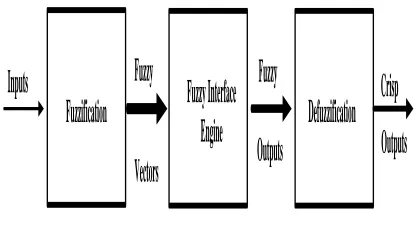
(fuzzification), then the linguistic inputs are related to outputs (fuzzy inference) and, finally, all the different outputs are combined to produce a single output (defuzzification). Figure 4.1 shows a block diagram of the fuzzy inference system.
Inputs
Fuzzification
Defuzzification
Fuzzy
Vectors
Fuzzy
Outputs
Outputs
Crisp
Fuzzy Interface
Engine
Fig .13 Fuzzy inference system. E Fuzzification:
Fuzzy logic uses linguistic variables instead of numerical variables. In a control system, error between reference signal and output signal can be assigned as Negative Big (NB), Negative Medium (NM), Negative Small (NS), Zero (ZE), Positive small (PS), Positive Medium (PM), Positive Big (PB). The triangular membership function is used for fuzzifications. The process of fuzzification convert numerical variable (real number) to a linguistic variable (fuzzy number). Simply the process of converting a numerical variable (real number) convert to a linguistic variable (fuzzy number) is called fuzzification.
F.Defuzzification:
The rules of fuzzy logic controller generate required output in a linguistic variable (Fuzzy Number), according to real world requirements; linguistic variables have to be transformed to crisp output (Real number). This selection of strategy is a compromise between accuracy and computational intensity.
The rules of FLC generate required output in a linguistic variable (Fuzzy Number), according to real world requirements, linguistic variables have to be transformed to crisp output (Real number).
Database: the Database stores the definition of the membership Function required by fuzzifier and defuzzifier.
Rule Base: the elements of this rule base table are determined based on the theory that in the transient state, large errors need coarse control, which requires coarse in-put/output variables; in the steady state, small errors need fine control, which requires fine input/output variables. Based on this the elements of the rule table are obtained as shown in Table 4.2, with’ Vdc’ and ‘Vdc-ref’ as inputs. G FUZZY LOGIC CONTROLLER
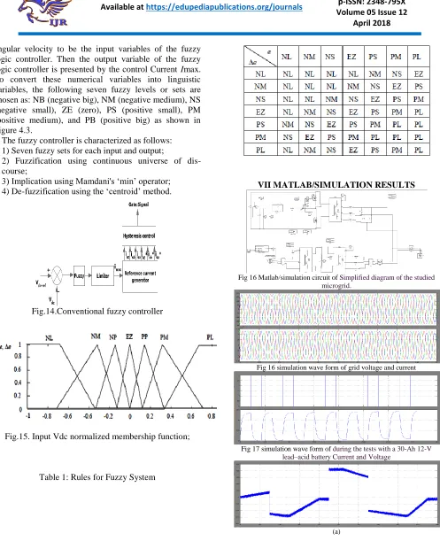
angular velocity to be the input variables of the fuzzy logic controller. Then the output variable of the fuzzy logic controller is presented by the control Current Imax. To convert these numerical variables into linguistic variables, the following seven fuzzy levels or sets are chosen as: NB (negative big), NM (negative medium), NS (negative small), ZE (zero), PS (positive small), PM (positive medium), and PB (positive big) as shown in Figure 4.3.
The fuzzy controller is characterized as follows: 1) Seven fuzzy sets for each input and output;
2) Fuzzification using continuous universe of dis-course;
3) Implication using Mamdani's ‘min’ operator; 4) De-fuzzification using the ‘centroid’ method.
Fig.14.Conventional fuzzy controller
Fig.15. Input Vdc normalized membership function;
Table 1: Rules for Fuzzy System
VII MATLAB/SIMULATION RESULTS
Fig 16 Matlab/simulation circuit of Simplified diagram of the studied microgrid.
Fig 16 simulation wave form of grid voltage and current
Fig 17 simulation wave form of during the tests with a 30-Ah 12-V lead–acid battery Current and Voltage
(b)
(c)
(d)
Fig 18simulation wave form of Operation with a constant wind speed of 9.2 m/s: (a) Power at the GFC terminals, (b) battery bank voltage, (c)
microgrid frequency, and (d) battery current
(a)
(b)
(c)
(d)
Fig 19 simulation wave form of peration with variable wind speed: (a) Power at the GFC terminals, (b) battery bank voltage, (c) microgrid
frequency, and (d) battery current.
(a)
(b)
(c)
(d)
Fig 20 simulation wave form of operation with variable wind speed with fuzzy controller : (a) Power at the GFC terminals, (b) battery bank
voltage, (c) micro grid frequency, and (d) battery current
VIII CONCLUSION
the surplus of generated power in the microgrid. These technical advantages make the proposed strategy a promising tool to increase the viability and reliability of the renewable power generation system installed in isolated and remote communities. Although a wind turbine has been used to demonstrate the validity of the proposed strategy, it is also valid regardless of the power source existing in the isolated microgrid.The proposed
strategy calculates the amount
of power that must be generated at each time by each source in order to keep the balance of energy into the micro grid. In other words, the sum of the generated, consumed, and stored energy must always be zero all the time
REFERENCES
[1].José G. de Matos, Member, IEEE, Felipe S. F. e Silva, Student Member, IEEE, and Luiz A. de S. Ribeiro, Member, IEEE” Power Control in AC Isolated Micro grids With Renewable Energy Sources and Energy Storage Systems” IEEE Transactions On Industrial Electronics, Vol. 62, No. 6, June 2015.
[2] L. A. de S. Ribeiro, O. R. Saavedra, S. L. de Lima, and J. G. de Matos, “Isolated micro-grid with renewable hybrid generation: The case of Lençóis island,” IEEE Trans. Sustain. Energy, vol. 2, no. 1, pp. 1–11, Jan. 2011.
[3] L. A. de S. Ribeiro, O. R. Saavedra, S. L. de Lima, and J. G. de Matos, “Making isolated renewable energy systems more reliable,” Renew. Energy, vol. 45, pp. 221–231, Sep. 2012.
[4] J. G. de Matos, L. A. de S. Ribeiro, and E. C. Gomes, “Power control in ac autonomous and isolated micro grids with renewable energy sources and energy storage systems,” in Proc. IEEE IECON, 2013, pp. 1827–1832.
[5] N. Mendis, K. M. Muttaqi, S. Pereira, and M. N. Uddin, “A novel control strategy for stand-alone operation of a wind dominated RAPS system,” in Proc. IEEE IAS Annu. Meeting, 2011, pp. 1–8.
[6] J. Chen, J. Cheng, C. Gong, and X. Deng, “Energy management and power control for a stand-alone wind energy conversion system,” in Proc. IEEE IECON, 2012, pp. 989–994.
[7] M. J. Erickson and R. H. Lasseter, “Integration of battery storage element in a CERTS microgrid,” in Proc. IEEE ECCE, 2010, pp. 2570– 2577.
[8] J. Rocabert, J. A. Luna, F. Blaabjerg, and P. Rodrígues, “Control of power converters in ac microgrids,” IEEE Trans. Power Electron., vol. 27, no. 11, pp. 4734–4749, Nov. 2012.
[9] C. Jin, P. Wang, J. Xiao, Y. Tang, and F. H. Choo, “Implementation of hierarchical control in dc microgrids,” IEEE Trans. Ind. Electron., vol. 61, no. 8, pp. 4032–4042, Feb. 2014.
[10] X. Lu, K. Sun, J. M. Guerrero, J. C. Vasquez, and L. Huang, “State-ofcharge balance using adaptive droop control for distributed energy storage systems in dc microgrid applications,” IEEE Trans. Ind. Electron., vol. 61, no. 6, pp. 2804–2815, Jun. 2014.
[11] M. A. Abusara, J. M. Guerrero, and S. M. Sharkh, “Line-interactive UPS for microgrids,” IEEE Trans. Ind. Electron., vol. 61, no. 3, pp. 1292–1300, Mar. 2014.
[12] J. M. Guerrero, P. X. Loh, T.-L. Lee, and M. Chandorkar, “Advanced control architectures for intelligent micro grids–Part II: Power quality, energy storage, ac/dc microgrids,” IEEE Trans. Ind. Electron., vol. 60, no. 4, pp. 1263–1270, Apr. 2013.
[13] Z. Chen, J. M. Guerrero, and F. Blaabjerg, “A review of the state of art of power electronics for wind turbines,” IEEE Trans. Power Electron., vol. 24, no. 8, pp. 1859–1875, Aug. 2009.
AUTHOR DETAILS
AUTHOR -1 P.SRAVYARAO M.Tech student scholar
Department Of Power Electronics And Electrical Drives Institute Of Aeronautical Engineering(IARE),Dundigal Hyderabad,Telangana,India
Email:[email protected]
Interested areas:Power electronics and its applications like wind turbines,PV Systems
AUTHOR -2 P.SHIVA KUMAR Assistant Professor
Department Of Electrical&Electronics Engineering, Institute Of Aeronautical Engineering(IARE),Dundigal, Hyderabad,Telangana,India,
Email:[email protected]
AUTHOR -3 DR.P.SRIDHAR Professor(HOD),
Department Of Electrical&Electronics Engineering, Institute Of Aeronautical Engineering(IARE),Dundigal, Hyderabad,Telangana,India,