Clubs-shaped Antenna with Reconfigurable Radiation Pattern
for Wideband Wireless Applications
Hongyun Li and Peng Gao*
Abstract—A clubs-shaped wideband antenna with reconfigurable radiation pattern is proposed. This antenna is composed of two tapered slots of mirror symmetry, embedded with two PIN diodes and fed by a 50 Ω coplanar waveguide (CPW). By controlling states of PIN diodes, two tapered slots can be shut down or opened. Consequently, the proposed antenna works in three radiation modes: one monopole pattern with a simulation frequency band (3.93–5.55 GHz) and two end-fire patterns with an identical band (3.29-6.13 GHz). The antenna is fabricated and tested. Measured results show good agreement with the simulation, which denotes that it is suitable for wideband wireless communication systems.
1. INTRODUCTION
The demand of high quality of wireless communication systems requires higher operating flexibility such as effective switching at different frequencies, patterns and polarizations. Meanwhile, there is also a trend of miniaturization and low cost. A reconfigurable antenna can be designed to be reusable at characteristics such as frequency, radiation pattern and polarization without increase of antennas [1–4], and has been a promising solution to meet these conflicting requirements [5, 6]. Meanwhile, wideband pattern reconfigurable antenna has attracted significant attention for its flexibility and large capacity. Several methods have been adopted in the research of pattern reconfiguration [7–9]. In [7, 8], a few PIN diodes are loaded into parasitic patches, which play the role of directors or reflectors when the diodes’ states change. In [9], controlling off-on states of four PIN diodes to achieve the switch between a tapered slot and a monopole structure results in one end-fire radiation pattern and one omnidirectional pattern. But the antenna has only two radiation modes, which limits its scope of application. To further increase the number of radiation modes, the design of [9] is improved. In this paper, two back-to-back tapered slots, embedded with two diodes placed across the narrow gaps, are combined to achieve a clubs structure with a CPW feeding line connected to the common limb. By controlling states of PIN diodes, three radiation patterns are realized: one monopole pattern with a simulation frequency band of 3.93– 5.55 GHz radiated at Y OZ plane and two end-fire patterns with an identical band of 3.29–6.13 GHz radiated at about Φ = 45 deg and Φ = 135 deg, respectively.
2. ANTENNA DESIGN
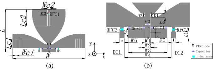
The geometry of the proposed antenna and some details on component configuration are illustrated in Fig. 1. Fig. 1(a) shows the overall size while Fig. 1(b) shows details of the PIN biasing configuration. DC1–DC3 are direct current (DC) biasing pad; RFC1–RFC3 are 18 nH Murata RF choking inductance of 0805 package; C1–C5 are 47 pF DC blocking capacitor of 0603 package. D1 and D2 are PIN diodes. The antenna is designed based on Vivaldi antenna method. First, an exponential curve was created
Received 13 August 2016, Accepted 21 October 2016, Scheduled 12 November 2016
* Corresponding author: Peng Gao (penggao@uestc.edu.cn).
under theXOY coordinate system. Then a patch was formed with the curve’s mirror image by rotating ϕ. Finally, after being duplicated by rotating±90 degrees aroundZ axis and tailored, a clubs-shaped patch is generated. The exponential function is shown as in Eq. (1) while Formulas (2) and (3) give the expressions of c1 andc2 in Formula (1) [10].
y1 = c1·era·x+c2, x∈[x1, x2] (1) c1 = y2−y1
era·x2−era·x1 (2)
c2 = y1·e
ra·x2−y2·era·x1
era·x2−era·x1 (3)
In order to reduce the increment of size in y direction caused by DC3, a slot ofWc2 in width and Lc2 in length is loaded into the common limb, and the DC bias line (DC3) is inserted into the slot. Some comb slots are loaded into the ground to compress the beam width.
The parameters are simulated and optimized by commercial software Ansoft HFSS V15. The final optimized variable values are set as follows: y1 = 1.6, y2 = 14, x1 = 4.3, x2 = 32.6, ra = 0.1, ϕ = 46 degrees, W c1 = 0.3 mm, Lc1 = 7.7 mm, W c2 = 2.5 mm, Lc2 = 14 mm, W1 = 1.5 mm, W2 = 1.7 mm, W3 = 12 mm, W4 = 14.4 mm, W5 = 1 mm, W6 = 1.5 mm, L1 = 2 mm, L2 = 3.5 mm, L3 = 1.2 mm, and overall size is W = 60.8 mm in width andL= 36.2 mm in length.
Two SMP1345-079LF PIN diodes, of which the working frequency cover up to 6 GHz with about 0.19 pF capacitance at off-state and 1.5 Ω resistance at on-state, are embedded into the narrow end of two tapered slots. When two diodes D1, D2 are both in off-state, the common limb becomes a monopole patch, and other limbs of the two tapered slots serve as ground, whereas the antenna works as a quasi Vivaldi antenna when one diode is in off-state and the other in on-state. Table 1 gives the operation states for different radiation modes.
Figure 2 shows the simulated magnitude of surface current distribution of the proposed antenna at 5 GHz.
(a) (b)
Figure 1. Geometry of reconfigurable antenna and biasing structure: (a) Overview and (b) PIN biasing and components configuration.
(a) (b)
Table 1. Operation modes.
DC1 DC2 DC3
S1 High High High D1 off, D2 off, Monopole antenna S2 Low High High D1 on, D2 off, End-fire antenna1 S3 High Low High D1 off, D2 on, End-fire antenna2
3. RESULTS AND DISCUSSION
Based on the optimal dimensions, a prototype of wideband pattern reconfigurable antenna is designed, fabricated and experimentally investigated. Fig. 3 shows a photograph of the fabricated antenna printed on an FR4 substrate with a relative permittivity of 4.4 and thickness of 2 mm. The DC biasing lines are welded on the DC pads.
Figure 3. Photograph of the fabricated reconfigurable antenna.
3 4 5 6 7
-30 -25 -20 -15 -10 -5 0 S 11 ( d B ) Frequency (Hz) Simulated Measured
3 4 5 6 7
-30 -25 -20 -15 -10 -5 0 S 11 ( d B ) Frequency (GHz) Simulated Meas ured
3 4 5 6 7
-25 -20 -15 -10 -5 0 S1 1 ( d B ) Frequency (GHz) Simulated Messured (a) (b) (c)
Figure 4. S11of the reconfigurable antenna. (a) S11 of stateS1 (Monopole mode), (b)S11of stateS2
The S11 of the proposed clubs-shaped antenna is measured by an Agilent E8363B vector network
analyzer. Measured and simulated results are plotted in Fig. 4 and listed in Table 2. For state S1, measured impedance bandwidth for |S11| ≤ −10 dB is about 1.58 GHz (3.90–5.48 GHz), and for S2
and S3, the bandwidth of test is respectively 2.84 GHz (3.26–6.03 GHz) and 2.77 GHz (3.25–6.01 GHz). According to Fig. 4(a), the measured impedance bandwidth of monopole antenna mode agrees well with simulation, whereas S2 and S3 are slightly drifted compared to the simulated bandwidth of 2.84 GHz (3.29–6.13 GHz) according to Fig. 4(b) and Fig. 4(c), which is mainly because components error especially the parametrics of SMP1345-079 PIN diode adopted in simulation have some deviation and drift along with frequencies. Moreover, welding error and external DC lines also impact the antenna radiating performance.
Figure 5 shows the normalized radiation patterns of the presented antenna of stateS1. Due to the
(a) (b)
(c) (d)
(e) (f)
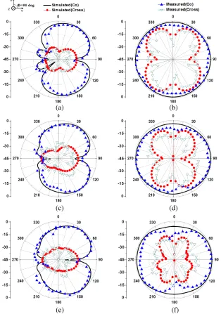
existence of taper-shaped ground, the patterns ofE-plane (XOY) are slightly tilted forward compared with conventional monopole antenna with flat ground, andH-plane (Y OZ) are compressed at Θ = 0 deg. Fig. 6 and Fig. 7 give the normalized radiation patterns of state S2 and stateS3.
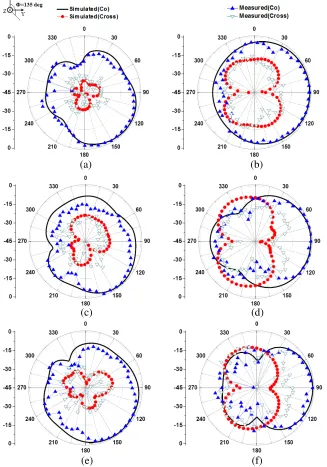
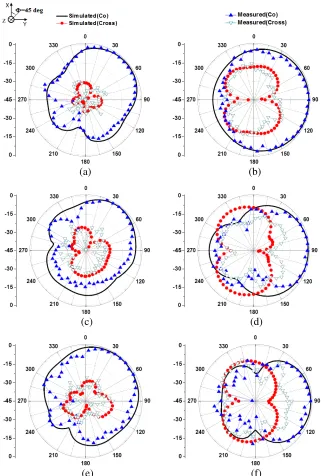
As shown in Figures 6 and 7, for states S2 and S3, antenna radiated at about Φ = 45 deg and Φ = 135 deg, respectively. It can be explained by that two ground arms of the antenna are formed by rotating common limb around Z axis for ±90 degrees and then tailored. So the inner edges of two tapered slots are symmetrical with Φ = 45 deg axis and Φ = 135 deg axis in XOY plane, respectively. Consequently, the main beam of end-fire modes is skewed by around ±45 degrees from Y axis in a wideband.
(a) (b)
(c) (d)
(e) (f)
(a) (b)
(c) (d)
(e) (f)
Figure 7. Normalized radiation patterns of stateS2 (End-fire mode). (a)E-plane (XOY) at 3.5 GHz, (b) H-plane (Φ = 45 deg) at 3.5 GHz, (c) E-plane at 4.5 GHz, (d) H-plane at 4.5 GHz, (e) E-plane at 5.5 GHz, (f) H-plane at 5.5 GHz.
Table 2. Measured and simulated impedance bandwidths of the proposed antenna.
S1 S2 S2
BW (GHz) BW (GHz) BW (GHz)
Measured 3.90–5.48 3.26–6.03 3.25–6.01
4. CONCLUSION
A wideband clubs-shaped antenna with reconfigurable radiation pattern is presented. By changing the off-on states of two PIN diodes, the proposed antenna radiates at three pattern modes: one monopole mode with a bandwidth of 1.58 GHz (3.90–5.48 GHz) and two end-fire modes, with the bandwidths are respectively 2.84 GHz (3.26–6.03 GHz) radiated at Φ = 135 deg, and 2.77 GHz (3.25–6.01 GHz) radiated at Φ = 45 deg approximately. Measured results match well with the simulation and show steady radiation across working band. Therefore, this antenna is suitable for wideband wireless communication applications.
REFERENCES
1. Ye, M. and P. Gao, “Back-to-back F semicircular antenna with frequency and pattern reconfigurability,”Electronics Letters, Vol. 51, No. 25, 2073–2074, 2015.
2. Yang, X. X., B. C. Shao, F. Yang, et al., “A polarization reconfigurable patch antenna with loop slots on the ground plane,”IEEE Antennas&Wireless Propagation Letters, Vol. 11, No. 1, 69–72, 2012.
3. Lim, I., T. Yun, and S. Lim, “Low-profile pattern-reconfigurable antenna with vertical and horizontal shorting lines in grounded CPW technology,” IEEE Antennas & Wireless Propagation Letters, Vol. 13, No. 4, 1589–1592, 2014.
4. Pendharker, S., R. K. Shevgaonkar, and A. N. Chandorkar, “Optically controlled frequency-reconfigurable microstrip antenna with low photoconductivity,” IEEE Antennas & Wireless Propagation Letters, Vol. 13, No. 13, 99–102, 2014.
5. Li, L., Z. Wu, K. Li, et al., “Frequency-reconfigurable quasi-Sierpinski antenna integrating with dual-band high-impedance surface,”IEEE Transactions on Antennas&Propagation, Vol. 62, No. 9, 4459–4467, 2014.
6. Kou, N. and L. Li, “Frequency and pattern reconfigurable annular slot antenna with two feeding ports,”IEEE International Wireless Symposium, 1–4, 2014.
7. Ren, J., X. Yang, J. Yin, et al., “A Novel antenna with reconfigurable patterns using H-shaped structures,”IEEE Antennas & Wireless Propagation Letters, Vol. 14, 915–918, 2015.
8. Jusoh, M., T. Aboufoul, T. Sabapathy, et al., “Pattern-reconfigurable microstrip patch antenna with multidirectional beam for WiMAX applicatio,” IEEE Antennas & Wireless Propagation Letters, Vol. 13, No. 1933, 860–863, 2014.
9. Jeong, J. G., J. Ahn, Y. J. Yoon, “Ultra-wideband reconfigurable radiation pattern antenna for diversity applications,” Electronics Letters, Vol. 51, No. 25, 2086–2087, 2015.