Scholarship@Western
Scholarship@Western
Electronic Thesis and Dissertation Repository
9-18-2017 12:15 PM
Numerical Simulations of Two-Phase Flows in the Liquid Solid
Numerical Simulations of Two-Phase Flows in the Liquid Solid
Circulating Fluidized Bed
Circulating Fluidized Bed
Hao Luo
The University of Western Ontario
Supervisor Chao Zhang
The University of Western Ontario Co-Supervisor Jesse Zhu
The University of Western Ontario
Graduate Program in Mechanical and Materials Engineering
A thesis submitted in partial fulfillment of the requirements for the degree in Master of Engineering Science
© Hao Luo 2017
Follow this and additional works at: https://ir.lib.uwo.ca/etd Part of the Other Mechanical Engineering Commons
Recommended Citation Recommended Citation
Luo, Hao, "Numerical Simulations of Two-Phase Flows in the Liquid Solid Circulating Fluidized Bed" (2017). Electronic Thesis and Dissertation Repository. 4918.
https://ir.lib.uwo.ca/etd/4918
This Dissertation/Thesis is brought to you for free and open access by Scholarship@Western. It has been accepted for inclusion in Electronic Thesis and Dissertation Repository by an authorized administrator of
i
The liquid-solid circulating fluidized bed (LSCFB) has many potential applications in
biochemical and petroleum industries, as well as in wastewater treatments, given its higher
contact efficiency and being able to accommodate two reactions under one system. With
extensive experimental results becoming available, there is clearly a need for computational
fluid dynamics (CFD) modeling to expand our understandings of LSCFBs and to predict the
hydrodynamic behaviors of the two-phase flows within LSCFB.
In this research, the Eulerian-Eulerian two-phase model combined with the kinetic theory for
the granular phase is applied to simulate the two-phase flows in LSCFBs. The key factors
affecting the simulation results including the drag model, near wall treatment and boundary
condition are investigated and the CFD model is validated by comparing the numerical results
with the experimental data. Then, the hydrodynamics of LSCFBs under different operating
conditions are investigated numerically.
Among the seven different drag models examined in this study, the adjusted Syamlal O’Brien
drag model and the irregular particle drag model were found to provide the best numerical
solutions for spherical and irregular particles, respectively. For the three different near wall
treatments tested, the Menter-Lechner near wall treatment was found to provide the best
predictions for the near wall region. It is also found that the numerical results are insensitive
to the restitution and specularity coefficients, which are used in the boundary conditions for
the solid phase. In addition, the proposed CFD model with the best drag model and near wall
treatment is applied to simulate the two-phase flows in LSCFBs under different operating
conditions, including different superficial liquid velocities, superficial solid velocities and
particle densities. The numerical predictions show correct trends and good agreements with
the experimental data.
Keywords
Numerical Simulation, Computational Fluid Dynamics (CFD), Liquid-Solid Circulating
ii
Acknowledgments
I will like to take this opportunity to express the gratitude and appreciation to those who have
always been helping and supporting me in the whole period of master’s study.
Firstly, my sincerest gratitude is to my supervisors Profs. Zhang and Zhu, who believed my
potential and provided generous advice, encouragement and support throughout my research.
I attribute the thesis to their guidance which ensured the successful fulfilment of this study.
Then, my gratefulness is from all the members from research groups of Profs. Zhang and Zhu,
especially Zeneng Sun, Huirui Han, Yunfeng Liu and Tian Nan for their help and friendship
in both academic and daily life.
Finally, great gratitude is to my parents for their consistent and unreserved support throughout
iii
Table of Contents
Abstract ... i
Acknowledgments... ii
Table of Contents ... iii
List of Tables ... vi
List of Figures ... vii
List of Appendices ... xi
Nomenclature ... xii
Chapter 1 ... 1
1 General Introduction ... 1
1.1 Background ... 1
1.2 Literature review ... 4
1.2.1 Hydrodynamic characteristics of LSCFBs... 4
1.2.2 Theory of the modeling of multi-phase flows in fluidized beds ... 9
1.3 Objectives and thesis structure... 16
1.3.1 Objectives and new contributions ... 16
1.3.2 Thesis structure ... 17
References ... 18
Chapter 2 ... 23
2 Evaluations of CFD Models for the Liquid-Solid Circulating Fluidized Beds (LSCFBs) ... 23
2.1 Introduction ... 23
2.2 Experimental setup of the LSCFB system ... 26
2.3 Numerical models ... 29
2.3.1 Governing equations ... 29
iv
2.3.3 Adjustment of the drag model... 36
2.3.4 Near wall treatment ... 39
2.4 Numerical methodology... 40
2.5 Results and discussion ... 43
2.5.1 Studies of the drag models for spherical particles ... 43
2.5.2 Studies of the near wall treatments ... 49
2.5.3 Studies of the specularity and restitution coefficients ... 53
2.5.4 Studies of the drag model for irregular particles ... 57
2.6 Conclusions ... 60
References ... 62
Chapter 3 ... 65
3 Numerical Investigations of Hydrodynamics in Liquid-Solid Circulating Fluidized Beds under Different Operating Conditions ... 65
3.1 Introduction ... 65
3.2 Experimental setup of the LSCFB system ... 68
3.3 Numerical models ... 71
3.3.1 Governing equations ... 71
3.3.2 Drag models ... 74
3.3.3 Near wall treatments ... 78
3.4 Numerical methodology... 78
3.5 Results and discussion ... 82
3.5.1 General hydrodynamics of LSCFB ... 82
3.5.2 Effects of Us under the same Ul ... 86
3.5.3 Effects of Ul under the same Us ... 92
3.5.4 Effects of particle density for irregular particles ... 96
v
Chapter 4 ... 101
4 Conclusions and Recommendations ... 101
4.1 Conclusions ... 101
4.2 Recommendations ... 102
Appendices ... 104
vi
List of Tables
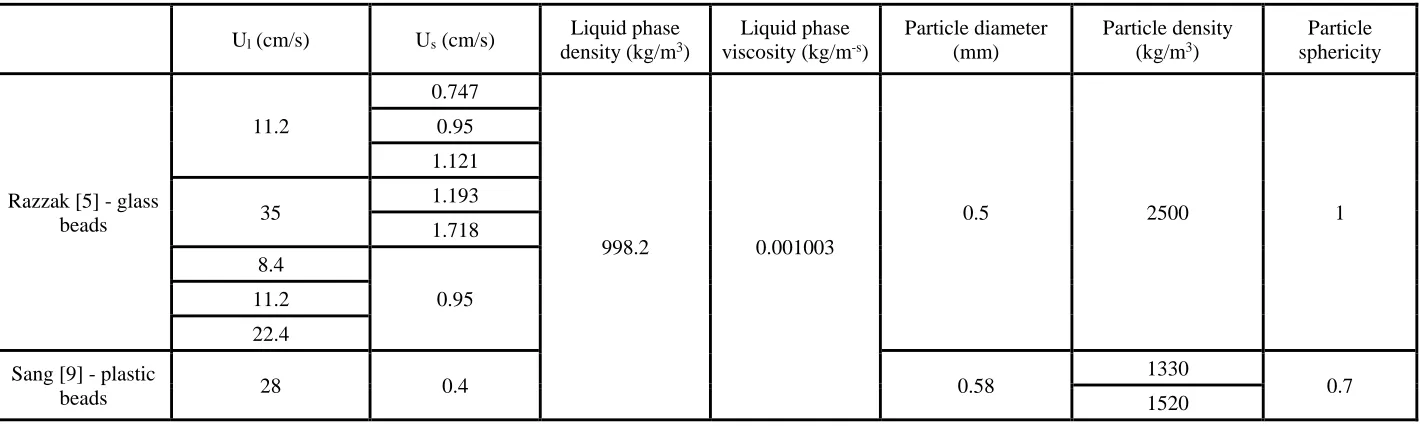
Table 2.1: Operation conditions and physical properties of the particles and liquid ... 29
Table 2.2: Constitutive equations for the solid phase ... 30
Table 2.3: Mesh information for different operating conditions ... 42
Table 2.4: Difference between the numerical results and experimental data using different drag models H=3.82m under Ul= 11.2 cm/s and Us= 0.747 cm/s ... 46
Table 2.5: Difference between the numerical results and experimental data using different drag models at H=1.01m under Ul= 35 cm/s and Us= 1.193 cm/s ... 46
Table 2.6: Difference between the numerical results and experimental data using different near wall treatments at H=1.01m under Ul= 35 cm/s and Us= 1.193 cm/s ... 50
Table 2.7: Difference between the numerical results and experimental data using different drag models at H=1.01m under Ul= 35 cm/s and Us= 1.193 cm/s ... 52
Table 3.1 Operation conditions and physical properties of the particles and liquid ... 70
Table 3.2 The constitutive correlations for the transport equations ... 73
vii
List of Figures
Figure 1.1: Schematic diagram of a liquid-solid circulating fluidized bed ... 3
Figure 1.2: Axial distributions of the solids holdup in the LSCFB for steel shots under different superficial liquid velocities (Zheng et al., 1999) ... 6
Figure 1.3: Axial profiles of the average cross-sectional solids and liquid holdup at Ul=22.4 cm/s (Razzak, 2009) ... 6
Figure 1.4: Radial profiles of the solids concentration at H=0.8m (Zheng et al., 2001) ... 8
Figure 1.5: Comparison of the radial distributions of the solids holdup between glass beads and lava rock particles at H=2.02 m and Up=22.4 cm/s (Razzak, 2009) ... 9
Figure 2.1: Experimental setup of the LSCFB riser ... 28
Figure 2.2: Schematics of the LSCFB riser ... 42
Figure 2.3: Diagram of the mesh created for simulations ... 42
Figure 2.4: Comparisons of the radial distributions of the solids holdup using different drag models under Ul= 11.2 cm/s and Us= 0.747 cm/s ... 44
Figure 2.5: Comparisons of the radial distributions of the solids holdup using different drag models under Ul= 35 cm/s and Us= 1.193 cm/s ... 45
Figure 2.6: Comparison of the radial distributions of the granular temperature using different drag models at H= 3.82m under Ul= 11.2 cm/s and Us= 0.747 cm/s ... 48
Figure 2.7: Comparison of the radial distributions of the granular temperature using different drag models at H= 1.01m under Ul= 35 cm/s and Us= 1.193 cm/s ... 48
Figure 2.8: Comparison of the radial distributions of the solids holdup using different near wall treatments at H= 1.01m under Ul= 35 cm/s and Us= 1.193 cm/s ... 50
viii
Figure 2.10: Comparison of the radial distributions of the solids holdup using different drag
models at H=1.01m under Ul= 35 cm/s and Us= 1.193 cm/s ... 52
Figure 2.11: Comparisons of the radial distributions of the solids holdup using different restitution coefficients for the specularity coefficient of 0.0005 under Ul= 35 cm/s and Us= 1.193 cm/s ... 54
Figure 2.12: Comparisons of the radial distributions of the solids holdup using different specularity coefficient for the restitution coefficient of 0.95 under Ul= 35 cm/s and Us=1.193 cm/s ... 55
Figure 2.13: Comparisons of the radial distributions of the solids holdup under Ul = 11.2cm/s and Us= 0.747cm/s at different axial locations ... 56
Figure 2.14: Comparisons of the radial distributions of the solids holdup under Ul = 35cm/s and Us =1.193cm/s at different axial locations ... 57
Figure 2.15: Comparison of the radial distributions of the solids holdup for different drag models at H=3.98m under Ul=28 cm/s and Us=0.4 cm/s with irregular particles ... 58
Figure 2.16: Comparison of the radial distributions of the granular temperature using different drag models at H=3.98m under Ul=28 cm/s and Us=0.4 cm/s with irregular particles ... 59
Figure 3.1: Experimental setup for the LSCFB riser ... 69
Figure 3.2: Schematics of the LSCFB riser ... 80
Figure 3.3: Diagram of the mesh created for simulations ... 80
Figure 3.4: Axial distribution of the cross-sectional averaged solids velocity ... 83
Figure 3.5: Axial distribution of the cross-sectional averaged solids holdup ... 83
ix
experimental and numerical results at different axial locations under Ul= 22.4cm/s and
Us= 0.95cm/s ... 85
Figure 3.8: Radial distributions of the solids velocity at different axial locations under
Ul= 22.4cm/s and Us= 0.95cm/s ... 86
Figure 3.9: Comparison of the axial distributions of the cross-sectional averaged solids holdup
under different operating conditions ... 87
Figure 3.10: Comparisons of the radial distributions of the solids holdup between the
experimental and numerical results at different axial locations under Ul=11.2cm/s and
Us=0.747,0.951 and 1.121cm/s ... 88
Figure 3.11: Comparison of the radial distributions of the solids velocity at different axial
locations under Ul=11.2cm/s and Us=0.747,0.951,1.121cm/s ... 90
Figure 3.12: Comparison of the radial distributions of the solids velocity at different axial
locations under Ul=35cm/s and Us=1.193, 1.718 cm/s ... 91
Figure 3.13: Axial distributions of the cross-sectional averaged solids holdup under
Us=0.95 cm/s while Ul=8.4, 11.2, 22.4 cm/s ... 92
Figure 3.14: Comparisons of the radial distributions of the solids holdup between experimental
and numerical results at different axial locations under Us=0.95 cm/s, and Ul= 8.4, 11.2 and
22.4 cm/s ... 93
Figure 3.15: Radial distributions of the solids velocity at different axial locations under
Us=0.95 cm/s, and Ul= 8.4, 11.2 and 22.4 cm/s ... 95
Figure 3.16: Axial distributions of the cross-sectional averaged solids holdup for
p
x
Figure 3.17: Comparisons of the radial distributions of the solids holdup between experimental
xi
List of Appendices
Appendix A ... 104
xii
Nomenclature
Notation
Ap Cross-sectional area of a particle (m2)
Ar Archimedes number
1
C Constants
2
C Constants
D
C Drag coefficient, dimensionless
p
d Mean particle diameter, m
D Riser diameter, m
H Riser height, m
e Specularity coefficient, dimensionless
sw
e Restitution coefficient for particle-wall collisions’, dimensionless
g Acceleration due to gravity, m/s2
O
g Radial distribution function, dimensionless
k Turbulent kinetic energy, m2/s2
sl
K Interphase momentum exchange coefficient, kg/m3s
s
P Solids pressure, Pa
P Fluid pressure, Pa
e
R Reynolds number, dimensionless
t Time, s
t
U Particle terminal velocity, m/s
l
U Superficial liquid velocity, m/s
s
U Superficial solid velocity, m/s
v Velocity, m/s
Greek letters
s
local solids volume fraction, dimensionless
Turbulent energy dissipation rate, m2/s3
s
k Granular conductivity, kg/m3s
ls
Interphase energy exchange, kg/ms3
Collisional energy dissipation rate, kg/ms3
Solids bulk viscosity, kg m/s
Viscosity, kg/m-s
Kinematic viscosity, m2/s
Granular temperature, m2/s2
xiii
, k
Constants
Shear stress, kg/s2
Subscripts
l Liquid phase
s Solid phase
f Fluid
a Auxiliary
mf Minimum fluidization
Chapter 1
1
General Introduction
1.1
Background
Fluidization is characterized as a process in which solid particles are suspended in a moving
fluid and converted from the solid-like state to the fluid-like state. With the characterization of
higher fluid-solid contact efficiency, better fluid-solid and solid-solid mixing, the fluidization
has been widely applied in various industries, including the wastewater treatment, biochemical
technology, petrochemical and metallurgical industries.
Based on the characterization of the fluid media, fluidization can be cataloged as gas-solid
fluidization, liquid-solid fluidization and gas-liquid-solid fluidization. Liquid-solid
fluidization can be divided into four regimes, the fixed bed regime, the conventional
fluidization regime, the circulating fluidization regime and the dilute transport regime. When
a liquid stream is introduced from the bottom of a bed with solid particles, it will pass through
the bed via the spaces between static particles. If the liquid velocity is low which cannot
balance the weight of particles, particles tend to stay static at the bottom of the bed, which is
called the fixed bed regime. With the increase of the liquid velocity, the drag force acting on
particles increases correspondingly and gradually counteracts the effect of gravity. When the
fluid velocity reaches the minimum fluidization velocity, Umf , where the drag force, gravity
and buoyancy force reach balance, particles start suspending in the fluid and transforming to
fluid-like state. Indicating the start of the conventional fluidization regime where the particles
are not entrained out of the bed. With further increase in the fluid velocity, so as the drag force,
the fluidization becomes more intense and particles are moving upward along with the bed
expansion. Finally, it reaches the circulating fluidization regime where most particles can be
entrained out of the bed and need to be recirculated back to the bottom of the bed. Further
increasing the liquid velocity, the bed goes into the dilute liquid transport regime.
The conventional fluidization regime has been studied extensively by lots of researchers. In
terms of the flow structures, a clear boundary between the dense region with a higher solid
concentration at the top of the bed can be widely observed in experiments, and with the increase
in the liquid flow rate, the boundary raises with the expansion of the bed. In 1985, Couderc [1]
found the conventional fluidization can be considered as a dispersed homogenous fluidization
where particles are uniformly distributed in both the axial and radial directions in the dense
region. As for the mathematical models describing the flow characteristics, Richardson and
Zaki [2] proposed an important relationship between the operating liquid velocity and the bed
voidage, which has been widely adopted and modified for the drag correlation between the
liquid and particles.
Due to the restricted operating range and back-mixing problems of the conventional
fluidization, the circulating fluidized bed (CFB) was proposed in late 1960s. The gas-solid
circulating fluidized bed (GSCFB) has been extensively studied, it was found the back-mixing
phenomenon in GSCFBs can be significantly reduced [3] and the contact efficiency is also
increased due to the increased slip velocity between the two phases [4]. However, compared
to GSCFBs, only in recent years, the liquid-solid circulating fluidized bed (LSCFB) has gained
more attention. The studies of hydrodynamics in LSCFBs have been mostly carried out at
Tsinghua University [5-9] and University of Western Ontario [10-13].
In LSCFBs, all particles can be entrained out of the bed with the high liquid velocity, which is
usually higher than the particle terminal velocity. Hence, it is essential to feed particles at the
bottom of the fluidized bed continuously, which is normally done by feeding new particles or
recirculating the entrained particles back to the bottom of the bed. The schematic of a typical
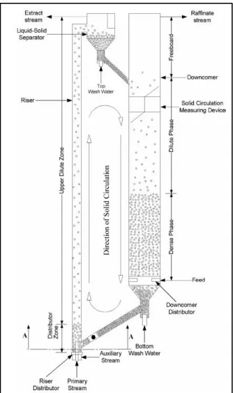
LSCFB is shown in Fig 1.1, which comprises of a riser, a downer, a liquid-solid separator, a
top solid-return pipe and a bottom solid-feed pipe [14]. The particles are injected from the
solids feed pipe, due to the auxiliary liquid and primary liquid, the particles are moving upward
and entrained out of the riser, then separated from liquid in the liquid-solid separator and
To properly design a LSCFB system for industrial applications, it is necessary to understand
the hydrodynamics of the LSCFB system. Liang and Zhu [9], Kuramoto [15], Zheng [10] and
Razzak [16] have reported that the flow structure is almost uniform in the axial direction of
LSCFBs for all types of particles, which is different from the conventional liquid-solid
fluidized beds where exits a boundary between the bottom dense region and the top freeboard
region. In addition, Liang et al. [8], Zheng [12], Razzak [16] and Sang [13] observed the
non-uniformity of the flow structure in the radial direction of LSCFBs for different particles and
operating conditions, which is different from the uniform distribution in conventional
liquid-solid fluidized beds.
Modeling on the fluidized beds has become a new tool to investigate and scale up the complex
flow structures. Starting from the 1950s, a series of mathematical models have been proposed,
such as the two-phase model for the conventional fluidized beds and the core-annulus model
for the circulating fluidized beds. However, those models cannot correctly and
comprehensively solve the flow field of a complex system in fluidized beds. Hence, with fast
development of computational techniques, computational fluid dynamics (CFD) has become a
more reliable and effective way to simulate a complex flow system.
The literature review of recent research on the hydrodynamics of LSCFBs and CFD techniques
are presented in next section, along with the gaps and some discrepancies, which leads to the
objectives and thesis structure of this research work.
1.2
Literature review
The literature review section is conducted in two areas, (1) past experimental studies on the
hydrodynamics of the LSCFB system and (2) the relevant CFD models for the multi-phase
flow simulations.
1.2.1
Hydrodynamic characteristics of LSCFBs
Plenty of experimental studies have been conducted on the conventional liquid-solid fluidized
bed since 1950s. As mentioned before, it is generally accepted that the liquid-solid fluidization
is a uniformly dispersed homogeneous fluidization along both axial and radial directions under
and axial directions. This homogeneous fluidization phenomenon was first brought by
Richardson and Zaki [2] along with the important correlation between the operating liquid
velocity and the bed voidage, which is used as the basis of the liquid-solid fluidization theory.
Later, many researchers have confirmed the homogeneous fluidization under all liquid-solid
fluidized systems where the liquid velocity is lower than the particle terminal velocity [17-19].
Few works have been concentrated on the liquid-solid fluidization system under high liquid
velocity. Zheng [10] reported there are two distinct regimes for circulating fluidization under
a settled auxiliary liquid flow rate: (1) the initial zone where solids circulation rate increases
significantly with the increase in the liquid flowrate and (2) the fully developed zone in which
the solids circulation rate increases insignificantly with the increase in the liquid flowrate.
Liang and Zhu [9] reported that the axial solids volume fraction distributions in LSCFBs are
uniform under different superficial liquid velocities and particle circulation rates for two
low-density particles. Later, Zheng [10] extended the experimental studies to heavy particles and it
was found that the axial solids volume fraction distribution is non-uniform for heavy particles
as shown in Figure 1.2, but the overall flow structures in LSCFBs are still more uniform than
GSCFBs. In addition, it was also found that a higher liquid velocity and longer transition
regime are required for heavy particles when transiting from the conventional fluidization
regime to the circulating fluidization regime. Razzak [16] investigated the influence of the
particle diameter and shape on the behaviors of LSCFBs, it is shown in Figure 1.3 that the axial
solids holdup distribution is almost uniform expect at the region near the distributor, while the
overall cross-sectional average solid holdup increases with the increase in the particle diameter
Figure 1.2: Axial distributions of the solids holdup in the LSCFB for steel shots under different superficial liquid velocities (Zheng et al., 1999)
For the radial directions, Liang et al. [8] and Roy et al. [20] showed the non-uniform radial
distribution of the solid holdup in the LSCFBs, i.e., it is lower at the central region while higher
near the wall. Later, Zheng [12] conducted the experimental studies under different operating
conditions and particle properties, it can be seen from Fig 1.4 that the radial nonuniformity
decreases with the increase of the superficial liquid velocity and increases with the increase of
the superficial solid velocity. Furthermore, more uniform distribution along the radius is
observed for systems where lighter particles are used under the same cross-sectional average
solids concentration. Later, the above phenomena were examined by Razzak [16] and the
investigations were extended to different particle diameters and shapes. In terms of the particle
size, it was reported the radial nonuniformity and local solid concentration are higher for
smaller particles under the same operating conditions. In addition, by increasing the superficial
solid velocity, the radial nonuniformity increases and the rate of the increase in the radial
nonuniformity is higher for smaller particles. In terms of the particle shape, Razzak [16]
observed the solids holdup of spherical glass beads is higher than irregular lava rocks, which
is due to the reduction in the drag coefficient caused by the irregular shape of the particles.
Sang [13] later investigated the effects of the particle density, size and sphericity on the
hydrodynamic behaviors in LSCFBs and introduced a new criterion, the excess superficial
liquid velocity (UlUt), which can give a better indication for the influence of the particle properties on the performance of the LSCFBs. Then, a mathematical expression was proposed
(a)
(b)
Figure 1.5: Comparison of the radial distributions of the solids holdup between glass beads and lava rock particles at H=2.02 m and Up=22.4 cm/s (Razzak, 2009) Although there are some radial or axial nonuniformities exist in LSCFBs under some operating
conditions, the flow structures in liquid-solid circulating fluidized beds are more homogeneous
than the distributions in gas-solid circulating fluidized beds.
1.2.2
Theory of the modeling of multi-phase flows in fluidized beds
In recent years, the computational fluid dynamics (CFD) modeling has become an effective
tool to investigate the hydrodynamics in a CFB riser due to the fast development of computer
technology and multiphase flow models [21-24]. Generally, there are two major theories of
describing gas-solid and liquid-solid two-phase flows: (1) the Eulerian-Lagrangian (E-L)
particle-particle interactions are neglected and (2) the Eulerian-Eulerian (E-E) approach where
two-fluid model is used for both phases. In this work, the Eulerian-Eulerian approach is employed
since the solid volume fraction in LSCFBs is high and the interactions between particles need
to be considered.
The Eulerian two-phase flow theory was developed by Ishii [25], Delhaye and Achard [26],
Boure and Delhaye [27], Soo [28], Dre and Lahey [29] and He and Simonin [30]. The general
idea of Eulerian-Eulerian approach is to consider the fluid and solid phases as the
interpenetrating continuum, and solve the mass and momentum governing equations which are
closed by the constitutive equations within a fixed control volume containing both phases [31].
Furthermore, the liquid phase is closed by a turbulence model and the solid pressure, viscosity
and solid phase stress tensor are described by the kinetic theory of granular phase (KTGP). By
applying the E-E approach, a series of investigations and evaluations for multi-phase flows
have been conducted in recent years.
Several turbulence models that are used to close the Reynolds-averaged Navier-Stokes
equations for the fluid phase have been developed to represent the Reynolds stresses and can
be cataloged into four groups.
(1) The zero-equation turbulence model. This model is developed from a simple algebraic
equation proposed by Van Driest [32] to close the governing equations instead of using PDE
to describe the turbulent stresses and fluxes. Then, Cebeci and Simth [33], and Baldwin and
Lomax [34] refined and improved the model from Van Driest [32].
(2) The one-equation turbulence model. Based on the Boussinesq hypothesis [35] which relates
the Reynolds stresses with the mean velocity gradients, the Spalart-Allmaras model [36] was
developed to solve the turbulence kinetic energy k.
(3) The two-equation turbulence model. On the base of the one-equation turbulence model, the
two-equation models, such as the k-ε and k–ω models, were proposed where two additional
equations are solved for the turbulence kinetic energy k, and the turbulence dissipation rate ε
(4) The Reynolds stress model (RSM). This turbulence model abandons the isotropic
eddy-viscosity hypothesis and closes the Reynolds-averaged Navier-Stokes equations by solving
transport equations for the six Reynolds stresses, together with an equation for the dissipation
rate [37].
After decades of developments, the k-ε and k–ω turbulence models have become the most
popular ones. With the characteristics of robustness, economy and reasonable accuracy for
various turbulent flows, the k-ε turbulence model is widely used in industrial applications.
Since the standard k-ε turbulence model is for high Reynolds number flows, it is necessary to
modify it for flows in low Reynolds number regions or use wall functions near the wall.
Correspondingly, the k–ω turbulence model, which accounts for the effects of low Reynolds
number flows, compressibility and shear flow spreading, performs better for swirling flows
and flows in the near wall region, but with the disadvantages of less range of applications and
over predicting separations as well. As for the RSM model, it is much more computational
expensive and mostly used to solve the flow with anisotropic turbulence such as highly
swirling flows and stress-driven secondary flows [37].
For the kinetic theory of granular phase, to model the kinetic and collisional transport of
particles while representing granular phase as interpenetrating continuum with fluid, the KTGP
was developed in 1980s. It started from the collisional particle interactions of dense fluid flow
which was presented by Chapman and Cowling [38] and has been widely applied in multiphase
flow simulations, such as the works by Lun et al. [39], Ding and Gidaspow [24]. By analogizing
the thermodynamic temperature of fluid, the granular temperature for solid particles was
introduced, which is associated with the fluctuating velocity of solid particles. Thus, the solids
viscosity and pressure can be determined by the granular temperature and the constitutive
equation of the solid momentum equation can be closed by solids stress tensor. Furthermore,
when dense gas molecules interact, the collisions are nearly elastic. However, for the particles
which are a few orders larger than molecules, they will suffer a loss of momentum during
collisions. Therefore, the restitution coefficient is introduced to describe the inelasticity of the
Within the Eulerian-Eulerian multiphase model, the interactions between particles and fluid is
a dominate factor that should be considered. The dynamic balance of particles within a fluid
depends on the drag, gravity and buoyancy forces. Hence, it is essential to have a drag model
that is suitable for particle fluidization processes under different conditions, including different
properties of solids and fluid, Reynolds number, volume fraction, etc., which has become the
key challenge in multiphase flow simulations [40]. During the past decades, starting from the
easiest single particle drag correlations [41] to the complex semi-empirical multi-particle drag
models, researchers have proposed three approaches. The first approach is by correlating the
pressure loss (drag force on a particle) with the voidage of the packed bed fluidization regime,
such as the Ergun equation [42]. Then Gibilaro [43] extended its applicability to the dilute
particle systems by relating the energy dissipation in the bed with the unrecoverable pressure
loss, and hence obtained an expression of particle drag force under the fully expanded limit
condition. The second approach is by correlating the slip velocity between the particle and
liquid, with the bed voidage for different fluidized bed regimes, such as Richardson-Zaki [2],
Garside and Al-Dibouni [44] and Wen-Yu [45]. Then Syamlal-O’Brien [46] obtained the drag
model for the multi-particle system from a single particle drag correlation by non-dimensional
analysis. The third approach is EMMS, which is based on the energy minimization multi-scale
method. Beside the above three methods, Gidaspow [47] combined the first method (Ergun
equation) and the second method (Wen-Yu) to obtain the drag coefficients on the dense
fluidization regime (ε<0.8) and dilute fluidization regime (ε>0.8) respectively. Then,
Huilin-Gidaspow [48] improved the discontinuity of the Huilin-Gidaspow drag model [47] by introducing a
blending function. Furthermore, since some operating conditions are significantly different
from the original experimental conditions that Syamlal and O’Brien considered when deriving
their drag model [46], the Syamal-O’Brien model can be adjusted by matching the predicted
minimum fluidization velocity with the experimental data. It is called the adjusted
Syamlal-O’Brien drag model [49].
Beside the drag model, in the near wall region of CFBs, due to the considerable influence of
walls on turbulent flows, an accurate representation of the flow in the near wall region should
be adopted to ensure the numerical solutions of the wall-bounded flow are accurate. Generally,
there are two approaches to model the flow in the near-wall region [37]. The first one is by
turbulence equations, such as the standard wall functions and the scalable wall functions. The
second one is by modifying the turbulence model to resolve the near wall region flows, such
as the enhanced wall treatment and the Menter-Lechner near wall treatment [37]. The standard
wall functions are based on the work of Launder and Spalding [50] and the scalable wall
functions is based on the standard wall functions by adding a selector for Y*. As for the second
approach, the enhanced wall treatment is based on the two-layer model with a blend function
while the Menter-Lechner near wall treatment adds a source term in the transport equation of
the turbulence kinetic energy and introduces new momentum equations [48].
For the particle-particle collisions, Gidaspow and Huilin [51] introduced the “effective
restitution coefficient” which is near 1 to represent the near elastic collision brought by the
liquid film between particles which attenuates the energy loss within particle collisions. Cheng
[52] also claimed the “elastic collisions” phenomenon exists in LSCFBs and found there is
only minor difference in radial distribution of liquid velocity and solids holdup while particle
restitution coefficient varies from 0.96 to 0.99. On the one hand, the collision is related to the
materials of particles, the glass beads which were used in the works by Gidaspow and Huilin
[51] and Cheng [52] shows the particle restitution coefficient equals to 1.0, while Ehsani [53]
indicated particle restitution coefficient=0.9 is more suitable for the rougher stainless steel
spherical particles. On the other hand, the fluid materials have considerable influence on the
particle-particle collisions within the fluid-solid suspension as well. For example, gas can
hardly form a lubricant film between particles which eases the particle collisions and the
existence of clusters can also significantly influence the particle collisions in gas-solid systems.
For the boundary conditions, interactions between fluid and wall for the wall bounded flow
need to be considered as well. In most of fluid flows, no-slip condition is applied on the wall.
However, for the particles flow in a fluidized bed, the no-slip condition at the wall is not
applicable. Hence, the specified shear is required to set at the wall if the shear stress is known.
Otherwise, the conception of specularity coefficient introduced by Johnson and Jackson [54]
can be used, which represents the fraction of collisions that transfer momentum from the
granular flows to the wall. When it approaches zero, it stands for the complete elastic collision
and the condition is equivalent to zero shear at the wall, while it closes to unity indicates there
In the industrial applications of fluidized beds, irregular particles are used sometimes which
can significantly affect the hydrodynamics of the fluidized bed. Generally speaking, the more
irregular particle shape is, the greater the drag will be. Therefore, it is important to investigate
the influence of particle shape on the modeling. The irregular particles can be various kinds of
shapes. Hence, it is essential to introduce shape factors to characterize irregular particles.
Wadell [55] introduced the sphericity, which is the ratio of the surface area of a sphere of the
same volume and the surface area of the particle, and the circularity, which stands for how
close the projected area of the particle is a circle. Analogously, Heywood [56] suggested a
volumetric shape factor, which is related to the diameter of a sphere with the same volume and
the diameter of a circle of the same area as the projected area of the particle. Later, people
proposed other indirect methods to describe the sphericity. Austin [57] determined the shape
factor by the specific surface and the arithmetic average of passing and retaining sieve,
McCulloch and Moser [58] defined the “dynamic shape factor”, which is based on hydraulic
properties of the irregular particle.
On the base of the conception of the shape factor, efforts are made to develop the drag models
for irregular particles. Starting from the 1970s, simple drag correlations for particles with fixed
shapes and flow directions have been derived. For example, Huner and Hussey [59] and Ui et
al. [60] studied cylinders moving in the axial direction, and Shail and Norton [61] studied discs.
Undoubtedly, some drag models are accurate for particles with certain shapes under certain
flow conditions, but they are not accurate for other circumstances. Therefore, a universal drag
correlation using shape factors for irregular particles will be essential and changeling. The
attempts to develop the drag model for single non-spherical particles were made by Haider and
Levenspiel [62], Ganser [63], Swamee and Ojha [64], Chien [65], Tran-Cong et al. [66]. Those
empirical correlations are mainly based on experimental data. However, all those models were
obtained based on single particle drag correlation, and they still need to be improved and
modified for the multi-particle systems in fluidized beds. Therefore, Richardson and Zaki [2]
included the volumetric shape factor in their velocity-voidage function under the limited
condition of Re500 for relatively large particles (d 100m ) with irregular shapes.
Cleasby and Fan [67] incorporated the “n” value from the RZ equation [2] with a function of
flints. Then Dharmarajah [68] proposed the relationship between the bed voidage, sphericity,
and superficial liquid velocity by introducing complicated terms of modified Reynolds number
and coefficient A1. However, this relationship is not suitable for bed voidage higher than 0.9.
Comparing to GSCFBs, less CFD studies have been carried out on LSCFBs. Since both
GSCFB and LSCFB are two phase flows, the difference is the carrying fluid property. So, the
models for those two types of fluidized beds should be similar in principle. The following part
is the literature reviews for the applications of CFD models on LSCFBs.
Roy et al [69] simulated the flow field in a LSCFB using the Eulerian two-phase model. The
KTGF, Wen-Yu drag model [45], standard k-ε turbulence model, no-slip condition for the
liquid and Johnson and Jackson boundary condition for the particles were chosen. The
numerical results show satisfied agreements with the experimental data on the flow patterns.
It was also found that the simulation result is not sensitive to the restitution coefficient in
LSCFBs.
Abbas [14] employed a CFD model based on Eulerian-Eulerian multi-phase flow with KTGF
to simulate a LSCFB reactor. Three different turbulence models, the mixture, dispersed and
per-phase k-ε models, were investigated. It was reported both the dispersed and per-phase k-ε
turbulence models showed qualitative agreements with the experimental data. However, the
dispersed turbulence model was less computational expensive.
Cornelissen [70] studied the conventional fluidized bed and investigated the influence of the
inlet distributor, restitution coefficients and two different drag models. It was reported that the
uniform discrete orifices gave better hydrodynamic behaviors than the non-uniform distributor,
the Gidaspow drag model [47] predicted a higher voidage than the Wen-Yu drag model [45],
and there was no significant difference by varying restitution coefficient.
Cheng [52] did a parametric study on the particle-particle restitution and particle-wall
restitution coefficient. The results showed that the particle-particle restitution coefficient did
not have influence on the hydrodynamics due to the lubrication effect from the liquid film, and
1.3
Objectives and thesis structure
1.3.1
Objectives and new contributions
In view of the literature reviews presented in the previous section, several CFD models have
been developed to simulate the hydrodynamics of liquid-solid circulating fluidized beds. Some
parameters including drag models, turbulence models, particle-particle restitution coefficient,
and boundary conditions are discussed. However, only a few studies have been carried out to
investigate the applicability of the existing drag models for the LSCFBs and the influence of
the near wall treatment on the turbulence modeling has not been considered. Therefore, the
first objective of the present work is to conduct a comprehensive comparison of various widely
used drag models for LSCFBs. Then, on the basis of the drag model study, the effects of
different near wall treatments are incorporated and investigated. Besides, the Johnson and
Jackson boundary condition [54] is investigated by varying the specularity coefficient and
restitution coefficient. In addition, since irregular particles are often used in industrial
applications, the drag models based on spherical particles might not suitable. Hence, to
improve the accuracy of numerical predictions, the second objective is to develop a drag model
that is suitable for irregular particle systems. Furthermore, due to the lack of the validations of
the numerical results for LSCFBs under different operating conditions, the third objective is to
validate the applicability of the CFD model and investigate the hydrodynamics of LSCFBs
under different operating conditions.
The main contributions of the present work are (1) the systematical studies are carried out for
the performance of the widely used drag models for the LSCFB systems, (2) the solids holdup
distribution and other hydrodynamic behaviors have been successfully improved by
incorporating suitable drag model, near wall treatments and boundary conditions, (3) a new
drag model for irregular particles, which is a modified Syamlal O’Brien drag model, is
proposed and it can improve the agreements between the numerical predictions and
experimental data for the system with irregular particles, (4) the proposed CFD model is
applied for the simulations of LSCFBs under different operating conditions. The predictions
1.3.2
Thesis structure
The thesis is in the “Integrated-Article Format”.
Chapter 1 - A comprehensive review on the hydrodynamics studies on the liquid-solid
circulating fluidized bed system, the theory of CFD model for the multi-phase flows and
some existing studies on CFD models for LSCFB simulations are presented.
Chapter 2 - The applicability of existing drag models for LSCFBs, the performance of the
near wall treatment for the liquid phase due to the inapplicability of turbulence model in
the close-to-wall region, and the Johnson and Jackson boundary condition for the solid
phase are investigated. By analyzing and comparing the numerical and experimental data
under different operating conditions, a comprehensive and improved numerical model for
LSCFBs is proposed. Furthermore, considering that irregular particles are used in
industrial applications, the Syamlal-O’Brien drag model is modified to include the
sphericity effect and the numerical results using the modified drag model are compared
with the experimental data.
Chapter 3 - The applicability of the proposed CFD model is validated. The hydrodynamics
of the LSCFB under different operating conditions are investigated, including the effects
of the superficial liquid velocity, superficial solid velocity and particle density.
References
[1] Couderc J.-P., 1985, Incipient fluidization and particulate systems,' Chapter 1 Fluidization, 2nd edn., eds. J. F. Davidson, R. Clift and D. Harrison, Academic Press, London, pp. 1-46
[2] Richardson JF, Zaki WN. Sedimentation and fluidization: Part I. Process Safety and Environmental Protection: Transactions of the Institution of Chemical Engineers, Part B. 1997;75: S82S100.
[3] Grace, J.R., “High Velocity Fluidized Bed Reactors”, Chem. Eng. Sci. 45, 1953-1966 (1990).
[4] Yang, Y.-L., Y. Jin, Z.-Q. Yu., J.-X. Zhu and H.-T. Bi, “Local Slip Behaviour in the Circulating Fluidized Bed”, AIChE Symp. Ser. 89,81-90 (1993).
[5] Liang, W. g., S. L. Zhang, Z. Q. Yu, Y. Jin and Q. W. Wu, “Liquid-Solids Circulating Fluidized Bed (I). Studies on the Phase Holdups and Solid Circulating Rate”, J. Chem. Ind. & Eng. China (Chinese edition) 44, 666-671 (1993).
[6] Liang, W. G., Q. W. Wu, Z. Q. Yu, y. Jin and Z. W. Wang, “Hydrodynamics of Gas-Liquid-Solid Three-Phase Circulating Fluidized Bed”, in “Fluidization ‘94’”, Science and Technology, Chemical Industry Press, Beijing, China (1994), pp. 329-337.
[7] Liang W.-& Yu Z Q.J, in Y., Wang Z.-W., Wang Y., He M. and Min E., 1995, Synthesis of linear alkylbenzene in a liquid-solids circulating fluidized bed reactor, J. Chem. Technol. Biotechnol., 62,98-102
[8] Liang W.-G., Zhu J.-X., Jin Y., Yu 2.-Q., Wang LW. and Zhou J., 1996, Radial nonuniformity of flow structure in a liquid-solid circulating fluidized bed, Chem. Eng. Sci., 5 1,200 1-20 10.
[9] Liang, W. G., Zhang, S. L., Zhu, J. X., Yu, Z. Q., Jin, Y., & Wang, Z. W. (1997). Flow characteristics of the liquid-solid circulating fluidized bed. Powder Tech., 90, 95–102.
[10] Zheng Y. Flow structure in a liquid-solids circulating fluidized bed [dissertation]. London, Ont: Faculty of Graduate Studies, University of Western Ontario; 1999.
[11] Zheng, Y. and J. X. Zhu, “Microstructural Aspects of the Flow Behavior in a Liquid-Solids Circulating Fluidized Bed”, Can. J. Chem. Eng. 78, 75-81 (2000).
[12] Zheng, Y., Zhu, J. X., Marwaha, N., & Bassi, A. S. (2002). Radial solid flow structure in a liquid-solid circulating fluidized bed. Chem Eng J., 88, 141–150.
[13] Sang L. Particle fluidization in upward and inverse liquid-solid circulating fluidized bed [dissertation]. London, Ont: School of Graduate and Postdoctoral Studies, University of Western Ontario; 2013.
[14] Dadashi A, Zhu J, Zhang C. A computational fluid dynamics study on the flow field in a liquid-solid circulating fluidized bed riser. POWDER TECHNOLOGY. 2014;260:528.
[16] Razzak, S.A. 2009, Hydrodynamic studies in liquid-solid and gas-liquid-solid circulating fluidized beds, The University of Western Ontario (Canada).
[17] Wilhelm, R. M. and M. Kwauk, “Fluidization of Solids Particles”, Chem. Eng. Prog. 44, 201-218 (1948).
[18] Mertes, T. S. and H. B. Rhodes, “Liquid-Particle Behaviour (Part 1)”, Chem. Eng. Prog. 51, 429-432 (1955).
[19] Lapidus, L. and J. C. Elgin, “Mechanics of Vertical-Moving Fluidized Systems”, AlChE J. 3, 63-68 (1957).
[20] Roy S.,Chen J.W.,Kunar S.B., Al-Dahhan M.H. and Dudukovic M.P., 1997, Tomographie and particle tracking studies in a liquid-solid riser, Ind. Eng. Chem. Res., 36,46664669-
[21] Wang, Wei, et al. "A review of multiscale CFD for gas–solid CFB modeling." International Journal of Multiphase Flow 36.2 (2010): 109-118.
[22] Hartge, Ernst-Ulrich, et al. "CFD-simulation of a circulating fluidized bed riser." Particuology 7.4 (2009): 283-296.
[23] Sinclair, J. L., and R. Jackson. "Gas‐particle flow in a vertical pipe with particle‐particle interactions." AIChE Journal 35.9 (1989): 1473-1486.
[24] Ding, Jianmin, and Dimitri Gidaspow. "A bubbling fluidization model using kinetic theory of granular flow." AIChE journal 36.4 (1990): 523-538.
[25] Ishii, M. (1975) Thermo-fluid Dynamic Theory of Two-phase Flow. Eyrolles, Paris.
[26] Delhaye, J. M. and Achard, J. L. (1977) On the use of averaging operators in two phase flow modeling. Thermal and Hydraulic Aspects of Nuclear Reactor Safety, 1: Light Water Reactors. ASME Winter Meeting.
[27] Boure, J. A. and Delhaye, J. M. (1982) In Handbook of Multiphase Systems, ed. G. Hetsroni, Section 1.2, pp. 1-36-1-95. McGraw-Hill, New York.
[28] Soo, S. L. (1990) Multiphase Fluid Dynamics. Science Press, Gower Technical, New York.
[29] Drew, D. A. and Lahey, R. T. (1993) In Particulate Two-phase Flow, Ch. 16, pp. 509-566, Butterworth-Heinemann, Boston.
[30] He, J. and Simonin, O. Mode1isation num6rique des 6coulements gaz-solides en conduit verticale. Rapport HE-44/94/021A, Laboratoire National d'Hydraulique, EDF, Chatou, France.
[31] H. Enwald et al. Eulerian two phase flow theory applied to fluidization. International Journal of Multiphase Flow 22(1), pp. 2166. 1996. DOI: 10.1016/S03019322(96)90004X.
[32] Van Driest, E. R. (1956), "On Turbulent Flow Near a Wall," Journal of the Aeronautical Sciences, Vol. 23, p. 1007.
[33] Cebeci, T. and Smith, A. M. O. (1974), Analysis of Turbulent Boundary Layers, Ser. In Appl. Math. & Mech., Vol. XV, Academic Press.
[35] Boussinesq, J. (1877), "Theorie de l'Ecoulement Tourbillant," Mem. Presentes par Divers Savants Acad. Sci. Inst. Fr., Vol. 23, pp. 46-50.
[36] P. Spalart and S. Allmaras. "A one-equation turbulence model for aerodynamic flows". Technical Report AIAA-92-0439. American Institute of Aeronautics and Astronautics. 1992.
[37] Ansys Fluent. Fluent 16.0 User’s Guide.
[38] Chapman, S., & Cowling, T. G. (1970). The Mathematical Theory of Non-Uniform Gases. 3rd ed. Cambridge Univ. Press.
[39] Lun, C.K.K., Savage, S.B., Jeffrey, D.J. and Chepurniy, N., 1984, Kinetic theories for granular flow: inelastic particles in Couette flow and slightly inelastic particles in a general flow field, J Fluid Mech, 140: 223.
[40] Syamlal, M., W. Rogers and T. J. O’Brien, “MFIX Documentation Theory Guide,” U.S. Department of Energy Office of Fossil Energy Morgantown Energy Technology Center, Morgantown, WV (1993).
[41] Lewis W K, Gilliland E R and Lang P M (1962). Entrainment from fluidized bed, chem. Eng. Prog. Symp. Ser., 58(38) 65-78.
[42] van Sint Annaland M, Bokkers GA, Goldschmidt MJV, Olaofe OO, van der Hoef MA, Kuipers JAM. Development of a multi-fluid model for poly-disperse dense gas–solid fluidized beds, part II: segregation in binary particle mixtures. Chem. Eng. Sci 2009; 64:4237–46.
[43] Gibilaro LG, Di Felice R, Waldram SP, Foscolo PU. Generalized friction factor and drag coefficient correlations for fluid particle interactions. Chemical Engineering Science. 1985;40(10):181723.
[44] Garside, J. and M. R. Al-Dibouni, “Velocity–Voidage Relationship for Fluidization and Sedimentation,” Ind. Eng. Chem. Proc. Des. Dev. 16(2), 206–214 (1977).
[45] C.-Y. Wen and Y. H. Yu. “Mechanics of Fluidization”. Chem. Eng. Prog. Symp. Series. 62.100-111.1966.
[46] M. Syamlal and T.J. O’Brien. The derivation of a drag coefficient formula from velocity-voidage correlations. Technical Note, U.S. Department of energy, Office of Fossil Energy, NETL, Morgantown, WV, April 1987.
[47] Gidaspow, D., 1994, Multiphase Flow and Fluidization: Continuum and Kinetic Theory Descriptions, Academy, Boston, MA.
[48] L. Huilin and D. Gidaspow. “Hydrodynamics of binary fluidization in a riser: CFD simulation using two granular temperatures”. Chemical Engineering Science. 58. 3777-3792. 2003.
[49] Syamlal, M., and O’Brien, T., 2003, “Fluid Dynamic Simulation of O3 Decomposition in a Bubbling Fluidized Bed,” AIChE J., 49_11_, pp. 2793–2801.
[51] Gidaspow, D., Lu, H., 1998. A comparison of gas–solid and liquid–solid fluidization using kinetic theory and statistical mechanics. In: Fan, L.-S., Knowlton, T.M. (Eds.), Fluidization IX. Engineering Foundation, New York, pp. 661–668.
[52] Y. Cheng and J. (. Zhu, "CFD Modelling and Simulation of Hydrodynamics in Liquid‐ Solid Circulating Fluidized Beds," The Canadian Journal of Chemical Engineering, vol. 83, pp. 177-185, 2005.
[53] M. Ehsani et al, "Effects of Restitution and Specularity Coefficients on Solid Liquid Fluidized Bed Hydrodynamics," Chemical Engineering & Technology, vol. 38, pp. 1827-1836, 2015.
[54] P. C. Johnson and R. Jackson. “Frictional-Collisional Constitutive Relations for Granular Materials, with Application to Plane Shearing”. J. Fluid Mech. 176. 67-93.1987.
[55] Wadell H (1933). Sphericity and Roundness of Rock Particles, J. Geol. 41 310-331.
[56] Heywood, H. J. Imp. Oollege Chem. Eng. Soc., 1948,4,17.
[57] Austin, L. G., Gardner, R. P. and Walker, P. L., Jr. The shape factors of coal ground in standard hardgrove mill. Fuel, Journal of Fuel Science, 42 (1963), 319-323.
[58] Briggs, L. T., McCulloch, D. S. and Moser, F- The hydraulic shape of sand particles. Journal of Sedimentary Petrology, 32 (1962), 645-657.
[59] B. Huner, R.G. Hussey, Phys. Fluids 20 _1977. 1211.
[60] T.J. Ui, R.G. Hussey, R.P. Roger, Phys. Fluids 27 _1984. 787.
[61] R. Shail, D.J. Norton, Proc. Camb. Phil. Soc. 65 _1969. 793.
[62] Haider A and Levenspiel O. Drag coefficient and terminal velocity of spherical and nonspherical particles. Powder Technol 1989; 58: 63–70.
[63] Ganser G. A rational approach to drag prediction of spherical and nonspherical particles. Powder Technol 1993; 77: 143–152.
[64] P.K. Swamee, C.P. Ojha, J. Hyd. Eng. 117 _1991. 660.
[65] Chien S. Settling velocity of irregularly shaped particles. Soc Petrol Eng Drilling Completion 1994; 9: 281–289.
[66] Tran-Cong S, Gay M and Michaelides E. Drag coefficients of irregularly shaped particles. Powder Technol 2004; 139: 21–32.
[67] Cleasby, J. L. and Fan, K. S. Predicting fluidization and expansion of filter media. Journal of the Sanitary Engineering Division, American Society of Civil Engineers, 107 (1981), 455-471.
[68] Dharmarajah, Anthonisamy Herman, "Effect of particle shape on prediction of velocity-voidage relationship in fluidized solid-liquid systems " (1982). Retrospective Theses and Dissertations. 7535.
Chapter 2
2
Evaluations of CFD Models for the Liquid-Solid
Circulating Fluidized Beds (LSCFBs)
2.1
Introduction
Fluidization is defined as an operation in which a bed of solid particles is suspended in gas
and/or liquid media and converted from the solid-like state to the fluid-like state [1]. With
the unique gas or liquid-solid contacting features, numerous advantages such as higher
contact efficiency and excellent mass and heat transfer are introduced in fluidized beds.
Characterized by the different fluid media, fluidization can be cataloged as gas-solid
fluidization, liquid-solid fluidization and gas-liquid-solid fluidization. With decades of
development, the liquid-solid fluidization has obtained extensive attractions in diverse
fields of industrial processes, such as biochemical technology, wastewater treatment,
petroleum and metallurgical industries [2].
The liquid-solid fluidization can be divided into four regimes. With the increase in the
liquid velocity, the fluidization will go through the fixed bed regime, the conventional
fluidization regime, the circulating fluidization regime and the dilute transport regime.
When a liquid is introduced from the bottom of a bed, it will pass through the bed via the
spaces between static particles. If the liquid velocity is lower than the minimum fluidization
velocity, it is within the fixed bed regime. When the liquid velocity is higher than the
minimum fluidization velocity, particles start to suspend in the fluid and transform to the
fluid-like state, which is the beginning of the conventional fluidization regime. However,
the particles are not entrained out of the bed in this regime. With further increase in the
liquid velocity, the fluidization becomes more intense and reaches the circulating
fluidization regime where most particles can be entrained out of the bed and needed to
recirculate back to the bottom of the bed. Further increasing the liquid flow rate, the dilute
transport regime is formed.
The hydrodynamics of each regime are different. In the past, the circulating fluidization
Therefore, to have a better understanding of the liquid-solid circulating fluidized bed
(LSCFB), a detailed numerical study on the hydrodynamics of the LSCFBs is carried out
in the present work.
Start from 1950s, modeling of fluidized bed has become a new tool to investigate and scale
up the complex fluidized bed flow structures. A series of mathematical models, such as the
two-phase model for the conventional fluidized bed and core-annulus model for the
circulating fluidized bed were proposed. However, those models cannot accurately
describe the complicated flow fields for fluidized beds. Therefore, the computational fluid
dynamics (CFD) modeling has become an effective tool to investigate the hydrodynamics
inside a CFB riser due to the fast development of the computer technology and multiphase
flow models [3-6].
Generally, there are two major theories for describing multiphase flows: (1)
Eulerian-Lagrangian (E-L) approach where the particulate trajectory model is used for the
solid-phase and the particle-particle interactions are neglected and (2) Eulerian-Eulerian (E-E)
approach where the two-fluid model is used, i.e. both phases are treated as fluid phase. In
the present work, the Eulerian-Eulerian approach is employed since the solid volume
fraction in LSCFB is high and the interactions between particles need to be considered. In
the Eulerian-Eulerian approach, the fluid and solid phases are considered as the
interpenetrating continuum, and the mass and momentum governing equations, which are
closed by the constitutive equations, are solved for both phases [7].
Studies have been conducted on the dynamics of particles flowing in a fluid, including the
mechanisms of the drag force due to the velocity difference between secondary and primary
phases, the buoyant force due to the pressure gradient of the fluid, the lift force due to the
velocity gradient of the fluid, and the virtual mass force due to the acceleration of secondary
phase to primary phase. Among those forces, the drag force is the most important one.
Several drag correlations have been proposed in the past several decades. From the simplest
single particle drag correlations [8] to the complex semi-empirical drag correlations, those
drag models can be catalogued into three groups: the Ergun equation [9] and Gibilaro drag
equation [11], Wen-Yu [12], and Syamlal et al [13] models which are based on the
velocity-voidage correlations; and the latest EMMS which is based on the energy minimization
multi-scale method. Besides, the Gidaspow [14] and Huilin-Gidaspow [15] models were
obtained based on the work of Ergun [9] and Wen-Yu [12], and the adjusted
Syamlal-O’Brien drag model [16] was proposed to extend the applicability of the Syamal-Syamlal-O’Brien
model [13] by adjusting the velocity-voidage function parameters to match the
experimental minimum fluidization velocity.
For the wall bounded flows, due to the considerable influence of the walls on the turbulent
flows, an accurate representation of the flow in the near wall region should be adopted to
ensure accurate numerical solutions. Generally, there are two approaches to model the
near-wall region. The first one is by adopting semi-empirical functions to represent the
viscosity affected region instead of solving turbulence equations, such as the standard wall
functions and scalable wall functions. The second one is by modifying the turbulence
model to resolve the flow in the near wall region, such as the enhanced wall treatment [17]
and Menter-Lechner near wall treatment [17]. However, the influence of the near wall
treatments on the numerical solutions has not been fully discussed. Therefore, it will be
investigated in this study and a suitable near wall treatment will be selected and
incorporated with the drag model.
For the boundary conditions, the no-slip boundary condition at the wall is used for the
liquid phase, which is not suitable for the solid phase. Therefore, the Johnson and Jackson
[18] boundary condition which contains the specularity coefficient and restitution
coefficient is used to describe the interaction and energy loss between the granular flow
and the wall. To ensure the boundary conditions are correctly used, the effects of the
specularity coefficient and restitution coefficient are investigated.
In addition, irregular particles can be used in fluidized beds in some industrial applications,
which might significantly affect the hydrodynamic behaviors of the fluidization process.
Therefore, studies have been conducted to investigate the influence of particle shapes on
the flows in fluidized beds. Firstly, different shape factors were introduced, such as the
other indirect methods including the “dynamic shape factor” defined by McCulloch and
Moser [21]. Secondly, the shape factors were incorporated into drag models. Start form
1970s, simple drag correlations for particles with fixed shape and flow direction have been
derived, such as those by Huner and Hussey [22], Ui et al. [23], and Shail and Norton [24].
Then, attempts were made to extend their applicability by developing a universal drag
correlation for flows under different operating conditions, such as the drag models
developed by Haider and Levenspiel [25], Ganser [26], Swamee and Ojha [27], Chien [28],
and Tran-Cong et al. [29]. However, they are not suitable for the fluidized bed since it is a
multi-particle system. Therefore, Richardson and Zaki [11] incorporated the volumetric
shape factor into their velocity-voidage function under the limited condition of Re500
for relatively large irregular particles (d 100m). Cleasby and Fan [30] incorporated the
“n” value from the RZ equation [11] with a function of shape factor obtained from the
experimental data for irregular particles of sand, anthracite and flints. Then Dharmarajah
[31] proposed the relationship between the bed voidage, sphericity, and superficial liquid
velocity by introducing complicated terms such as modified Reynolds number and A1.
However, this relationship is not suitable for bed voidage beyond 0.9.
Despite the numerous studies for the multi-phase flows in the literature, none of those
studies has comprehensively compared the applicability of different drag models for the
LSCFB system. And none of the studies has investigated the influence of near wall
treatments and boundary conditions incorporating with drag models. In addition, the drag
model for particles with irregular shapes has not been investigated for LSCFB systems.
Therefore, the present work employs the Eulerian-Eulerian CFD model based on KTGP to
systematically study the following four aspects: the influence of drag models, near wall
treatments for the turbulence model, specularity coefficient, restitution coefficient and the
drag model for particles with irregular shapes.
2.2
Experimental setup of the LSCFB system
The experimental data on the liquid-solid two-phase flows in LSCFB by Razzak [1] and
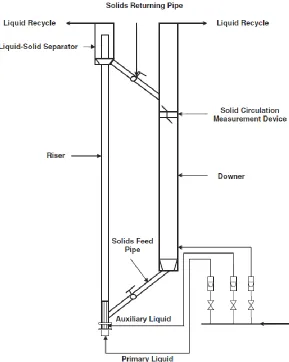
The schematic diagram of the experimental setup is presented in Fig 2.1. It consists of two
main sections: riser and downer. The riser is made of Plexiglas with 5.4m in height and
0.0762m in diameter, and the downer is made of Plexiglas as well with 5.05m in height
and 0.2m in diameter. The liquid-solid separator is located at the top of the riser for
separating the entrained solids from the liquid and the solids circulation rate measurement
device is located near the top of the downer. At the bottom of the riser, there are two liquid
distributors, the seven primary liquid distributors occupy 19.5% of the cross-sectional area,
and the auxiliary liquid distributor which is a porous plate with 4.8% of opening area and
controls the recirculating particles flow rate.
The particles are injected from the solids feed pipe, by adjusting the auxiliary liquid flow
rate, the quantity of recirculating particles from the storage vessel can be controlled. When
auxiliary liquid velocity is zero, there will be no particles enter the riser. Introducing the
auxiliary liquid flow to start feeding particles and with the lifting effect from both auxiliary
liquid and primary liquid, all particles can be fluidized and entrained out of the riser. Then
they are separated from the liquid in the liquid-solid separator, and ejected into the downer,
Figure 2.1: Experimental setup of the LSCFB riser
In this study, two different operating conditions with spherical glass beads operated by
Razzak [1] are selected to study the effects of different drag models, near wall treatments,
specularity coefficient and restitution coefficient, and one operating condition with
irregular plastic beads from Sang [32] is chosen to investigate the drag model for irregular
particles. All the simulations are conducted under the ambient temperature and tap water.
The detailed operation conditions and physical properties of the particles and liquid are