© 2014, IJCSMC All Rights Reserved
431
Available Online at www.ijcsmc.com
International Journal of Computer Science and Mobile Computing
A Monthly Journal of Computer Science and Information Technology
ISSN 2320–088X
IJCSMC, Vol. 3, Issue. 12, December 2014, pg.431 – 445
RESEARCH ARTICLE
ENHANCING SECURITY WITH LOW
COMMUNICATION AND PROCESSING OVERHEAD
FOR MULTI-HOP WIRELESS NETWORKS
Mrs. N.Sathya
1, Dr. R.Pugazendi
2 1Department of Computer Science,K.S.Rangasamy College of Arts and Science,Tiruchengode, Tamil Nadu, India
2Department of Computer Science,K.S.Rangasamy College of Arts and Science,Tiruchengode, Tamil Nadu, India l [email protected]; 2 [email protected]
Abstract---- A multi-hop wireless network is a network in which a packet traversed in multiple successive wireless links to reach its destination. It is similar to mobile adhoc networks, but nodes in multi-hop wireless network are fixed. Multi-hop wireless networks can be deployed at less lost and it enlarges the coverage area with limited transmit power, enhance the spectral efficiency and network throughput. But the multi-hop wireless networks are vulnerable to different types of attacks. The selfish nodes in the multi-hop wireless networks do not relay other packets and by utilizing the cooperative nodes to transfer their packets to other nodes. So that the cooperative nodes are overloaded due to the high traffic. In this paper a trust based method is proposed to provide reliable route. Another method is Hybrid cryptographic has been proposed for improving security and reducing the complexity. Finally the SVM classification algorithm is proposed to efficiently classify the fair and cheating reports.
Key Words---Multi-hop wireless network, Trust based method, Hybrid Cryptography, SVM
_____________________________________________________________________________________
I. INTRODUCTION
In multi hop wireless networks (MWNs), the traffic originated from a node is usually relayed through the other nodes to the
destination for enabling new applications and enhancing the network performance and deployment [3]. MWNs can be deployed
readily at low cost in developing and rural areas. Multi hop packet relay can extend the network coverage using limited transmit
power, improves area spectral efficiency, and enhance the network throughput and capacity. MWNs can also implement many
useful applications such as data sharing [1] and multimedia data transmission. For example, users in one area (residential
neighborhood, university campus, etc.) having different wireless-enabled devices, e.g., PDAs, laptops, tablets, cell phones, etc.,
can establish a network to communicate, distribute files, and share information. However, the assumption that the nodes are
willing to spend their scarce resources, such as battery energy, CPU cycles, and available network bandwidth, to relay others’
packets without compensation cannot be held for civilian applications where the nodes are autonomous and aim to maximize
© 2014, IJCSMC All Rights Reserved
432
Selfish nodes will not relay others’ packets and make use of the cooperative nodes to relay their packets, which degrades
the network connectivity and fairness. The fairness issue arises when the selfish nodes make use of the cooperative nodes to
relay their packets without any contribution to them, and thus the cooperative nodes are unfairly overloaded because the
network traffic is concentrated through them. The selfish behavior also degrades the network connectivity significantly, which
may cause the multi hop communication to fail.
A Report-based payment scheme which is called RACE for MWNs [4]. The nodes submit lightweight payment reports
(instead of receipts) to the AC (Accounting center) to update their credit accounts, and temporarily store undeniable security
tokens called Evidences. The reports contain the alleged charges and rewards of different sessions without security proofs, e.g.,
signatures. The AC (Accounting Center) verifies the payment by investigating the consistency of the reports, and clears the
payment of the fair reports with almost no cryptographic operations or computational overhead. For cheating reports, the
Evidences are requested to identify and evict the cheating nodes that submit incorrect reports, e.g., to steal credits or pay less. In
other words, the Evidences are used to resolve disputes when the nodes disagree about the payment. Instead of requesting the
Evidences from all the nodes participating in the cheating reports, RACE can identify the cheating nodes with submitting and
processing few Evidences. Moreover, Evidence aggregation technique is used to reduce the storage area of the Evidences.
Evidences are submitted and AC applies cryptographic operations to verify the payment only in case of cheating. But the
disadvantage of this method isfewer throughputs, less packet delivery ratio, high latency, less security and high complexity so
we have proposed trust based system, Hybrid cryptographic method and SVM classification to make the payment scheme in an
effective manner. Therefore, reducing the communication and the payment processing overhead is essential for the effective
implementation of the payment scheme and to avoid creating a bottleneck at the AC and exhausting the nodes’ resources.
II. RELATED WORKS
Jianping Pan Et.al proposed Identity-based secure association method in wireless adhoc networks. In the wireless adhoc
networks, the latest technique named as a method of identity-based cryptography is used in 2007. Actually, in the public-key
cryptography schemes, the certificate authorities stored the identity and public key of the entities. This kind of central
authorities is eradicated in the identity-based cryptography method. In this method, the public-key of an entity can be derived
from its identity directly. This feature is crucially significant for ad hoc networks, where public-key infrastructures (PKIs) or
CA hierarchies are also luxurious to build and susceptible to preserve in general. Identity-based cryptography is used to make
possible asymmetric encryption/decryption and signature/verification procedure. It is suggested to utilize Identity-Based
Broadcast Encryption Scheme for better efficiency [2].
Mohamed Elsalih Mahmoud et.al proposed a method which is called practical incentive system to motivate the support of
the nodes in the multi-hop wireless networks in 2010. While the communication sessions may arise without concerning an
infrastructure, the communicating nodes provide digital receipts for the intermediate nodes, which submit the receipts to the
accounting center (AC) to maintain their payment. The decisive point of the practical completion of incentive systems is the receipts’ submission and high overhead because of the high frequency of low-value transactions. If there is a huge number of
receipts is submitted for the node clarification, there are high computation overhead and high complexity. It is suggested that the
© 2014, IJCSMC All Rights Reserved
433
Linu Ann Joy et.al proposed Trusted and Attacker Free Credit Based System called TACS to provide node cooperation,
efficient data transmission, low storage overhead and high performance in 2013. In the new system all the attacker nodes are
removed before beginning the communication and a trust value is assigned to all the nodes. TACS can be used with any source
routing protocol such as Trust based routing protocol, which establishes an end to end connection before transmitting the data.
The results clearly showed that the data transmission in network was fully secured. It improved the security of the system and it
has low communication overhead, processing overhead. It is suggested to replace the hashing techniques with any other
encryption algorithm AES, DES etc for avoiding the attacker to hack the details [7].
Mohamed Taher Nashnosh et.al proposed LESIPT: Lightweight Enhanced Secure Incentive Protocol with Trusted value for
multi-hop wireless networks in 2014. LESIPT signs the digital signatures by the Accounting Center AC and the mobile nodes
require verifying only. The participated nodes save the digital signatures of the sender and then the receiver require using
one-way hash function only. LESIPT reduces the cryptography operations in mobile nodes by the use of conventional digital
signature, and one-way hash function. The results revealed that LESIPT can secure the payment, and improve the network
performance significantly because the verification operation require less time and energy compare to the signing, and the
hashing operations dominate the nodes operations [8].
Mohamed M.E.A et.al proposed Report based payment scheme is used in multi hop wireless networks to motivate node
cooperation, organize packet transmission and implement fairness in 2013. RACE is the payment scheme use the concept of
evidences to protect the payment and need cryptographic operations in clearing the payment only in the case of cheating. The
AC can process the payment reports to know the number of relayed/dropped messages by each node and verify the payment by
investigating the consistency of the node’s reports without submitting and processing security tokens and without false
accusations The results demonstrate that RACE can significantly decrease the communication and processing overhead
comparing to the existing receipt-based payment schemes with acceptable payment clearance delay and Evidences storage
area.It is suggested to implement Hybrid Cryptography for enhance the security and SVM classification algorithm is used for
improving the classification of accuracy [6].
III. Trust Based Method
A node trust value is defined as the degree of belief about the node’s behavior, the expectation, or the probability that a
node will act in a certain way in the future based on the node’s past behavior [5]. Based on sending the packet successfully a
trust value is assigned for each node. The highest trust value is assigned for the nodes that relay messages more successfully.
Similarly, if a node has broken a large percentage of routes in the past, there is a strong belief that this node will break routes
with high probability in the future, and thus the trust based system should avoid it. The trust values are computed to depict the
nodes’ reliability and competence in relaying packets. Based on these trust values, a trust-based system is proposed to route
messages through the highly trusted nodes (which performed packet relay more successfully in the past) to minimize the
probability of dropping the messages, and thus improve the network performance in terms of throughput and packet delivery
© 2014, IJCSMC All Rights Reserved
434
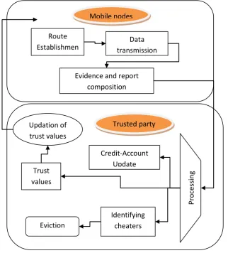
Fig 1: Trust Based System
As shown in the above figure 1 the trust based payment system includes five phases,
The first phase is communication phase. The Communication phase has four processes: route establishment, data
transmission, Evidence composition, and payment report composition/submission. In the route establishment process,
the route is identified and the data is transmitted in the route. In the data transmission process, the source node sends
data packets to the destination node through the established route and the destination node replies with ACK packets.
In the Evidence composition, and payment report composition process, the nodes accumulate the payment reports and
submit them in batch to the TP. This evidence is given to the processing for classify the cheating nodes and normal
nodes.
For the Classifier phase, the TP classifies the reports into fair and cheating. For the Identifying Cheaters phase, the TP
requests the Evidences from the nodes that are involved in cheating reports to identify the cheating nodes. The cheating
nodes are evicted and the payment reports are corrected.
In the Credit-Account Update phase, the AC clears the payment reports.
Mobile nodes
Route
Establishmen
t
Data
transmission
phase
Evidence and report
composition
Trusted party
P
ro
ces
sin
g
Credit-Account
Update
Identifying
cheaters
Eviction
© 2014, IJCSMC All Rights Reserved
435
In the trust value phase, the TP computes the trust values and given the route establishment process. The trust values
are updated at every time interval. These values are given to the route establishment process. Based on the trust values,
the route is selected.
Trust Based System Algorithm
1. Initialize N number of nodes in the network i=1,..N 2. // Route establishment phase
3. S broadcasts RREQ packet to all the nodes //S=source, RREQ includes , , time stamp Ts, Time-to-live (TTL)
4. TP compute the trust value of each node in the network 5. // Establish stable route based on trust value
6. // = depicts the probability that
will relay a packet successfully, =session
7. // = depicts the probability
that will not break a route.
8. // =depicts the node’s ability to
keep a route connected for a minimum number of packets.
9. // Where = is the total number of
sessions participated in, in the last period.
10. // the probability that a packet will reach the destination node through the intermediate nodes Ex: WXYZ=Intermediate nodes
11. If (nodes that relay messages more successfully) 12. Highest trust value
13. Else
14. Lowest trust value 15. End if
16. Select the highest trust nodes
17. Based on the highest trust value select the route and Update the trust values 18. S selects the stable route
19. D composes RREP packet for the first received RREQ packet and reply to S // D=Destination node 20. D create produce the hash chain root //h=hash value
21. // Data transmission phase 22. if ( is the source node) then
23. [ R,X, , Sigs( R,X, , H( ))];
24. Send ( ); // send to the first node in the route 25. Else
26. if(R,X, are correct) and verify (Sigs( R,X, , H( ))) == TRUE) then
27. if( is an intermediate node) then 28. Relay the packet;
29. Store Sigs(R,X, , H( )); 30. End if
31. if( is the destination node) then
© 2014, IJCSMC All Rights Reserved
436
33. End if 34. Else
35. Drop the packet;
36. Send error packet to the source node; 37. End if
38. End if
39. // Evidence and report composition 40. if( is last packet) then
41. Evidence = {R, X, , H( ), , , H ( (R,X, , H( )), (R, , ))};
42. Report = { R, , F,X); 43. Store Report and Evidence; 44. end if
45. // Cheating report identification phase 46. TP: Submit (Reports[ , ));
47. TP : Evidences Request (Ses_ [ , ));
48. TP: Submit (Req_Evs[ , )); 49. TP: Identify_ Cheaters ();
50. TP: Clear the payment of the reports; 51. if ( is honest) then
52. TP : A renewed certificate 53. end if
IV. HYBRID CRYPTOGRAPHY
There are two main phases in the hybrid cryptography method
1. Key generation Phase
In the key generation process, the RSA algorithm is used to generate the keys for all the nodes in the
network. After that the Diffie Hellman algorithm is used for exchanging the keys.
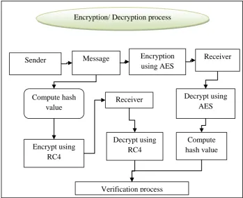
2. Encryption/ Decryption Phase
The RC4 and AES algorithm is used for encryption/decryption process.
AES Algorithm
Sender encrypts the original message by using the AES encryption algorithm. At the receiver side,
the message is decrypted by using the AES algorithm. Again, the hash value is computed for the decrypted
message.
© 2014, IJCSMC All Rights Reserved
437
Fig 2: Hybrid Cryptography Architecture
RC4Algorithm
Hash value of the message is computed. After that, the hash value of the message is encrypted by
using RC4 encryption. At the receiver side, the encrypted hash value of the message is decrypted by using the
RC4 algorithm
Finally these two hash values obtained from AES and RC4 are compared and verified. .
Hybrid Cryptography Algorithm
1. Initialize N number of nodes in the network 2. // Key generation process using RSA algorithm
3. Select the two distinct prime numbers p and q. The integers p and q should be chosen at random, and should be of similar bit-length.
4. Compute // n is used as the modulus for both the public and private keys. Its length, usually expressed in bits, is the key length.
5. Compute
6. Choose a prime number k, such that k is co-prime to z, i.e., z is not divisible by k 7. The values n and k is the public key
8. // Secret key computation process 9. k * a = 1 ( mod z ) // a is the secret key
10. The key is generated for all the nodes in the network
11. // Diffie Hellman Key exchange algorithm
12. Sender and receiver agree to use a prime number p and base g (which is a primitive root modulo 23).
Encryption/ Decryption process
Sender
Message
Encryption
Receiver
using AES
Compute hash
value
Encrypt using
RC4
Decrypt using
RC4
Decrypt using
AES
Compute
hash value
© 2014, IJCSMC All Rights Reserved
438
13. Sender chooses a secret integer a and compute // Sender and receiver 14. Receiver chooses a secret integer b and compute
15. Sender and receiver exchange the values 16. Sender compute the value
17. Receiver compute the value
18. Sender and receiver share a secret value 19. // Encryption and decryption process 20. // AES encryption
21. Sender gives the plain text and change to state
22. Sub-bytes: This is a byte-by-byte substitution. The substitution byte for each input byte is found by using the same lookup table. The size of the lookup table is 16 16.
23. Shift Rows: The Shift Rows transformation consists of (i) not shifting the first row of the state array at all; (ii) circularly shifting the second row by one byte to the left; (iii) circularly shifting the third row by two bytes to the left; and (iv) circularly shifting the last row by three bytes to the left.
24. Mix Columns: This step replaces each byte of a column by a function of all the bytes in the same column. More precisely, each byte in a column is replaced by two times that byte, plus three times the next byte, plus the byte that comes next, plus the byte that follows.
25. Add Round Key: Round key is added to the State using XOR operation 26. // RC4 Encryption
27. Compute the hash value for the message 28. H(M)=hash(M) // Hash value for the message 29. Create two string arrays
30. for (k = 0 to N-1) { 31. i = (i + 1) mod 256; 32. j = (j + S[i]) mod 256; 33. swap S[i] and S[j];
34. t = S[ (S[i] + S[j]) mod 256] 35. C= H(M[k]) XOR t} // Cipher text
36. Where H (M [0...N-1]) is the input message consisting of N bits. 37. // RC4 decryption process
38. For the decryption, XOR the cipher text with the key stream. 39. H(M)=C XOR t
40. // AES Decryption
41. Inverse shift rows: For decryption, the corresponding step shifts the rows in exactly the opposite fashion. The first row is left unchanged; the second row is shifted to the right by one byte, the third row to the right by two bytes, and the last row to the right by three bytes, all shifts being circular. 42. Inverse Sub-bytes: This is a byte-by-byte substitution. The substitution byte for each input byte is
found by using the same lookup table. The size of the lookup table is 16 16. 43. Add Round Key: Round key is added to the State using XOR operation
44. Inverse Mix Columns: This step replaces each byte of a column by a function of all the bytes in the same column. More precisely, each byte in a column is replaced by two times that byte, plus three times the next byte, plus the byte that comes next, plus the byte that follows.
45. The original message is recovered by AES decryption 46. // Compute the hash value of the decrypted message 47. Hash value for the decrypted message 48. // Verification process
49. If( H(M)= ) 50. Successfully verified 51. Else
52. Not successfully verified
© 2014, IJCSMC All Rights Reserved
439
IV. SVM CLASSIFICATIONSupport vector machine (SVM) classification method is used to classify the fair and cheating reports. There are two
phases are
Training phase
Testing phase.
In the training phase, the nodes behavior is computed by using the parameters like packet delivery ratio, signal
strength, traffic flow, time-to-live and compare with the threshold. Then the class labels are assigned to the nodes like cheating
and normal.
In the testing phase, the behavior are analyzed for all the nodes present in the network and find out the cheating nodes
by learning the rules present in training phase. Sometimes, the nodes resources are reduced due to some problems like network
failure, less resources and so on. So, the SNMP (Simple Network Management Protocol) is used to monitoring the network
performance and classify the cheating and normal nodes correctly.
SVM Classification Algorithm Input: Number of nodes
Output: Classification of cheating and normal nodes
1. Initialize N number of nodes in the network
2. // Training phase 3. While
4. Set the SNMP nodes
5. SNMP nodes calculate the energy level 6. // Compute the energy level
7. Calculate transmission energy for all nodes
8. Joules // , I is current in ampere, V voltage in volts, is time
taken to transmit a packet
9. E (p, i) = //
10. Residual energy = Available energy-(Transmission energy +reception energy)
11. // = residual energy of node i
= Available energy in node i, = Amount of energy spent to transmit
the packet from node i to node j , = Amount of energy spent to receive the
packet at node j.
12. Compute the metrics such as packet delivery ratio, signal strength, traffic flow, time-to-live.
13. // Packet delivery ratio –PDR
14.
15. // Signal strength-SS
16. // Where SS=signal strength, =Transmitted signal
strength, =Signal degradation caused by large-scale propagation, =signal
© 2014, IJCSMC All Rights Reserved
440
small-scale propagation 17. //Traffic flow-TF
18.
19. //Time-to-live-TL
20.
21. If ( then //
22. If then / =Threshold for energy 23. Consider as normal nodes
24. Else
25. Consider as cheating nodes 26. End if
27. End if 28. End while
29. Construct classifiers 30. // Testing phase 31. For i=1 to N
32. Compute PDR, SS, TF,TL
33. Learn the rules in the training phase 34. Classify the cheating and normal nodes 35. End for
V. EXPERIMENTAL RESULTS AND DISCUSSION
The performance metrics considered in this work to show the effectiveness of packet delivery ratio, throughput and
end-to-end delay.
Description of performance metrics
1. Packet delivery ratio
It is defined as the ratio of the number of delivered data packet to the destination. This illustrates the level of delivered
data to the destination
.
© 2014, IJCSMC All Rights Reserved
441
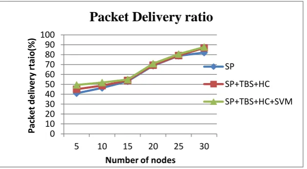
Table 1: Packet delivery ratioPacket delivery ratio (%)
Number of nodes SP SP+TBS+HC SP+TBS+HC+SVM
5
41
45.1
49.4
10
46.4
48.7
51.8
15
53.1
53.9
54.8
20
68.8
69.4
70.9
25
78.8
79.1
80.6
30
82.1
86.8
87.7
Table 1 shows the statistical value for the packet delivery ratio. This shows that if the number of nodes are 30, the
packet delivery ratio for SP is 82.1%, for SP+TSP+HC is 86.8 % and 87.7% for SP+TBS+HC+SVM.
0 10 20 30 40 50 60 70 80 90 100
5 10 15 20 25 30
Pack
e
t
d
e
liv
e
ry
r
taio(%
)
Number of nodes
Packet Delivery ratio
SP
SP+TBS+HC
SP+TBS+HC+SVM
Graph 1: Packet delivery ratio
The above graph 1 clearly shows the packet delivery ratio obtained by the Trust based system, Hybrid Cryptography
and Support Vector machines that achieves higher packet delivery ratio than the Report based payment Scheme (RACE).
2. End-to-End Delay
End-to-end delay is the time it takes a packet to travel across the network from source to destination. Delay
jitter is the fluctuation of end-to-end delay from packet to the next packet.
© 2014, IJCSMC All Rights Reserved
442
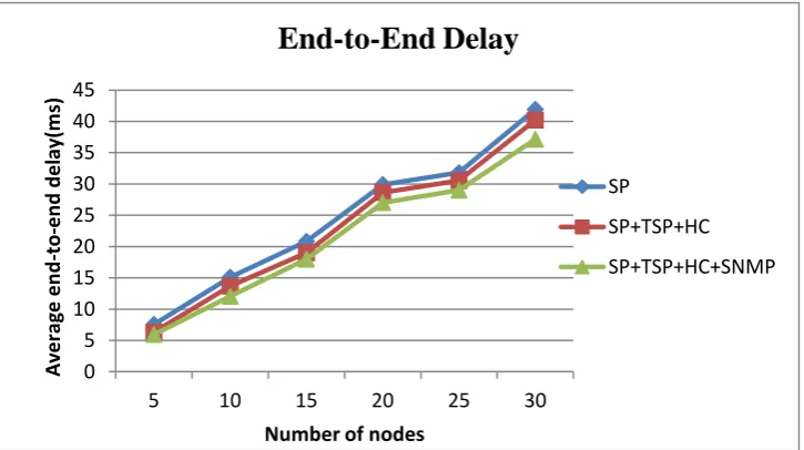
Table 2: End-to-End DelayEnd-to-End Delay (ms)
Number of nodes SP SP+TBS+HC SP+TBS+HC+SVM
5
7.562
6.314
5.957
10
15.101
13.684
12.068
15
20.834
19.014
17.983
20
29.914
28.647
27.034
25
31.824
30.536
29.009
30
41.933
40.214
37.168
Table 2 shows the statistical value for the end delay. This shows that if the number of nodes are 30, the
end-to-end delay for SP is 41.933 ms, for SP+TBS+HC is 40.214 ms and 37.168 ms for SP+TBS+HC+SVM.
0 5 10 15 20 25 30 35 40 45
5 10 15 20 25 30
A
ve
rag
e
e
n
d
-to
-e
n
d
d
e
lay
(m
s)
Number of nodes
End-to-End Delay
SP
SP+TSP+HC
SP+TSP+HC+SNMP
Graph 2: End-to-End Delay
The above graph 2 clearly shows the end-to-end delay obtained by the trust based payment method, hybrid
© 2014, IJCSMC All Rights Reserved
443
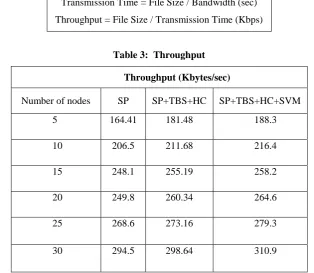
3. ThroughputThroughput or network throughput is the rate of successful message delivery over a communication channel.
Throughput is usually measured in bits per second (bit/s or bps), and sometimes in data packets per second or data packets
per time slot.
Transmission Time = File Size / Bandwidth (sec)
Throughput = File Size / Transmission Time (Kbps)
Table 3: Throughput
Throughput (Kbytes/sec)
Number of nodes SP SP+TBS+HC SP+TBS+HC+SVM
5 164.41 181.48 188.3
10 206.5 211.68 216.4
15 248.1 255.19 258.2
20 249.8 260.34 264.6
25 268.6 273.16 279.3
30 294.5 298.64 310.9
Table 3 shows the statistical value for the throughput. This shows that if the number of nodes are 30, the throughput for
SP is 294.5 Kbytes, for SP+TBS+HC is 298.6 Kbytes and 310.9 Kbytes for SP+TBS+HC+SVM.
0 50 100 150 200 250 300 350
5 10 15 20 25 30
Th
ro
u
gh
p
u
t
(K
b
/s)
Number of nodes
Throughput
SP
SP+TBS+HC
SP+TBS+HC+SVM
Graph 3: Throughput
The above graph 3 clearly shows the throughput obtained by the Trust based payment method, Hybrid cryptography
© 2014, IJCSMC All Rights Reserved
444
VI. CONCLUSION AND FUTURE CONSIDERATIONSA report-based payment scheme is used in multi-hop wireless networks. The nodes submit lightweight
payment reports containing the alleged charges and rewards (without proofs), and temporarily store undeniable security tokens
called Evidences. The fair reports can be cleared with almost no cryptographic operations or processing overhead, and
Evidences are submitted and processed only in case of cheating reports in order to identify the cheating nodes. Based on these
trust values, a trust based System is proposed to route messages through the highly trusted nodes (which performed packet relay
more successfully in the past) to minimize the probability of dropping the messages, and thus improve the network performance
in terms of throughput and packet delivery ratio. In order to enhance the security the Hybrid cryptographic method is used.
SVM classification method is proposed to accurately classify the fair and cheating reports. In future, Energy consumption of
communication systems is becoming a fundamental issue among all the sectors and wireless access networks are largely
responsible for the increase in consumption.
REFERENCES
1. C. Chou, D. Wei, C. Kuo, and K. Naik, “An Efficient Anonymous Communication Protocol for Peer-to-Peer
Applications Over Mobile Ad-Hoc Networks,” IEEE Journal on Selected Areas in Communications, ISSN: 0733-8716,
vol. 25, no. 1, Jan. 2007, pp. 192-203.
2. J. Pan, L. Cai, X. Shen, and J. Mark, “Identity-Based Secure Collaboration in Wireless Ad Hoc Networks,”
International Journal of Computer and Telecommunications Networking, ISSN: 1389-1286, vol. 51, no. 3, Feb. 2007,
pp. 853-865.
3. G. Shen, J. Liu, D. Wang, J. Wang, and S. Jin, “Multi-hop relay for next generation wireless access networks,” Bell
Labs Technical Journal, ISSN: 1089-7089, vol. 13, no. 4, 2009, pp. 175-193.
4. M. Mahmoud and X. Shen, “PIS: A Practical Incentive System for Multi-Hop Wireless Networks,” IEEE Transactions
on Vehicular Technology, ISSN: 0018-9545, vol. 59, no. 8, Oct. 2010, pp. 4012-4025.
5. Mohamed M. E. A. Mahmoud, Xiaodong Lin, and Xuemin (Sherman) Shen, “Secure and Reliable Routing Protocols
for Heterogeneous Multi hop Wireless Networks,” IEEE Transactions On Parallel And Distributed Systems , 2013.
6. M.M.E.A. Mahmoud and Xuemin Shen, “A secure payment scheme with low communication and processing overhead for multi hop wireless networks,” IEEE Transactions on Parallel and Distributed Systems, vol. 24, no. 2, Feb. 2013, pp.
209-224.
7. Linu Ann Joy, Divya T.V, “Trusted and Attacker Free Credit Based System For Multi hop Wireless Networks”,
International Journal of Advanced Research in Computer and Communication Engineering, ISSN: 2319-5940, Vol. 2,
no. 9, sep. 2013.
8. Mohamed Taher Nashnosh and Dr. B Vijaya Babu, “LESIPT: Lightweight Enhanced Secure Incentive Protocol with
© 2014, IJCSMC All Rights Reserved
445
AUTHOR’S BIOGRAPHYMrs. N. Sathya received her M.C.A (Computer Application) degree from Bharathiyar University,
Coimbatore in 2012. She is pursuing M.Phil (Computer Science) degree Under the Supervision of Dr.
R. Pugazendi. Her Area of interest is Networking.
Dr. R. Pugazendi is working as an Associate professor and Head in Department of Computer Science.
He obtained his Ph.D in Computer Science from Periyar University and published numerous research
Papers in International Journals and also presented papers in various National and International