An Efficient Adaptive Clutter Compensation Algorithm for Bistatic
Airborne Radar Based on Improved OMP Application
Cunxiao Ji1, 2, *, Mingwei Shen1, 2, Chao Liang2, Di Wu3, and Daiyin Zhu3
Abstract—In this study, the misalignment of bistatic clutter spectral centers is considered, and an efficient adaptive main-lobe clutter compensation approach is presented for mitigating the bistatic geometry-induced clutter dispersion. In order to reduce computational load, an improved orthogonal
matching pursuit (OMP) is introduced into the space-time clutter spectrum estimation. This
method can accurately extract the required parameters for compensating the clutter spectral centers misalignment via sparse reconstruction with the desired Doppler cells. Simulation results are presented to demonstrate the effectiveness and efficiency of the proposed method.
1. INTRODUCTION
Several research activities are in progress on bistatic radar systems for airborne applications in recent years. Bistatic airborne radar systems offer several advantages over their monostatic counterparts, including far range coverage, strong anti-interference and high security capability. Since the transmitter (TX) and receiver (RX) motions yields a non-stationary behavior of the clutter spectrum, a bistatic airborne radar system must effectively cope with severe spectrally diverse clutter returns.
Brennan and Reed proposed a concept of space-time adaptive processing (STAP) [1, 2] in 1973, which can improve the monostatic airborne radar moving target detection performance remarkably. STAP has become an advanced technique and is considered as a powerful tool for monostatic airborne radar detecting moving target and suppressing ground clutter. However, it is difficult to apply the STAP approach to bistatic airborne radar in practice because of strong non-stationary behavior of the clutter spectrum [3].
In the last few years, a number of contributions have been proposed, and the problem of clutter range dependence is largely addressed. Among them, there are some effective approaches to limit the effect of monostatic clutter range dependence such as Doppler wrapping (DW) [4], angle-Doppler compensation (ADC) [5, 6], and adaptive angle-Doppler compensation (AADC) [7]. An extension of AADC algorithm for bistatic STAP is also presented [8] to compensate for the spectral centre (SC) misalignment and angel-Doppler trajectory slope variability over range. However, the compensation parameters of DW and ADC are sensitive to system error. The required parameters of the AADC and adaptive FO-ADC approach are obtained by the minimum variance (MV) estimation of the clutter spectrum using a sub-aperture smoothing approach, which results in a great increase of computational load and limits real-time processing.
In this paper, an improved OMP [9] approach is employed to obtain both main-lobe clutter spectrum estimation and the required compensation parameters for clutter SC. It is shown that the
Received 8 June 2017, Accepted 15 August 2017, Scheduled 22 August 2017 * Corresponding author: Cunxiao Ji ([email protected]).
1 College of Computer and Information Engineering, Hohai University, Nanjing 211100, China. 2 Science and Technology on
204 Ji et al.
SC can be estimated accurately from the data themselves. In contrast to the reduced-dimension sparse reconstruction (RDSR) [10–12], the presented method can significantly reduce the computational load. The rest of this paper is organized as follows. In Section 2, we first analyze the range dependence clutter dispersion of bistatic airborne radar system. Section 3 is devoted to the clutter spectrum sparse reconstruction using the improved OMP and the main-lobe clutter compensation. The validity of the method is confirmed by the simulation experiment in Section 4. Finally, a brief conclusion is drawn in Section 5.
2. PROPERTIES OF BISTATIC AIRBORNE RADAR CLUTTER
The receiving system under consideration is a pulse Doppler radar residing on an airborne platform. The
RX antenna is a uniform linear array (ULA), which consists of N elements with inter-element spacing
d. Each of these elements receives K echoes from a transmitted train of K coherent pulses during the
coherent processing interval (CPI) with wavelength λ and pulse repetition frequency (PRF). The TX
and RX platforms are at the altitudes of Ht and Hr, and vt and vr are the TX and RX platforms’
speeds, respectively.
Without loss of generality, the bistatic airborne radar geometry is shown in Fig. 1. The coordinate
system is assumed that the x-axis is aligned with the RX flight direction; β2 represents the TX flight
direction; points O and Q stand for the projections of the RX and TX on the ground with distance
Dtr; β1 represents the angle between OQ and x-axis. Point P stands for one scatterer in the scenario
of interest; Rt is the distance between TX and P;Rr is the distance between RX and P, respectively.
We assume that the TX and RX work in sync for the convenience of using STAP technology. For the
convenience of discussion, in this article, we deal with only one such configuration β1 =β2 = 0.
Figure 1. Geometry of bistatic airborne radar.
As well known, the Doppler frequency associated to each scatterer is only dependent on the scatterer position and the antenna geometry and motion [1]. In the case of a bistatic airborne radar system, the clutter trajectory [3] in angle-Doppler domain can be given by:
fd= vt
λ cosθtcosϕt+ vr
λ cosθrcosϕr (1)
whereθtand ϕtrepresent TX azimuth angle and elevation angle, andθr and ϕr represent RX azimuth
angle and elevation angle, respectively. For the main-lobe clutter, we assume that θtmain = π2, so that
formula (1) can be simplified to the formula below:
fd= vr
(a) (b)
(c)
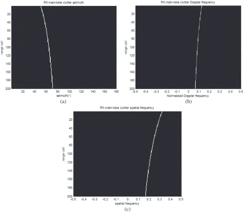
Figure 2. θrmain, Doppler frequency and spatial frequency in different range cells. (a) θrmain. (b) Doppler frequency. (c) Spatial frequency.
Considering N = 16 elements and K = 64 pulses in one CPI, for the RX, the trajectories of θrmain,
Doppler frequency and spatial frequency corresponding to 200 range cells are depicted in Fig. 2(a), Fig. 2(b) and Fig. 2(c). It is apparent thatθtmain and θrmaindo not overlap, θrmain varies fast in short-range clutter area. In remote areas, the trend is slow. The Doppler frequency and spatial frequency of the RX main-lobe clutter vary with range cells as well. The bistatic airborne clutter is range dependence non-stationary.
3. ESTIMATION OF MAIN-LOBE CLUTTER SPECTRUM AND SC COMPENSATION
206 Ji et al.
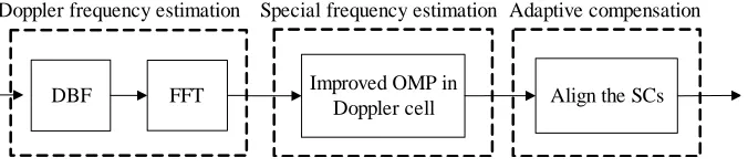
DBF FFT Improved OMP in
Doppler cell Align the SCs Doppler frequency estimation Special frequency estimation Adaptive compensation
Figure 3. The EAADC flowchart.
AADC. With reference to [11, 12], the implementation of the presented efficient adaptive angle-Doppler compensation (EAADC) strategy is summarized in the following steps and sketched in Figure 3.
3.1. Estimation of Main-Lobe Clutter Doppler Frequency
The received data Xl from theN-element array for thel-th range gate can be reshaped into aN ×K
matrix as
Xl= [ Sl1 Sl2 . . . Sl K ]N×K (3)
where Sl i represents the spatial snapshot vector from the N-element array for the l-th pulse of a K
-pulse CPI. The received sum beam output can be derived via digital beam forming (DBF) and can be transformed to the Doppler domain via Fourier Transform, which can be implemented as
DΣ,l =wΣ,lXlFHΣ,D = [ DΣ,l1 DΣ,l2 . . . DΣ,l K ] (4)
where wΣ,l denotes the spatial weight of sum beam; FΣ,D comprises the Fourier Transform weights;
the superscript (H) denotes complex conjugate transpose; D
Σ,l i represents the output of the i-th sum beam Doppler cell. As a consequence, the main-lobe clutter Doppler frequency can be determined by the peak value ofDΣ,l.
3.2. Estimation of Main-Lobe Clutter Spatial Frequency
If we still utilize fast Fourier Transformation (FFT) to obtain the angle spectrum in the spatial domain, the bistatic clutter spectrum will suffer from main-lobe broadening, high side-lobe leakage, etc., which consequently lead to a poor estimation of the spatial frequency. To obtain high-resolution spectral
estimation, sparse reconstruction (SR) is utilized to estimate the clutter spectrum. However, the
implementation of SR in the angle-Doppler domain requires complex multiplications [13, 14], which is impractical. Compared with two-dimensional SR in the angle-Doppler domain, an RDSR algorithm was proposed in [11, 12], and the RDSR based on convex optimization also has a high computational cost, which limits its real-time processing.
In this paper, an improved OMP technique is utilized to reduce the computational load, and only the array output corresponding to the main-lobe clutter is recovered in the spatial domain. Therefore, the angle spectrum can be achieved:
σˆ
l i,max= argminσl i,max1
s.t. Dl i,max−Miσl i,max2 ≤δi
(5)
where·1 stands for theL1 norm,·2 theL2 norm,Dl i,maxthe Doppler-element data corresponding
to the maximum Doppler cell of thel-th range gate,σl i,maxthe estimated clutter distribution response
in spatial domain, Mi an over complete basis representation in terms of all possible sources locations,
μj thej-th column of Mi, andδi the error allowance related to Dl i,max.
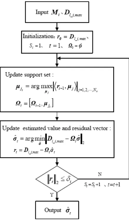
The flowchart of the improved OMP is shown in Fig. 4 for the maximum Doppler cell of thel-th
range gate. To apply the OMP with the unknown sparsity situation, firstly the initial value Sl of the
sparsity is set to 1. Then the column μj, which has the max-relativity with the residual vector rt, is
selected from Mi:
μjt = arg maxμ
φ
Figure 4. Flowchart of the improved OMP algorithm.
Sequentially we can obtain the corresponding support setΩt= [Ωt−1,μjt]. Consequently, the scattering
coefficients of main-lobe clutter spectrum can be recovered efficiently, and the residual vector can be updated as follows:
ˆ
σt= arg min
σ
Dl i,max−Ωtσt2 =
ΩHt Ωt−1ΩHt Dl i,max
rt=Dl i,max−Ωtσˆt
(7)
The reconstruction process ends when rt2 ≤ δi. Otherwise, Sl will increase and continue iterating,
and finally, the value of the sparsity is Sl,max by the end of the reconstruction process. Applying this
procedure repeatedly for all L range gates, we can obtain the high-resolution two-dimensional (2D)
spectral distribution of the bistatic main-lobe clutter. Due to the spectrum discontinuity of SR via the improved OMP in the spatial domain, the spectral centre frequency estimation method in the reference [15] is also employed to obtain the peak of main-lobe clutter in spatial domain.
3.3. Adaptive Compensation of the Spectral Centers
208 Ji et al.
We assume that the estimated SC of the reference range cell is (fs0, fd0), and the SC of thel-th range cell is (fs l, fd l). The SC displacements in terms of the spatial frequency Δfs l and normalized Doppler frequency Δfd l are as follows:
Δfs l = fs l−fs0 (8)
Δfd l = fd l−fd0 (9)
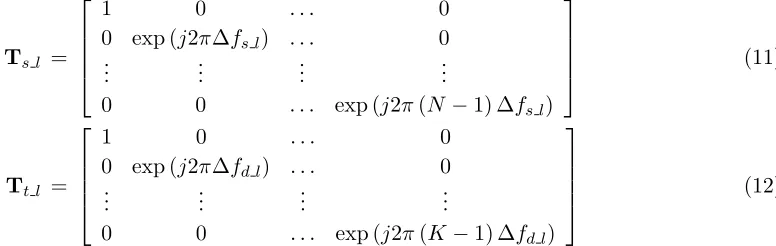
We can apply a complex linear phase taper over both angle and Doppler dimensions to compensate for the SC migration, which can be expressed as
Cl=Ts lXlTt l (10)
whereTs l and Tt l are the compensation factor in the spatial domain and compensation factor in the
Doppler domain, respectively. They can be expressed as:
Ts l =
⎡ ⎢ ⎢ ⎢ ⎣
1 0 . . . 0
0 exp (j2πΔfs l) . . . 0
..
. ... ... ...
0 0 . . . exp (j2π(N −1) Δfs l)
⎤ ⎥ ⎥ ⎥
⎦ (11)
Tt l =
⎡ ⎢ ⎢ ⎢ ⎣
1 0 . . . 0
0 exp (j2πΔfd l) . . . 0
..
. ... ... ...
0 0 . . . exp (j2π(K−1) Δfd l)
⎤ ⎥ ⎥ ⎥
⎦ (12)
The STAP performance can be significantly improved owing to the reduction of the bistatic clutter dispersion by applying the aforementioned implementation to the secondary data before covariance
estimation. The improvement factor (IF), given as the ratio of output SINR to the input SINR,
is presented to evaluate the effectiveness of the proposed method as well as the performance of the mitigating the bistatic clutter dispersion with a reduced-dimension (RD) STAP approach [16]. The detailed analysis will be given in Section 4.
4. SIMULATION RESULTS AND ANALYSIS
This section is devoted to illustrating the performance of the fast implementation of spectral estimation via improved OMP and clutter compensation for bistatic airborne radar using the simulated data. In
the simulation, consider RX antenna withN = 16 elements andK= 64 pulses in one CPI. The bistatic
airborne radar system parameters are listed in Table 1.
Table 1. Simulation parameters for bistatic airborne radar.
PRFfr 4200 Hz
Bandwidth fs 2 MHz
Element spacing and wavelength ratio 0.5
TX platform height Ht 10 km
RX platform height Hr 6 km
The distanceDtr 10 km
TX main-lobe θtmain 0.5π
The angle β1 0
The angle β2 0
TX Platform velocity vt 150 m/s
Normalized Doppler frequency N o rm al iz ed s pat ia l f requ e nc y
-0.5 0 0.5
-0.5 -0.4 -0.3 -0.2 -0.1 0 0.1 0.2 0.3 0.4 0.5 -50 -45 -40 -35 -30 -25 -20 -15 -10 -5 0
Normalized Doppler frequency
Nor m a liz e d s p at ial f requ enc y
-0.5 0 0.5
-0.5 -0.4 -0.3 -0.2 -0.1 0 0.1 0.2 0.3 0.4 0.5 -50 -45 -40 -35 -30 -25 -20 -15 -10 -5 0 Normalized Doppler frequency
N o rm al iz ed s p at ia l f re q ue nc y
-0.5 0 0.5
-0.5 -0.4 -0.3 -0.2 -0.1 0 0.1 0.2 0.3 0.4 0.5 -60 -50 -40 -30 -20 -10 0 (a) (b) (c)
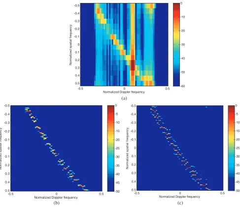
Figure 5. The clutter angle-Doppler spectrum image of the 150th range cell. (a) 2D FFT. (b) Spatial RDSR. (c) Improved OMP.
-0 .5 0 0. 5 -0 .5 0 0. 5 10 0 15 0 20 0 25 0 ra nge c e ll
Normalized Doppler frequency Normalized spatial frequency
210 Ji et al.
-0.5
0
0.5
-0.5 0
0.5 100 150 200 250
Normalized spatial frequency Normalized Doppler frequency
ra
n
g
e
c
e
ll
-0.5
0
0.5
-0.5 0
0.5 100 150 200 250
Normalized spatial frequency Normalized Doppler frequency
ra
n
ge c
e
ll
(b) (c)
Figure 6. SCs migration over range. (a) Before compensation. (b) RDSR with AADC. (c) Improved OMP with AADC.
-0.5 -0.4 -0.3 -0.2 -0.1 0 0.1 0.2 0.3 0.4 0.5 10
20 30 40 50 60 70 80
Normalized Doppler frequency
IF
(d
B)
original data RDSR,AADC Improved OMP,AADC
Figure 7. IF of the RD STAP after compensation.
The bistatic spectrum obtained via 2D FFT of the 150th range cell is shown in Fig. 5(a). To evaluate the performance of the improved OMP in the spatial domain, the angle-Doppler spectrum obtained by using the improved OMP in each Doppler cell with the simulation parameterδi= 101Dl i,max2is shown in Fig. 5(c). For comparison purpose, the sparse reconstructed spectrum obtained via RDSR is also provided in Fig. 5(b). It is clear that Fig. 5(b) has much better resolution than Fig. 5(c). However, Fig. 5(c) has much better resolution and lower side-lobe level than that of 2D FFT as well, which will also improve the accuracy of estimating the SC location of bistatic main-lobe clutter.
the SCs of the spectral traces are exactly co-located.
Figure 7 presents the IF curves obtained after applying the improved OMP and the RDSR in conjunction with AADC approach to the secondary data, where the 150th range cell is selected as the reference cell. Two SR methods together with AADC yield reduced bistatic clutter power dispersion with respect to the case of without compensation. Thus, an improvement of 6.04 dB and 6.58 dB can achieved around SC after compensation, respectively.
To complete our analysis, the complex multiplications of bistatic main-lobe clutter spectrum
estimation using RDSR and the improved OMP are calculated. For L range cells bistatic
main-lobe clutter spectrum estimation, the former is about O[Ns2N L] while the latter is about
L
l=1
O[NsNSl,max
(1+Sl,max)
2 ], whereNs=ρsN and considering the angle resolution scale ρs= 8. From the
simulation, the averageSl,maxof allLrange cells is aboutSl= 4, so the total complex multiplications for the improved OMP implementation is O[NsNSl(1+2 Sl)L]. In consequence, the complex multiplications for the improved OMP in this paper is significantly better than that for the RDSR since the former is about 7.81% of the latter. It can be found that the improved OMP together with AADC offers a good tradeoff between SCs compensation and complex multiplications. These two methods with AADC usually yield comparable performance, with one of them being definitely the best one.
5. CONCLUSION
This work describes an improved EAADC to mitigate the range dependence clutter dispersion for bistatic airborne radar system. We use the improved OMP method to calculate the requisite spatial frequency within the main-lobe clutter Doppler cells for realigning the spectral center instead of the RDSR, so the complex multiplications is dramatically reduced. The performance of the EAADC has been demonstrated against synthetic data showing that this method offers a good tradeoff between SCs compensation and complex multiplications. Therefore, this method is more suitable for bistatic airborne radar real-time processing.
ACKNOWLEDGMENT
This work was supported in part by the National Natural Science Foundation of China (No. 61201459, No. 61301212), Science and Technology on Electronic Information Control Laboratory and China Scholarship Council (No. 201606715009).
REFERENCES
1. Klemm, R., Principles of Space-time Adaptive Processing, 1–116, The Institution of Electrical
Engineers, London, United Kingdom, 2002.
2. Brennan, L. E. and I. S. Reed, “Theory of adaptive radar,”IEEE Transactions on Aerosp. Electron.
Syst., Vol. 9, No. 2, 237–252, Mar. 1973.
3. Meng, X. D., J. X. Wu, T. Wang, et al., “Clutter analysis and range-ambiguous clutter suppression
for bistatic airborne radar,” Journal of Xidian University, Vol. 35, No. 6, 992–998, 2008.
4. Borsari, G. K., “Mitigating effects on STAP processing caused by an inclined array,” Proceedings
of the Radar Conference, 1998, Radarcon 98, 135–140, IEEE, 1998.
5. Zhao, J. and Z. D. Zhu, “A multiple space angle compensation method for airborne radar with
non-side-looking uniform linear array,” Acta Aeronaut Astronaut Sin, Vol. 31, No. 11, 2216–2221,
2010.
6. Fallah, A. and H. Bakhshi, “Extension of Adaptive Angle-Doppler Compensation (AADC) in STAP
to increase homogeneity of data in airborne bistatic radar,” Sixth International Symposium on
Telecommunications, 367–372, IEEE, 2013.
7. Tian, B., D. Y. Zhu, and Z. D. Zhu, “A fast adaptive angle Doppler compensation method,” Acta
212 Ji et al.
8. Colone, F., “Spectral slope-based approach for mitigating bistatic space-time adaptive processing
clutter dispersion,” IET Radar Sonar& Navigation, Vol. 5, No. 5, 593–603, 2011.
9. Wang, J., S. Kwon, and B. Shim, “Generalized orthogonal matching pursuit,”Mathematics, Vol. 60,
No. 12, 6202–6216, 2014.
10. Shen, M. W., J. Wang, D. Wu, et al., “An efficient data domain STAP algorithm based on
reduced-dimension sparse reconstruction,” Acta Electronica Sinica, Vol. 42, No. 11, 2286–2290, 2014.
11. Shen, M. W., J. Yu, D. Wu, et al., “An efficient adaptive angle-doppler compensation approach for
non-sidelooking airborne radar STAP,”Sensors, Vol. 15, No. 6, 13121–13131, 2015.
12. Wang, J., M. W. Shen, D. Wu, et al., “An efficient STAP algorithm for nonsidelooking airborne
radar based on mainlobe clutter compensation,”Journal of Radars, Vol. 3, No. 2, 235–240, 2014.
13. Wu, H. and S. Wang, “Adaptive sparsity matching pursuit algorithm for sparse reconstruction,”
IEEE Signal Processing Letters, Vol. 19, No. 8, 471–474, 2012.
14. Gurbuz, A. C., V. Cevher, and J. H. Mcclellan, “Bearing estimation via spatial sparsity using
compressive sensing,”IEEE Transactions on Aerospace &Electronic Systems, Vol. 48, No. 2, 1358–
1369, 2012.
15. Wu, H., Y. L. Wang, and J. W. Chen, “Nonhomogeneous detector for STAP based oil spectral
center frequency method,” Journal of Systems Engineering and Electronics, Vol. 30, No. 4, 606–
608, 2008.
16. Wang, Y. L., Y. N. Peng, and Z. Bao, “Space-time adaptive processing for airborne radar with
various array orientations,” IEE Proceedings — Radar, Sonar and Navigation, Vol. 144 No. 6,