Mesh-based isolated micro inverter based on the
Quasi-Z-Source network
Ramesh Vallamshetla & Leela Kumari Ch
Assistant Professor, EEE Bandari Srinivas institute of technology, Chevella, Rangareddy,
ramesh.vallamshetla@gmail.com
Assistant Professor, EEE Bandari Srinivas institute of technology, Chevella, Rangareddy,
leesmileschalla@gmail.com
Abstract—Due to many benefits quasi-Z-source based converters are suitable for renewable energy application, in particular for the photovoltaic systems. However, there are some problems that need closer analysis before quasi-Z-source converter can be fully implemented in PV micro inverters. The goal of this work is to address those problems and achieve stable performance of a micro inverter based on the quasi-Z-source network in the full load profile. The simulation results confirm the feasibility of the suggested solution. Tuning process is revealed.
Keywords—PV, micro inverter, quasi-Z-source converter, Mesh connection, SOGI, Proportional-Resonance controller.
I. INTRODUCTION
Recently Z-Source Inverters (ZSIs) and quasi-Z-Source Inverters (qZSIs) have been proposed for various fields of applications. ZSIs and qZSIs overcome the limitation of the conventional inverters. They can buck and boost voltage and do not suffer from Shoot-Through (ST) states. Also, qZSI has Continuous Input Current (CIC) from the source and shares a common ground with a dc-source, which is suitable for renewable energy application (in particular for the Photovoltaic (PV) systems). These inverters are capable of performing Maximum Power Point Tracking (MPPT) without extra dc-dc converter in the wide range of input voltage.
At the same time, there are not many papers devoted to the study of the Mesh-connected qZSI, especially for single-phase micro inverter application.
should be solved. It is well known that idle mode in the load of the any type boost converter leads to the discontinuous conduction mode and over boost performance. Resonance phenomena inherited from the qZS network complicates this issue. In advance, low frequency power ripple caused by single-phase ac system leads to the input current fluctuation that is identical to the variable dc load. The problem is that most of the above mentioned papers cover the study only in a very certain points. The main goal of this work is to achieve stable performance of the micro inverter based on qZS network with galvanic isolation connected to the Mesh in the full load profile.
II. CONVERTER TOPOLOGY
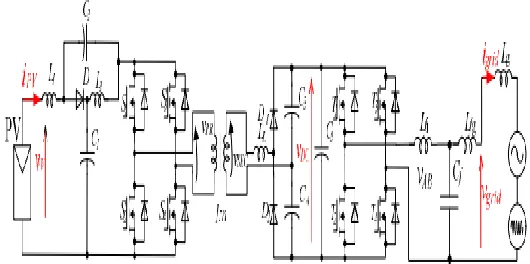
Fig. 1.Galvanically isolated dc-dc converter based on qZS network and serial resonance.
The wide regulation range allows one to extract more power even if the sun irradiation is poor. The main parameters of the converter are presented in Table I.
TABLE I. PASSIVE COMPONENTS USED FOR SIMULATION MODEL
III. CONTROL STRATEGY
Fig. 2 shows the overall control system of the Meshconnected galvanically isolated qZS based micro inverter. It consists of MPPT, Phase-Locked-Loop (PLL) and a proportional-resonance regulator
(PR) with harmonic compensation (HC) block and a dc-link voltage control loop with nonlinear PI controller .
qZS capacitors C1, C2 2.64 µF qZS inductors L1,. L2 11.6 µH Magnetizing inductance LM 500 µH Resonant inductance LRes 0.4 µH Resonant capacitors C3, C4 48 nF Dc-link capacitor C5 180 µF Capacitance of the filter capacitor
Cf
0.47 µF
Inductance of the filter inverter side inductor Li
1.5 mH
Inductance of the filter Mesh side inductor Lg
0.7 mH
Fig. 2. The control system of the micro inverter: control strategy for Mesh connection (a), dc-link control strategy(b), PR regulator (c).
A. MPPT
A solar cell may operate over a wide range of voltages and currents. The U/I characteristic has nonlinear profile and a special algorithm is needed for the MPPT. There are two algorithms commonly used for MPPT : the Perturb and Observe (P&O) method, and the incremental conductance method. In current project the P&O method was selected due to its simplicity. The P&O method operates by periodically incrementing or decrementing the current reference based on the measured input power. If a given perturbation leads to an increase (decrease) in the output power of the PV module, the subsequent perturbation is generated in the same (opposite) direction. The MPPT block gives current amplitude IMAX for the Mesh current reference (iREF), as indicated in Fig. 2a.
voltage. The PLL outputs a unity sinus signal, which is synchronous with the Mesh voltage (VMesh) fundamental harmonic. The PLL is based on the second order generalized integrator (SOGI) algorithm. It is chosen among others due to the pure and stable sinusoidal output signal despite on the distorted Mesh voltage waveform .
C. Mesh control
PR regulator is shown in Fig. 2c. The PR regulator output is given to the Sinusoidal Pulse Width Modulator (SPWM) of VSI.
D. DC-link
voltage control The qZS converter is regulating the dc-link voltage. To provide required
Mesh injected current quality, the dc-link voltage should be stable with minimum ripple. The dc-link control is separated from Mesh connection control strategy, as shown in Fig. 2b. It is based on the nonlinear PI algorithm, as shown in Fig. 3. The output of the dc-link controller is the modulation signal (Ds) of the qZS converter.
Fig. 3. Non linear PI regulator for dc-link voltage control.
It can be seen that limiters are used for each components of the regulator. Proportional limiters are set in a range from -2 V to +2 V. Also nonlinear integral is used. In particular it has different time constants for positive and negative voltage error VERROR. Proportional coefficient and time constant of PI controller is selected using approach described. In order to avoid any overregulation phenomena, the simple nonlinearity is introduced, as indicated in Fig. 3. The qZS converter is operating in dual modulation mode. Low input voltage values 10…35 V are boosted by using ST state and high input voltage values 35…60 V are stepped down by utilizing Phase Shift Modulation (PSM). As a result extended operation voltage range is achieved. The ST states are created by the overlap of active states. The PSM is achieved by shifting control signals towards each other so that the resulting active state is reduced Error! Reference source not found..
The startup routine of the micro inverter is divided into three phases as follows:
1. Input voltage appears at the input terminals i.e. PV panel is connected or it starts producing power. The converter goes to standby state and scans the system for errors.
2. The link regulator starts to regulate dc-link voltage VDC (Fig. 1) and PLL is trying to synchronize with the Mesh. Also MPPT algorithm is started in this mode.
3. Mesh connection and power injection to the Mesh. This state will be activated only after the dc-link voltage has reached a value that is close to the nominal and the PLL has stable synchronization.
IV. SIMULATION RESULTS
The microinverter was simulated using PSIM software. The simulation parameters are shown in Table II. In particular it shows all parameters of the regulators.
TABLE II VALUES USED FOR SIMULATION STUDY
Parameter Unit Value
Mesh RMS voltage (V) 230
Input voltage (V) 30
PI(Ti)(positive) (s) 2
PI(Ti)(negative) (s) 0.2
PR (KRES) 4000 Switching frequency (kHz) 100
Output power (W) 240
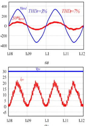
The simulation results are shown in Fig. 4 and Fig. 5. Fig. 4 shows steady-state mode while the Fig. 5 shows the transient response. In steady state mode the Mesh current waveform is close to the sinusoidal shape and in phase with the voltage, as shown in Fig.
4a. The THD of the Mesh current is 7 % while the voltage hazes only 3 %. The higher THD is caused by higher level harmonics, which are present in the current.
Fig. 4. Steady state simulation of the microinverter: Mesh voltage and current (a), input voltage and input current (b).
The input voltage of the micro inverter was 30 V and average current 8.3 A. The 100 Hz current ripple appear at the input, as indicated in Fig.4b. Fig. 5 shows gird connection transient at the time instant 0.3s. The transient response settles down within 5 periods of the Mesh voltage i.e. 0.1 s. The Mesh connection results in some current spikes, as shown in Fig. 5a. These spike is caused by charging dc-link
capacitors from the Mesh side, which can be eliminated by means of passive components. At the same time the duration and amplitude (about 12 A) of those spike is negligible and it will not damage semiconductors. The transient is not affecting the PLL, as indicated in Fig. 5b. The q and d components are not changed.
VI. ACKNOWLEDGEMENT
Fig. 5. Transient responds of the micro inverter: Mesh current and voltage (a), d and q components of the Mesh voltage (b).
V. CONCLUSIONS
This paper presents general description of the galvanically isolated micro converter based on the qZS network. The control system consists of MPPT, SOGI PLL and the PR regulator and a dc-link voltage control loop with nonlinear PI controller. Simulation results showed that relatively simple approach allow achieving stable performance. This control strategy can be implemented on a low cost microcontroller, which will make this solution attractive for the industry. Further work of the team is directed to the experimental realization of the described concept.
REFERENCES
[1] F.Z. Peng, “Z-Source Inverter,” IEEE Trans. Ind. Applicat., vol. 39, no. 2, pp. 504-510, Mar./Apr. 2003.
[2] J. Anderson, F.Z. Peng, “Four quasi-Z-Source inverters,” IEEE Power Electronics Specialists Conference, PESC'08, pp. 2743-2749, 15-19 June 2008.
[3] D. Vinnikov, I. Roasto, “Quasi-Z-Source-Based Isolated DC/DC Converters for Distributed Power Generation,” IEEE Trans. Ind. Electron., Vol. 58, no. 1, pp. 192-201, Jan. 2011.
[4] Yan Zhou, Hongbo Li, Hui Li, “A Single-Phase PV Quasi-Z-Source Inverter With
Reduced Capacitance Using Modified Modulation and Double-Frequency Ripple Suppression Control” IEEE Trans. Power Electron., vol. 31, no.3, pp. 2166-2173, 2016. [5] O. Husev, S. Stepenko, C. Roncero-Clemente, E. Romero-Cadaval, R. Strzelecki, “Experimental investigation of high frequency 3L-NPC qZS inverter for photovoltaic application”, in Proc. 39th Annual Conf. IEEE Industrial Electronics Society (IECON 2013), Vienna, Austria, 2013, pp. 5967–5972.
[6] O. Husev, L. Liivik, F. Blaabjerg, A. Chub, D. Vinnikov, I. Roasto. “Galvanically Isolated Quasi-Z-Source DC-DC Converter with a Novel ZVS and ZCS Technique”, IEEE Trans. Ind. Electron., vol 62, no 12, pp. 7547-7556, 2015. [7] A. Battiston, E.H. Miliani, S. Pierfederici, F. Meibody-Tabar, F. “A Novel Quasi-Z-Source Inverter Topology With Special Coupled Inductors for Input Current Ripples Cancellation”, IEEE Trans. Power Electron., vol. 31, no.3, pp. 2409-2416, 2016.
[8] L. Yushan., H. Abu-Rub., G. Baoming. “Z-source/quasi-Z-source inverters: derived networks, modulations, controls, and emerging applications to photovoltaic conversion“ IEEE Industrial Electronics Magazine, Vol. 8, No. 4. pp. 32-44, Dec. 2014.
Connected PV Power Generation Using a Quasi-Z-Source Inverter”, JPE, Vol. 10, No. 1, January 2010, pp 79-84.
[10] L. Yushan, G. Baoming, H. Abu-Rub, F.Z. Peng “Control System Design of Battery-Assisted Quasi-Z-Source Inverter for Mesh-Tie Photovoltaic Power Generation”, IEEE Trans. Sustainable Energy, Vol. 4, no.4, pp. 994-1001 [11] L. Yuan, F.Z. Peng, J.G. Cintron-Rivera, S. Jiang, “Controllerdesignforquasi-Z-sourceinverterinphotovoltaicsystems”, Energy Conversion Congress and Exposition (ECCE), 2010 IEEE, pp: 3187 – 3194.
[12] S.M, Dehghan, E.Seifi, M. Mohamadian, R. Ghareh Khani,“Mesh connected DG systems
based on Z-source NPC inverters”. In Proc. of Power Electronics, Drive Systems and Technologies Conference (PEDSTC), 2011, pp. 104-110. [13] T. Chandrashekha, M. Veerachary, “Control of single-phase Z-source inverter for aMesh connected system”, in Proc. of Power Systems, 2009. ICPS '09. International Conference on, pp. 1-6.