FPGA-Based Approach to Level-1 Track Finding at CMS for the
HL-LHC
LouiseSkinnari1,afor the CMS Collaboration
1Cornell University, Ithaca, NY, USA
Abstract. The high luminosity upgrade of the LHC is expected to deliver luminosities of 7.5×1034cm−2s−1, with an average of 140–200 overlapping proton-proton collisions in each bunch crossing at a frequency of 40 MHz. To maintain manageable trigger rates under these conditions track reconstruction will be incorporated in the all-hardware first level of the CMS trigger. A track-finding algorithm based on seed tracklets has been developed and implemented on commercially available FPGAs for this purpose. An overview of the algorithm is presented, results are shown of its expected performance from simulations, and an implementation of the algorithm in a Xilinx Virtex-7 FPGA for a hardware demonstrator system is discussed.
1 Introduction
The upgrade to the High Luminosity LHC (HL-LHC) is planned for 2024–2025 and is expected to deliver a peak luminosity of about 7.5×1034cm−2s−1with the goal of delivering 3000 fb−1per exper-iment over a ten-year period [1]. The high instantaneous luminosity is predicted to yield an average number of overlapping proton-proton collisions per bunch crossing (pileup) of between 140 and 200. These extreme pileup (PU) conditions create a challenging environment for the LHC experiments and
place stringent requirements on the detectors’ trigger systems. The CMS [2] physics program for the
HL-LHC requires maintaining manageable trigger rates with low thresholds similar to those achieved during Run 1. An integral part of achieving this goal is the addition of track reconstruction in the all-hardware Level-1 (L1) trigger. A 40 MHz silicon-based track trigger on the scale of the CMS detector has never been built and it is therefore essential to demonstrate the feasibility of such a system.
The tracklet approach for track reconstruction at L1 is a road-search algorithm, implemented using commercially available field-programmable gate array (FPGA) technology. The ever-increasing capability and the programming flexibility make FPGAs ideal for performing fast track finding. The tracklet approach allows a naturally pipelined implementation with low time multiplexing (typically a factor of 4–8). It also allows for a simple emulation of the algorithm for the full detector.
These proceedings discuss the motivation for incorporating tracking at L1 and give an overview of the CMS track-trigger concept. The tracklet algorithm is described in detail and results of the
esti-mated performance of the algorithm, based on simulation studies in C++and Verilog, are presented.
The development of a hardware demonstrator system using Xilinx Virtex-7 FPGAs is also discussed.
2 Motivation for L1 tracking
At the HL-LHC, L1 trigger rates for single muons, electrons, and jets will exceed the current front-end capabilities. Significantly increasing the trigger thresholds would limit the physics potential and would alone be insufficient. The addition of a L1 track trigger is an integral part of maintaining the physics acceptance at the HL-LHC. Including tracking in the L1 trigger allows for improved lepton identification and momentum measurements, the addition of track isolation, and performing vertex identification for hadronic triggers. These additional handles yield large potential reductions of the L1 trigger rates. One example is illustrated in Figure1, which shows the efficiency for a single muon trigger with pT > 20 GeV/cas a function of the simulated muon pT (left) and the trigger rate as a
function of the muonpT threshold (right). The red curves show the efficiencies and rates with the
stand-alone L1 muon trigger system for|η|<1.1 (filled circles) and 1.1≤ |η| ≤2.4 (open boxes). The
black curves show the efficiencies and rates when incorporating tracking at L1. With the stand-alone
muon trigger, low-pTmuons can be misassigned as a high-pTmuon, causing a flattening of the trigger
rate with increasing pT threshold. Using L1 tracking yields an improved momentum measurement
and a sharp turn-on at the threshold, which in turn translates to a reduced trigger rate [3].
Figure 1: The efficiency of a single muon trigger withpT>20 GeV/cas a function of the simulated
muonpT (left) and the trigger rate as a function of the muon trigger threshold (right), shown for the stand-alone muon trigger (red) and when including L1 tracking (black) for|η| <1.1 (filled circles) and 1.1≤ |η| ≤2.4 (open boxes) [3].
3 Track trigger concept
The upgraded all-silicon tracker consists of an outer tracker with a central barrel and two endcaps as well as an inner pixel detector, which is not part of the L1 track trigger. Unique to the new outer tracker is the use of "pT modules" that provide pT discrimination already in the front-end readout
electronics through hit correlations between two closely spaced sensors. Two different module types
are employed: pixel-strip (PS) modules in the inner barrel layers and inner half of the disks, and strip-strip (2S) modules in the outer barrel layers and outer half of the disks [3]. The 2S modules are composed of two superimposed strip sensors of about 10×10 cm2, mounted with the strips parallel to
one another. The PS modules have two sensors of about 5×10 cm2, where one sensor is segmented
a precise measurement of thezcoordinate, which in turn enables primary vertex discrimination at L1. The output from the PS and 2S modules are correlated pairs of clusters, referred to as "stubs", that are required to be consistent with apT >2 GeV/ctrack. The stubs are the input to the back-end
processing system that performs the L1 track finding. Since only∼5% of tracks in minimum-bias
events have pT > 2 GeV/c, forming stubs results in a significant rate reduction already for the L1
track input data.
4 Tracklet approach
The goal of the L1 track finding is to reconstruct the trajectories of charged particles with pT >
2 GeV/cand to identify the trackz0position (thezcoordinate where the track intercepts thez-axis) with about 1 mm precision, similar to the average vertex separation in events with an average pileup of 140. The proposed tracklet method forms track seeds (tracklets) from pairs of stubs in adjacent layers or disks of the outer tracker. The tracklets provide roads where compatible stubs are included to form track candidates. A linearizedχ2fit determines the final track parameters.
The tracklet algorithm has been optimized to provide full coverage of the tracker with the least
amount of redundancy in data duplication. The system is divided into 28 sectors in ther-φ-plane,
where the processing for each sector is done by a single FPGA. This division limits the need for board-to-board communication to the nearest neighbor on each side.
4.1 Algorithm overview
The tracklet algorithm begins with a seeding step where tracklets are formed from pairs of stubs in adjacent layers or disks. An initial estimate of the tracklet parameters is calculated from the two stubs and using the detector origin as a constraint in ther-φ-plane. A tracklet must be consistent with having
pT > 2 GeV/cand|z0| <15 cm. The seeding is performed multiple times to ensure good coverage
for the fullηrange and for redundancy in the system. The current implementation performs seeding
between barrel layers 1+2, 3+4, and 5+6, between disk 1+2 and 3+4, and between barrel layer 1+disk 1. The tracking efficiency for different seeding combinations is shown for single muons in Figure2,
using an integer-based C++emulation of the algorithm as it would be implemented on a FPGA.
The tracklets are projected to other layers and disks to search for matching stubs. The projections use predetermined search windows, derived from residuals between projected tracklets and stubs. The tracklets are projected both inside-out and outside-in. If a matching stub is found, the stub is included in the track candidate and the difference between the projected tracklet and the stub position is stored.
A linearizedχ2 fit is performed for stubs matched to the trajectory. The track fit implementation
uses precalculated derivatives and the tracklet–stub position differences from the projection step. The linearizedχ2fit corrects the initial tracklet parameters to give the final track parameters p
T,η,φ0,z0
(and optionallyd0).
A given track can be found many times due to seeding in multiple pairs of layers. Duplicate tracks are removed by comparing tracks in pairs, counting the number of independent and shared stubs.
Figure3 shows for single-muon events the number of tracks found per event prior to any duplicate
removal, after duplicate removal between tracks within aφsector, and after removing duplicates also
between neighboring sectors.
4.2 Performance studies
The estimated performance of the tracklet algorithm is studied with a C++simulation of the algorithm
η
-2.5 -2 -1.5 -1 -0.5 0 0.5 1 1.5 2 2.5
Tracking Efficiency
0 0.2 0.4 0.6 0.8 1
CMS Preliminary Simulation, Phase-2
> 10 GeV
T
p Tracklet Seed
Barrel Layer 1+2 Barrel Layer 3+4 Barrel Layer 5+6 Disk 1+2 Disk 3+4 Barrel Layer 1 + Disk 1 Barrel Layer 2 + Disk 1
Figure 2: Tracking efficiency for single muons withpT >10 GeV/cin events without pileup, shown
as a function of muonηfor different layer and disk combinations in forming the seed tracklets.
Figure 3: Number of tracks per event for single muons with 2< pT <10 GeV/cin events without
pTis shown in Figure4for muons, pions, and electrons in events with<PU>=140. For|η|<1.0 and pT > 2 GeV/c, an efficiency of>99%, 90%, and 89% is observed for muons, pions, and electrons,
respectively. Pions and electrons have a lower efficiency compared to muons due to their additional
interactions with the detector material.
η
-2.5 -2 -1.5 -1 -0.5 0 0.5 1 1.5 2 2.5
Efficiency 0 0.2 0.4 0.6 0.8 1
CMS Preliminary Simulation, Phase-2
L1 tracker reconstruction, <PU>=140 Single muons Single pions Single electrons [GeV/c] T p
0 5 10 15 20 25 30 35 40 45 50
Efficiency 0 0.2 0.4 0.6 0.8 1
CMS Preliminary Simulation, Phase-2
L1 tracker reconstruction, <PU>=140 Single muons
Single pions Single electrons
Figure 4: Efficiency for L1 track reconstruction as a function ofη(left) and pT (right) for muons,
pions, and electrons in events with<PU>=140 [3].
The L1 trackz0resolution and the relative resolution inpTare shown in Figure5for single muons as a function of|η|for three different ranges ofpT. Thez0 resolution is about 1 mm, similar to the average separation of pileup vertices, for a wide range of|η|. The momentum resolution is about 1% for high-pTtracks for|η|< 1.5. For higher values of|η|the momentum resolution decreases due to
the increased extrapolation distance to the beam axis, where the track parameters are calculated. The
precisez0 resolution allows the selection of tracks originating from a common vertex for use in L1
trigger algorithms and the accuratepTresolution results in sharp muon trigger thresholds.
|
η
|
0 0.5 1 1.5 2 2.5
resolution [cm]0
z 0 0.1 0.2 0.3 0.4 0.5 0.6 0.7
CMS Preliminary Simulation, Phase-2
L1 tracker reconstruction, <PU>=140 < 5 GeV/c
T
Single muons, p
< 15 GeV/c
T
Single muons, 5 < p
< 100 GeV/c
T
Single muons, 15 < p
|
η
|
0 0.5 1 1.5 2 2.5
T
resolution / pT
p 0 0.01 0.02 0.03 0.04 0.05 0.06 0.07 0.08 0.09 0.1
CMS Preliminary Simulation, Phase-2
L1 tracker reconstruction, <PU>=140 < 5 GeV/c
T
Single muons, p
< 15 GeV/c
T
Single muons, 5 < p
< 100 GeV/c
T
Single muons, 15 < p
Figure 5: Resolution inz0and relative resolution inpTfor the L1 track reconstruction of single muons
The tracklet algorithm has been fully implemented both using floating-point precision in the
cal-culations, as shown above, and as an integer-based C++emulation of the algorithm as it would be
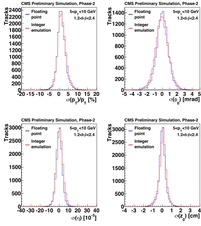
implemented on a FPGA. The floating-point simulation and the integer-based emulation are in good agreement. As an example, track parameter resolutions are compared between the floating-point
simulation and the integer-based emulation in Figure 6 for muons with 5 < pT < 10 GeV/c and
1.2 < |η| < 2.4. The root mean square (RMS) of each distribution is calculated. The resolutions as obtained with the integer-based emulation and the (exact) floating-point simulation are compared using (RMSinteger−RMSfloat)/RMSfloat, calculated to be 0.08, 0.10, 0.12, and 0.13 for the relativepT,
φ,η, andz0resolution, respectively, demonstrating a good level of agreement.
5 Hardware system
The primary challenges in building a L1 track trigger system are the large data throughput from the detector at 40 MHz and the short time available to reach a trigger decision. The upgraded L1 trigger will have an overall latency, i.e. the maximum time during which events can be stored in on-detector pipeline memories, of 12.5μs, where 4μs are allocated to performing the L1 track finding.
To address these challenges, the tracklet hardware configuration relies on parallel data processing. The detector is divided into sectors in ther-φ-plane. The current baseline uses 28φsectors, so that tracks withpT >2 GeV/cspan maximally two sectors. This limits the need for data transfer between sectors to the nearest neighbor on each side. A dedicated processing board is used for each sector.
To increase the time available for data processing, the system is time multiplexed. The current baseline assumes a time-multiplex factor of six, so that each copy of the system receives a new event every 150 ns for a 40 MHz bunch crossing frequency. A different time-multiplex factor of e.g. four or eight (receiving a new event every 100 or 200 ns) could also be considered in optimizing for latency or available processing time. The tracklet formation is performed within sectors and a small amount of data is duplicated in every other layer to avoid gaps. Tracklets that project to a neighboring sector are sent there for tracklet–stub matching. By construction, the system operates with a fixed latency.
5.1 Firmware implementation
The tracklet algorithm is implemented in firmware as eight processing steps and two transmission steps [4]:
• Stub organization:(1) Sort the input stubs by their corresponding layer, and (2) into smaller units inzandφ, forming what are referred to as "virtual modules".
• Tracklet formation: (3) Select possible tracklets from allowed stub pairs using lookup tables, and (4) calculate the initial tracklet parameters.
• Projections:(5) Transmission of projections pointing to neighboring sectors. (6) Route the projec-tions based on smaller units inzandφ.
• Stub matching: (7) Match projected tracklets to stubs, and (8) calculate the difference in position between the stubs and projected tracklet. (9) Transmission of matches between sectors.
• Track fit:(10) Perform track fit, correcting the initial tracklet parameter estimate.
[%]
T)/p
T(p
σ
-20 -15 -10 -5
0
5 10 15 20
Tracks
0
200
400
600
800
1000
1200
1400
1600
1800
2000
2200
2400
Floating point Integer emulation <10 GeV T 5<p |<2.4 η 1.2<| CMS Preliminary Simulation, Phase-2) [mrad]
0φ
(
σ
-5 -4 -3 -2 -1 0 1 2 3 4 5
Tracks
0
200
400
600
800
1000
1200
1400
Floating point Integer emulation <10 GeV T 5<p |<2.4 η 1.2<| CMS Preliminary Simulation, Phase-2]
-3) [10
η
(
σ
-40 -30 -20 -10 0 10 20 30 40
Tracks
0
500
1000
1500
2000
2500
3000
Floating point Integer emulation <10 GeV T 5<p |<2.4 η 1.2<| CMS Preliminary Simulation, Phase-2) [cm]
0(z
σ
-4 -3 -2 -1 0
1
2
3
4
Tracks
0
500
1000
1500
2000
2500
3000
Floating point Integer emulation <10 GeV T 5<p |<2.4 η 1.2<| CMS Preliminary Simulation, Phase-2Figure 6: Relative resolution in pT (top left), resolution inφ0 (top right), η(bottom left), and z0
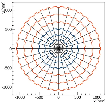
Figure 7: Schematic view in ther-φ-plane of the upgraded outer tracker, dividing into 28φsectors
so that a track with pT > 2 GeV/cspans maximally two sectors, limiting the communication
be-tween sectors. PS modules (blue) and 2S modules (red) are used in the three inner and outer layers, respectively.
The combinatorics in forming tracklets and matching projections to stubs is efficiently reduced by
dividing sectors into smaller units inzandφto allow additional parallel processing. These smaller
units are, as mentioned above, referred to as "virtual modules". Only a small fraction of virtual module pairs can form a valid tracklet – the majority would be inconsistent with a track withpT >2 GeV/c and|z0| < 15 cm. This subdivision efficiently reduces the number of combinations that need to be tried by the algorithm already before doing any event processing.
As the system operates at fixed latency, a given processing step can perform a fixed number of operations. Initial studies of the impact of truncation, such as if there are more stub pairs to try than can be processed within the time constraints of the tracklet formation step, show a robustness of the algorithm to these effects. This is achieved through the use of virtual modules, and the redundancy in using multiple seeding pairs.
The tracklet algorithm including the track fit has been implemented in firmware for half the barrel (z>0) for one sector inφ. Work is ongoing to expand the project to include the forward disks. The tracklet algorithm in the disks is already fully implemented as an integer-based emulation. While the duplicate removal algorithm has not yet been incorporated into the main tracklet project, it is fully implemented in the floating-point simulation, the integer-based emulation, and as a standalone
algorithm in firmware on a VC709 evaluation board with a Virtex-7 FPGA [5].
5.2 Hardware demonstrator
A system hardware demonstrator has been set up and is now being used for testing the tracklet project. The goal of the demonstrator is to show that the full tracking chain meets the required performance
slice. A total of four boards are used, one for the centralφsector, two for its nearest neighbors, and one board that is shared for sending the stub input and receiving the track output.
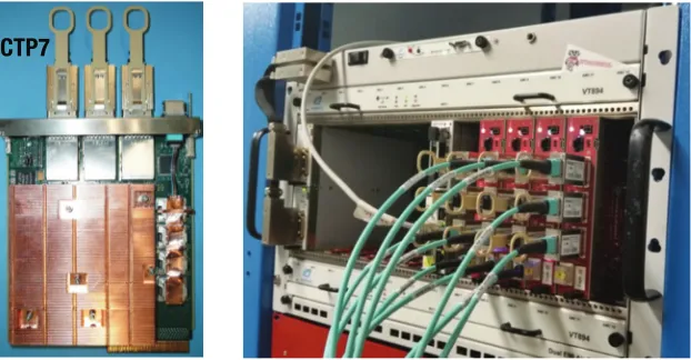
The boards used for the demonstrator system are μTCA boards with a Xilinx Virtex-7 (XC7VX690T) FPGA [5] and a Xilinx Zynq processor for outside communication. These so-called CTP7 boards [6] were developed for the current CMS L1 trigger upgrade [7]. An AMC13 [8] card provides the central clock distribution. The inter-board communication uses 8b/10b encoding with 10 Gbit/s link speed. The demonstrator system and a CTP7 board are shown in Figure8.
CTP7
Figure 8: A CTP7 board (left) and the tracklet demonstrator system (right).
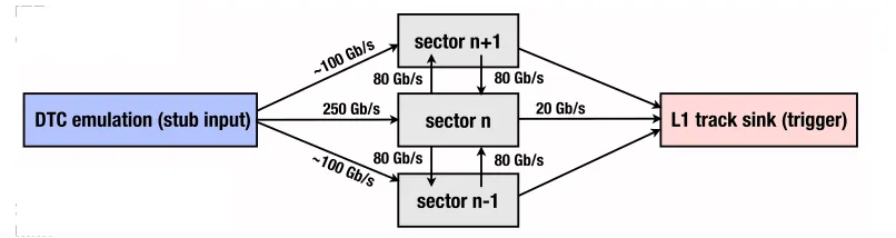
Oneφsector for a half-barrel has been implemented on the CTP7 boards, running at 240 MHz. Events are processed through the demonstrator as illustrated in Figure9. First, input stubs obtained from simulations are written to the data trigger and control (DTC) emulator board. On a GO signal, stubs are sent to the three sector processor boards. A new event is sent to each sector board every 150 ns. The events are processed through the sector boards and projections and matches are sent to and received from neighboring boards as required. The final output tracks are received by the track sink board. Systematic studies are performed to compare the integer-based emulation of the tracklet algorithm with a simulation of the firmware using Vivado, as well as with the output tracks from the demonstrator system. Full agreement is observed in processing single-track events between the emulation, firmware simulation, and board output. Studies of many-track events with high pileup are ongoing.
6 Conclusions
sector n sector n+1
sector n-1
DTC emulation (stub input) 250 Gb/s L1 track sink (trigger) ~100 Gb/s
~100 Gb/s
20 Gb/s 80 Gb/s
80 Gb/s 80 Gb/s
80 Gb/s
ing
ulation separately)
boards (one shared for tput)
Figure 9: Schematic overview of the tracklet demonstrator system. The DTC emulator and L1 track sink use a single board.
system based on Virtex-7 FPGAs has been assembled and is currently being used to validate the algorithm and board-to-board communication, to measure timing and latency, and to establish the algorithm performance. Preliminary studies from the demonstrator, processing events from the input stubs to the final output tracks, show promising results for the feasibility of the system within the available latency.
Acknowledgements
This work was supported by the US National Science Foundation through the grant NSF-PHY-1307256 . I also wish to thank my tracklet colleagues at Cornell, Rutgers, Ohio State, Notre Dame, and UC Riverside.
References
[1] F. Zimmermann, PoSEPS-HEP 2009, 140 (2009),https://cds.cern.ch/record/1211584
[2] The CMS Collaboration, JINST3, S08004 (2008)
[3] The CMS Collaboration, Tech. Rep. CERN-LHCC-2015-010, CERN, Geneva, Switzerland
(2015),https://cds.cern.ch/record/2020886
[4] J. Chaves, JINST9, C10038 (2014)
[5] Xilinx Incorporated,7 Series FPGAs Overview, last accessed on 2016-07-21,pdf
[6] A. Svetek et al., JINST11, C02011 (2016)
[7] The CMS Collaboration, Tech. Rep. CERN-LHCC-2013-011, CERN, Geneva, Switzerland
(2013),https://cds.cern.ch/record/1556311
![Figure 4: Efficiency for L1 track reconstruction as a function of η (left) and pT (right) for muons,pions, and electrons in events with <PU>=140 [3].](https://thumb-us.123doks.com/thumbv2/123dok_us/8153670.1359898/5.482.52.434.468.595/figure-eciency-track-reconstruction-function-right-electrons-events.webp)