International Journal of Research in Advent Technology, Vol.4, No.8, August 2016
E-ISSN: 2321-9637
Available online at www.ijrat.org
97
Control and Interfacing of BLDC Motor with
LABVIEW Using MYRIO
Rathy G. A
1Associate Professor, Electrical Department, NITTTR, Chennai, India.
Aravind Balaji
2P.G Student, Gojan Engineering College , Chennai, India.
Email: [email protected], [email protected]
Abstract-: Permanent Magnet Brushless DC Motor (PMBLDC) motors are gaining popularity in industries like automotive, aircrafts, medical Appliances, industrial drives and instrumentation because of their high efficiency, silent operation, high power factor, reliability, compact, low maintenance and high torque to power ratio. The PMBLDC motor requires an inverter and a position sensor that exposes rotor position for appropriate alternation of current. The rotation of the PMBLDC motor is built on the feedback of rotor position that is gained from the hall sensors. PMBLDC motor generally utilizes three hall sensors for deciding the commutation sequence. In the proposed work, the control in the inverter circuit can be achieved using MYRIO. The pulses can be generated from PWM pins of myRIO in a sequence and that can be used to control power devices of the inverter circuit. This paper aims at generating the PWM pulses in the required sequence and there by achieve the speed control of the BLDC motor with myRIO.
Index Terms- MYRIO, PWM, inverter circuit, Hall sensors, Multisim, Labview and cosimulation
1. INTRODUCTION
DC motors have a high starting torque and were preferred for adjustable speed applications. The DC motor has drawbacks such as Field losses and sparking in the brushes and so the construction of the DC motors were altered and this resulted in the Permanent Magnet Brushless DC motor. Brushless DC (BLDC) motors. The winding of BLDC motor is suitably connected to a DC supply through power Electronic circuitry. To rotate the BLDC motor, the stator windings should be energized in a sequence. It is important to know the rotor position in order to understand which winding will be energized following the energizing sequence. Rotor position is sensed using Hall Effect sensors embedded into the stator. When using Pulse Width Modulated (PWM) outputs to control the six switches of the three-phase bridge, variation of the motor voltage can be achieved easily by changing the duty cycle of the PWM signal. This paper aims at generating the PWM in a sequence using MYRIO and thereby achieves the speed control of the BLDC motor.
2. REVIEW OF LITERATURE
Oshin O Laxman(2016) in his paper on BLDC motor speed control using co-simulation of multisim and labview has theoretically suggested that as a future work a real time control operation for a brushless dc motor integrating LabVIEW tool such as my RIO or my DAQ can be developed[2]. A Ganesan et al (2015) has suggested in his paper Stepper Motor Control using LabVIEW and NI-myRIO, the pulse required to run the stepper motor is generated using NI myRIO
and interfaced with LabVIEW with the help of code generated in the system. In that paper the authors suggested that the supply voltage is given to the motor through a voltage driver circuit and the motor’s speed is controlled by varying the time delay in the LabVIEW program simulation specifications[6].
3. BLDC MOTOR CONTROL
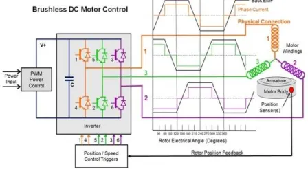
BLDC motor driver system contains BLDC motor, 3 phase inverter and a digital controller unit.
Fig. 1. Existing BLDC Motor Control circuit
98 position can be determined by a Hall effect devices,
embedded in the stator, which provide an electrical signal representing the magnetic field strength. The amplitude of this signal changes as the magnetic rotor poles pass over the sensor. By simply varying the voltage across the motor, one can control the speed of the motor. The PWM techniques are used to switch ON or OFF the switches. In order to vary the speed, these signals should be Pulse Width Modulated (PWM) at a much higher frequency than the motor frequency. The PWM frequency should be at least ten times that of the maximum frequency of the motor [5]. When the duty cycle of PWM is differed within the sequences, the average voltage supplied to the stator is reduced, thus lowering the speed. When using PWM outputs to control the six switches of the three-phase bridge, variation of the motor voltage can be achieved easily by changing the duty cycle of the PWM signal.
Fig. 2. Controlling of six switches in the three-phase bridge of the inverter circuit
4. MULTISIM
Multisim is a teaching environment that combines intuitive schematic capture and simulation functionality. In this paper the 3 phase inverter circuit is generated in Multisim and the simulation is done. With system-level simulation, it is possible to implement point-by-point simulation between two separate simulation engines: analog SPICE circuitry and digital logic. This functionality is exclusive to the Multisim and LabVIEW platform through an approach called cosimulation. Cosimulation allows a unique time-step negotiation between two simulation engines to create a closed-loop simulation of the complete system. The result is an evaluation of a design that includes all of the system dynamics between the analog and digital modules. Multisim, which is optimized for accurate analog and mixed-signal circuitry, includes a large set of predefined SPICE models from leading semiconductor manufacturers such as Analog Devices, NXP, ON Semiconductor, and Texas Instruments. The LabVIEW simulation engine is dedicated to the effective design and implementation of control logic through a graphical,
dataflow representation. This engine provides high-level simulation optimized for embedded digital code for Electrical systems.
a. Cosimulation
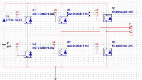
To perform Co-Simulation, the Control Design and Simulation module tool along with LabVIEW 2014, multisim with LabView cosimulaton plugin is required. The analog inverter circuit is draw using multisim. After placing the components, double click each one to change the values as required.
It is now required to place the terminals that send and receive data to and from the LabVIEW simulation engine. These terminals in Multisim are Hierarchical Block or Sub-Circuit (HB/SC) terminals. Right-click and select Place on schematic»HB/SC connector from the shortcut menu or simply type <Ctrl-I>. Place one HB/SC connector above and to the left of the schematic and another connector above and to the right of the schematic.
To configure HB/SC connector as an input or output in LabVIEW,the LabVIEW Co-simulation Terminals window is selected by Navigating to View»LabVIEW Co-simulation Terminals.Then configure each connector as a voltage or current input/output by selecting the Type. Configure s1 to s6 as an Input and A, B, C as Outputs.
In Multisim design VI preview updates with the selections that is made. This is a preview of the virtual instrument (VI) that is used to later place in LabVIEW to interface with this Multisim circuit. If it is required to change the input and output terminal names of this Multisim VI, modify the text of the LabVIEW Terminal setting. The commutation algorithm generated in Labview and driver circuits prepared in Multisim are integrated by the co-simulation feature of Labview and Multisim programs.
99 Fig. 3b. Switching sequence
Fig. 3a. Shows the control circuit of BLDC motor in which switching is done using six IGBT with freewheeling diode for reverse current protection. Fig 3b shows the six switching patterns depending upon the hall sensor output for rotor movement.
5. LABVIEW CODE FOR INVERTER CIRCUIT
LabVIEW based programming environment is very much suitable for computer based measurement and data acquisition. LabVIEW is a highly productive, development environment for creating custom application that interact with the real world signals in fields engineering.
Fig. 4. Rotor position switching sequence
Fig. 4. shows hall sensors sensing the position and turning on the required switches[3]. PWM are generated in such a way that two switches are turned on at the same time which closes the current flow in the circuit.
While working with co-simulation toolbox, inverter designed in multisim and the three hall sensor output from the motor is made to communicate with the labview. The control circuit is designed in labview and the output data from the multisim is the input to the labview. These are then processed and the switching pulse is generated which is then send to the inverter circuit designed in multisim.
While working with co-simulation toolbox, inverter designed in multisim and the three hall sensor output from the motor is made to communicate with the labview. The control circuit is designed in labview and the output data from the multisim is the input to the labview. These are then processed and the switching pulse is generated which is then send to the inverter circuit designed in multisim..
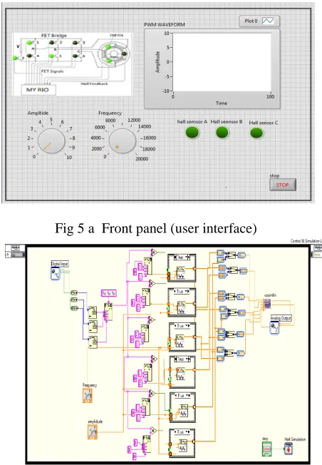
As shown in fig 5 a the speed of the dc motor is adjusted by varying the pwm duty cycle using virtual knob which controls the average dc bus voltage. The amplitude of PWM generated can be varied by the amplitude knob. The PWM waveform can be plotted in a waveform chart. The rotor position can be found out by the indication of the LEDs.
Fig 5 a Front panel (user interface)
Fig 5 b Block diagram (coding)
Fig 5 b . The three hall sensor output from the motor is acquired on to LabVIEW using MY-RIO and are concatenated as string inputs so that the rotor position sequence is generated. This sequence is then compared with the six constant sequences(as in Fig 3 b) such that PWMs are generated to switch the particular switches, to move the motor to the next position. This PWM switching input is given to the input of IGBTs in cosimulation block and depending upon which output sequence is generated at the output of myRIO which is connected to the BLDC motor along with a external power source.
6. NI-myRIO
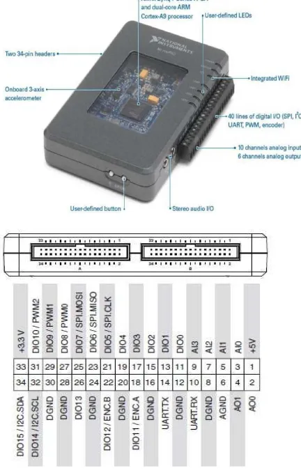
100 consists of two expansion port (MXP) connectors A
and B carry identical set of signals and both have 34 pin outs and a mini system port (MSP) called Connector C. In both the cases there are certain pins which carry primary and secondary functions. Signals can be acquired and processed in LabVIEW and the generated signals can be used in real time. NI-myRIO has 3.3v, 5v, +/- 15v power output. It provides connectivity with the host computer either over USB or wireless connectivity. It has an inbuilt accelerometer and special functions like Pulse width modulation, UART, Audio input and output terminals[1][3].
Fig 6 myRIO and its pin details
The figure 6 shows the pin out diagram of mini system port from which we have generated digital signals to trigger BLDC motor[7][8].
The circuit is configured in such a manner that the RIO powers the driver circuit. My-RIO can only give an output maximum of 10 V, 300 Ma which is not sufficient to drive a 24 V BLDC motor and hence an external power source is provided to drive the motor
7. INTERGRATING myRIO and LabVIEW
Fig 7 Dataflow diagram between multisim and LabVIEW
8. HARDWARE SETUP
The hardware set up is shown in figure 8 below. The power supply to run the BLDC motor is 24 volts.The output of myRIO is only 10 V. Hence External power suply was used to run the 24 V BLDC motor. An encoder motor is provided inorder to note the RPM of the motor and are in displayed in a 7segement display.
Fig 8 Hardware setup myRIO Controlling BLDC motor
9. OUTPUT- RESULT
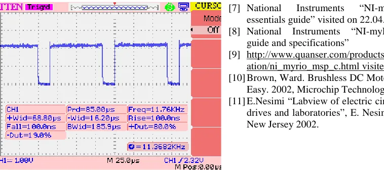
The PWM wavefoms generated from the PWM blocks of the myRIO at 40% and 80% duty cycle are been noted using CRO and by varying the frequency knob the duty cycle is varied which is shown in figure 9.
101 Fig 9 b PWM1 80% duty cycle
Fig 9 a and b shows the output at 40% and 80% of the duty cycle.
10. CONCLUSION
The control circuit is drawn in multisim and using the design and co-simulation it is interfaced with labVIEW. The PWM block in the LabVIEW code is then used to generate the pulses and depending on the position of the hall sensors the pulses are given to the six IGBT switches in the Control circuit by acquiring the analog output through myRIO.
REFERENCES
[1] http://www.ni.com/white-paper/13721/en/myrio visited on 22.04.2016
[2] Oshin O Laxman , Girisha Joshi, 2016, BLDC motor speed control using co-simulation of multisim and labview, International Journal of Innovative Research in Electrical, Electronics, Instrumentation and Control Engineering Nitte Conference on Advances in Electrical Engineering NCAEE-2016 NMAM Institute of Technology, Nitte Vol. 4, Special Issue 2, April 2016, ISSN (Online) 2321 – 2004 ISSN (Print) 2321 – 5526
[3] http://www.ni.com/NI-Tutorial-4752-en.pdf. [4] R. Somanatham , P. V. N. Prasad , A. D.
Rajkumar, 2006, Simulation of PMBLDC Motor With Sinusoidal Excitation Using Trapezoidal Control Strategy, (ICIEA 2006) 0-7803-9514-X/06
[5] S. Prakash , R. Dhanasekaran , Syed Ammal, 2011, 'Modelling and Simulation of Closed Loop Controlled Buck Converter Fed PMBLDC Drive System', Research Journal of Applied Sciences, Engineering and Technology 3(4): 284-289, ISSN: 2040-7467
[6] A Ganesan et al.(2015), Stepper Motor Control using LabVIEW and NI-myRIO IJSRD - International Journal for Scientific Research & Development| Vol. 2, Issue 12, 2015 | ISSN (online): 2321-0613
[7] National Instruments “NI-myRIO project essentials guide” visited on 22.04.2016.
[8] National Instruments “NI-myRIO-1900 user guide and specifications”
[9] http://www.quanser.com/products/rcptk/document ation/ni_myrio_msp_c.html visited on 22.04.2016 [10]Brown, Ward. Brushless DC Motor Control Made
Easy. 2002, Microchip Technology Inc.