20
Performance Analysis of Shut Reactor Switching with
Controlled Switching method
Mr. Durgadas Ashok Chitare1, Prof. A.V.Harkut2
Department of Electrical (Electronics & Power) Engineering1,2 Students of Electrical Engineering1 Faculty of Electrical Engineering2
Email:[email protected]1,[email protected]2
1. INTRODUCTION
The major compensation device use in the power system is a reactor and shut reactor are most use in substation for voltage compaction. Shunt rector have two application in substation one is bus reactor and second is line rectors. This shunt reactor have frequent switching but due to shunt reactor switching cause some effect on power system. Like switching surges due to inrush current, dc offset current, restrike on opening. Due to this all problems we reduce the controlled switching method introduce in 1990s.
Controlled switching method eliminate all issue vie time controlled switching operation of Circuit breaker. Now a days all the substations in India we use the controlled switching devices. In this method precise angle are selected for both the open and close operations. If we give open command to the circuit breaker at exact current zero position and close command at voltage pick position then we automatically eliminate all issue and provide reliable
power to the customer with better power quality. In this paper I Annalise the aspect of shut reactor switching and associate problem with controlled switching devices
1. SHUNT REACTOR SWITCHING
For analysis of shunt reactor switching I used 125MVAR shut reactor both the bus reactor and line reactor used and collect all the result of 125 MVAr reactor of 400kv substation. The function of shunt reactor in transmission network is to consume the excess reactive power generated by overhead line under low load condition, and thereby stabilize the system voltage. They are often switch as per load condition. Energizing of shunt reactor may cause the inrush current with high asymmetry called DC offset. The magnitude of inrush current depend upon the reactor core and time instant of circuit breaker close with respect to reference signal. As we use the shut reactor for bus reactor application then shunt reactor is solidly grounded neutral in this case unsymmetrical current occur. Shunt reactor details specifications are mention in table no 1.
Table 1. Shunt reactor 125 MVAr data
Abstract-This paper describe the performance analysis of shunt reactor with uncontrolled and controlled switching method. Shunt reactor widely developed by power utility to regulate the reactive power balance and to control voltage level on power line. They are commonly used in transmission substation and SVC (static Var Compensator) installation. An uncontrolled or random switching of shunt reactor causes disturbance and asymmetrical current which after time, damages HV circuit breakers and equipment failures and eventually blackout. Different Controlled switching method addresses every one of these issue by operating circuit breaker at optimal moment so as to prevent disturbance and asymmetrical current when switching shunt reactor. So I used newly developed controlled switching method for analysis and all analysis done on the load of 125 MVAr 400kV shunt reactor. In this paper I study some practical graphs of shunt reactor switching which I practically commissioned on 400kV substation in India. The analysis contain asymmetrical current or DC offset behavior and how practically this asymmetrical current arises in the system when shunt reactor switching. The inrush current practical graphs and cause of this inrush current, risk of restrike on opening, voltages and current reference angle selection for controlled switching shunt reactor when the of shunt reactor use in both bus reactor and line reactor application
21 Rated power 125 MVAr
Rated frequency 50 Hz Rated voltage 420 kV No of phase 3 phase Rated Current 172 A System fault level 40 kA Connection Star Type of construction Gapped core
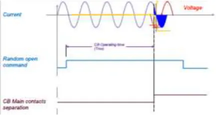
2.1 Random opening of shunt reactor
When random opening of the shunt reactor there is no any synchronization delay in command. The command is direct sent to the circuit breaker at that instant any angel of current reference due to which restrike and voltage imbalance occur.
.
Fig 1. The sequence of random Opening
2.1.1. Restrike or resignation
At opening of shunt reactor the most observe dangerous phenomena is restrike or resignation. When the dielectric withstand is less than the voltage across the breaker contact flashover occur and current start to flow again this is called restrike.
Fig 2. Restrike or resignation
This restrike cause by the two factor first one angle at a time of switching and second is dielectric withstand.
Due to this restrike current continue start flow for next half cycle then the power require to extinguish this arc is more than the normal arc at this condition more power loss occur and more heat generate. In air insulated circuit breaker when produce more heat chances will be more for breakdown.
2.2 Controlled opening shunt reactor
In this controlled action some synchronization delay add in the command to find out the exact opening point with respect to reference current. Reference current taken from the CT secondary connected to same breaker bay. There are two method for reference selection either we take a current or take voltage reference from CVT. Shunt reactor is an inductive load and therefore current and voltage consider to be 90 degree apart from each other. But for precise result we must take current as reference. Load current have 50Hz frequency. As shown in fig 3 controlled switching device detect the current zero of ref. current then add some synchronous delay for calculating the exact time require to send command to the CB. When command send from the control switch of CB this command hold in controlled switching device then send to the CB. Suppose actual time for opening of CB is 20ms then device take as reference time now we consider as actual time (Ta), time require for current zero detection is a synchronization time (Ts), time require from controlled room to CB command initiation travel time (Tt). Total time require to controlled open command (To).
To= Ta + Ts+ Tr + Tt
Fig 3. The sequence of controlled opening
2.2.1 Shunt reactor opening angle
22 Before we select the angle of switching for reactor we
must know the configuration of shunt reactor. There are three main configuration of shunt reactor this configuration depend upon the earthing system use for the same. Also when the earthing system change application rector also change. For the line reactor application neutral grounding resistance used and for bus reactor application solid ground use this two different earthing configuration used in power substations.
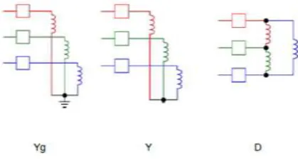
Fig 4. Reactor configuration
This above three configuration give details about the connection of three phases of reactor. If three phases are star connected and earthed then this configuration called Yg. If all phases are star but not earthed then called Y. If three phases connected in delta called D. I used only the Yg configured reactor. So for opening current as reference and 0, 120, 60 are the angle for voltage ref 90,210,150 are the angle of selection. When I configure the relay with 0,120,60 of current reference the following result are found for 125MVAr, 400kV shunt reactor there is no restrike and no voltage imbalance at the time of opening.
Fig.5 R phase opening graph
Fig. 6 Y phase opening graph
Fig. 7 B Phase opening graph
2.3 Random closing of shunt reactor
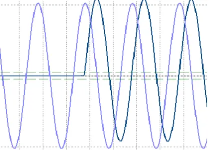
23 Fig. 8 Asymmetrical closing current
When I was do the closing at random closing operation R phase had this asymmetrical closing current.
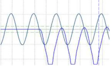
Fig. 9 Inrush current during Closing B phase
When doing the closing operation B phase had this inrush current. This inrush current had 2.3 per unit value. This a huge current at charging of shunt reactor due to this voltage imbalance.
2.3.1 Controlled closing of shunt reactor
When I do precise angle setup for controlled closing the both asymmetrical current and inrush current eliminated from the graphs this give the accurate closing of shunt reactor. For closing I select the closing angle as 90,210,150 of voltage because at closing we don’t have any current references. So as we consider shunt reactor as inductive load if we select the voltage peak we automatically got the current zero instant.
Fig.10 Symmetrical closing current
Fig. 11 R Phase closing graph
24 Fig. 13 B Phase closing graph
Fig. 11,12,13 show the results of controlled closing of shunt reactor and observe that all the closing current initiation with the voltage picks of respective of each voltage sequence
3. CONCLUSION
This paper describe the performance analysis of the uncontrolled and controlled switching of shunt reactor. In uncontrolled open operation restrike or reigniting observed but in controlled operation all the phases restrike eliminate.
In closing operation asymmetrical or DC offset current observed in uncontrolled closing operation of reactor also inrush current observed this two factor eliminated in controlled closing operation.
As a consequence controlled switching operation reduce the mechanical and electromechanical stress on shunt rector also prevent unwanted operation of protection. Also reduce instability in power system and improve power quality.
REFERENCES
[1] CIGRAE report ELEKTRA, no 163.
[2] “SWITCHSYNCE 113 for synchronous switching of circuit breaker”, ABB product information, vol.5409pp.722-96E
[3] IEC 62271-100: High-voltage switchgear and controlgear; High-voltage alternating-current circuit-breakers, 2003.
[4] CIGRE TF13.00.1, “Controlled Switching, State-of-the-Art Survey”, Part 1: ELECTRA, No.162, pp. 65-96, Part 2: ELECTRANo.164, pp.
39–61, 1995
[5] Ali F. Imece, D. W. Durbak, H. Elahi, S. Kolluri, A. Lux, D. Mader, T. E. McDemott, A. Morched, A. M. Mousa, R. Natarajan, L.Rugeles, and E. Tarasiewicz, "Modeling guidelines for fast front transients", Report prepared by the Fast Front Transients Task Force of the IEEE Modeling and Analysis of System Transients Working Group, IEEE Transactions on Power Delivery, Vol. 11, No. 1, January 1996.
[6] Z. Gajić, B. Hillstrom, F. Mekić, “HV shunt reactor secrets for protection engineers”, 30thWestern Protective Relaying Conference,Washington, 2003 [7] IEEE Guide for the Application of Shunt Reactor Switching,"IEEE Std C37.015-2009 (Revision of IEEE Std C37.015-1993), vol., no., pp.c1,53, Feb. 12 2010.
[8] Modelling of Restriking and Reignition Phenomena in Three-phase Capacitor and Shunt Reactor Switching by Shui-cheong Kam School of Engineering Systems Queensland University of Technology ,Brisbane, Australia.
.