7170
Device
Attachment
Control
Unit
Reference
and Operations
Manual
Federal Communications Commission (FCC) Statement
Warning: This equipment generates, uses, and can radiate radio frequency energy and if not installed and used in accordance with the instruction manuai, may cause interference to radio communications. It has been tested and found to comply with the limits for a Class A computing device pursuant to Subpart J of Part 15 of FCC Rules, which are designed to provide reasonable protection against such interference when operated in a commercial environment. Operation of this equipment in a residential area is likely to cause interference in which case the user at his own expense
will be required to take whatever measures may be required to correct the
interference.
Third Edition (October 1984)
This edition applies to Release 1.1 of the Device Attachment Control Unit (DACU), and to all subsequent releases of this product until otherwise indicated in new editions or Technical Newsletters.
References in this publication to mM products, programs, or services do not imply that mM intends to make these available in all countries in which mM operates. Any reference to an IBM program product in this publication is not intended to state or imply that only mM's program product maybe used. Any functionally equivalent program may be used instead.
Ordering Publications
Preface
The purpose of this manual is to provide comprehensive documentation for the Device Attachment Control Unit. It covers:
1. Introductory information, including a general description of the hardware and the function of its major logical elements.
2. Programming considerations and examples for both host and local programming.
3. Procedures for installing and operating a DACU as well as procedures for diagnosis and problem resolution.
4. General and physical characteristics and performance considerations. 5. Appendices include sample host programming and reference material.
How this Book is Organized
Among the major divisions of this publication are:
• Installation Planning "Chapter 7. Physical Characteristics and Installation Planning Information" on page 137 describes the physical characteristics of the DACU and installation preparation considerations.
• Customer Set-up and Operating Instructions see "Chapter 5. Installing and Operating the DACU" on page 91.
• Maintenance Recommended techniques for problem analysis and problem resolution are given in "Chapter 6. Customer Problem Analysis and Resolution" on page 105.
• Host Programming Techniques and examples are given in "Chapter 3.
Programming Considerations" on page 13 as well as in the host programming appendix.
About This Manual
This manual is a major re-write of the 7170 Device Attachment Control Unit
Reference and Operation Manual DACU-ROM-O. It is released in conjunction with a hardware change which brings the DACU to level I. I. The major changes are: • Inclusion of customer problem determination procedures
• New control space op codes
• Complete listings of host application language libraries HALLS and HALLGE • Explanation of DACU information and warning messages
Contents
Chapter 1. General Product Description . . . • . . . • . . • . 1
Conceptual Data Flow ... 2
Parallel I/O Interface Operations ... 2
Serial I/O Operations ... 3
Configurations ... 3
Architectural Considerations ... 3
External User Interface ... 3
Compatibility with Programming Support ... 4
Customer and Service Information Highlights ... 4
Chapter 2. Hardware Description ...•...•....•....•...••... S Basic Data Flow ... 6
Data Flow Unit Descriptions ... 7
DACU System Unit ... 7
DACU Interface Unit ... 8
DMA Control ... 10
OEMI Adapter ... 10
Parallel I/O Interface Adapter ... 10
Serial I/O Adapter ... 11
Byte Coordination ... 11
Chapter 3. Programming Considerations ...•...•....•....•...•... 13
Generic Logical Device Commands ... 13
Device 0: Control Unit ... 16
Device 4: Parallel I/O Interface Adapter ... 20
Device 1 and 2: Serial I/O Ports One and Two ... 26
Host Programming Support ... . . . .. 31
I/O Programming Support ... 31
Sample Host Programming Techniques ... 33
Host Programming Considerations for Devices ... 38
Programming for Parallel I/O Devices ... 38
Programming for Serial I/O Devices ... 49
Chapter 4. Local DACU Programming ...•...•...•....•. S9 DACU Control Program Characteristics ... 59
Customer Local Programming Structure ... 60
Control Space Areas ... 62
Utility Macro Libraries ... 62
General Utility Macro Library ... .. . . . .. 62
Parallel I/O Utility Macro Library ... 67
Serial I/O Utility Library ... 69
Sample Assembler Programs ... . . . .. 71
General Utility Subroutine Library 0 0 0 0 0 0 0 0 0 0 0 0 0 0 0 0 0 0 0 0 0 0 0 0 0 0 0 0 0 0 0 0 74
Parallel I/O Subroutine Library 0 0 0 0 0 0 0 0 0 0 0 0 0 0 0 0 0 0 0 0 0 0 0 0 0 0 0 0 0 0 0 0 0 0 79
Serial I/O Subroutine Library 0 0 0 0 0 0 0 0 0 0 0 0 0 0 0 0 0 0 0 0 0 0 0 0 0 0 0 0 0 0 0 0 0 0 0 84
Sample FORTRAN Programs 0 0 0 0 0 0 0 0 0 0 0 0 0 0 0 0 0 0 0 0 0 0 0 0 0 0 0 0 0 0 0 0 0 0 0 86
Sample PASCAL Programs 0 0 0 0 0 0 0 0 0 0 0 0 0 0 0 0 0 0 0 0 0 0 0 0 0 0 0 0 0 0 0 0 0 0 0 0 0 88
Chapter S. Installing and Operating the DACU •.•.•..•.•••••••••••••.•.• 91 Installation-Inside the System Unit 0 0 0 0 0 0 0 0 0 0 0 0 0 0 0 0 0 0 0 0 0 0 0 0 0 0 0 0 0 0 0 0 0 91
Installation-Interface Unit 0 0 0 0 0 0 0 0 0 0 0 0 0 0 0 0 0 0 0 0 0 0 0 0 0 0 0 0 0 0 0 0 0 0 0 0 0 0 0 92
System Unit Power 0 0 0 0 0 0 0 0 0 0 0 0 0 0 0 0 0 0 0 0 0 0 0 0 0 0 0 0 0 0 0 0 0 0 0 0 0 0 0 0 0 0 0 0 92
DACU Memory Refresh Control Jumper 0 0 0 0 0 0 0 0 0 0 0 0 0 0 0 0 0 0 0 0 0 0 0 0 0 0 0 92
DACU Channel Address Set-Up 0 0 0 0 0 0 0 0 0 0 0 0 0 0 0 0 0 0 0 0 0 0 0 0 0 0 0 0 0 0 0 0 0 93
Cabling and DACU Interface Unit Power 0 0 0 0 0 0 0 0 0 0 0 0 0 0 0 0 0 0 0 0 0 0 0 0 0 0 94
DACU'Operator Switches and Indicators 0 0 0 0 0 0 0 0 0 0 0 0 0 0 0 0 0 0 0 0 0 0 0 0 0 0 0 0 0 95
Installing Parallel I/O Peripheral Adapters 0 0 0 0 0 0 0 0 0 0 0 0 0 0 0 0 0 0 0 • 0 0 0 0 0 0 0 0 96
"Back Panel" for Peripheral Adapters 0 0 0 0 0 0 0 0 0 0 0 0 0 0 0 0 0 0 0 0 0 0 0 0 0 0 0 0 0 96
Bus Grant Continuity 0 0 0 0 0 0 0 0 0 0 0 0 0 0 0 0 0 0 0 0 0 0 0 0 0 0 0 0 0 0 0 0 0 0 0 0 0 0 0 0 0 0 97
Non-Processor Grant 0 0 0 0 0 0 0 0 0 0 0 0 0 0 0 0 0 0 0 0 0 0 0 0 0 0 0 0 0 0 0 0 0 0 • • 0 0 • • • 0 97
Installation of Parallel I/O Peripheral Adapters 0 • • • • 0 • • • • • • • • • • 0 • 0 • • • 98
Wiring Arrangements for Serial Device Cables o. 0 0 0 0 • 0 • 0 • 0 • • 0 • 0 • • • • • • • • 98
Null Modem Cable 0 0 0 0 0 0 0 0 0 . 0 0 0 0 0 . 0 0 . 0 0 0 . 0 0 . 0 • 0 • • 0 . 0 . 0 • • • • 0 • • • 99
Flip Cable 0 0 0 0 0 0 0 0 0 • 0 0 0 0 0 0 0 • 0 • • 0 0 0 0 0 0 0 0 0 • 0 • 0 • 0 0 • • • • • 0 • 0 • • 0 • • 100
Installation of Control Programming 0 0 0 0 0 0 • 0 • • • 0 0 0 0 • 0 • 0 0 • 0 • 0 • • • • • • 0 100
The Supplied DACU Diskette 0 0 0 0 0 0 . 0 0 0 0 0 0 0 0 0 0 . 0 • • 0 0 0 • • • • • 0 • • • • 0 • • 100
DACU Initialization 0 0 0 0 0 0 0 0 • 0 0 0 • 0 0 0 0 0 0 0 0 0 0 0 • • • 0 0 • 0 0 • • • • : • 0 0 0 0 • • 101
DACU Keyboard Controls 0 0 0 . 0 0 0 0 0 0 0 0 • • 0 0 • • • • • 0 0 • • 0 • • • • • • 0 • • • • 102
Chapter 6. Customer Problem Analysis and Resolution ..•••••.••••••••••• 105 DACU Messages and Error Logging . 0 0 0 • • • • • • • 0 0 • • 0 • • • • • 0 . . . 105
Problem Determination Procedures ... 0 • 0 • • 0 • 0 0 • 0 • • • • • • • • 0 • 0 • • • • • • • 107
Customer Replaceable Units . 0 . 0 • • • 0 0 0 0 0 0 . 0 . 0 0 0 . 0 0 . • • • • • • • • • • • • 107
Diagnostics 0 0 0 0 0 0 • 0 • 0 0 • 0 0 0 0 0 0 0 0 0 • 0 0 0 • 0 0 • 0 • • • 0 0 • • 0 • 0 • • • • 0 • • • • 108
Service Information o . 0 0 • • 0 0 • 0 0 0 • 0 0 • 0 • • 0 0 0 0 • • 0 0 0 • • 0 • 0 • • • • 0 • • • • 108
Special Tools 0 0 0 0 0 0 • • • • 0 0 0 • 0 0 0 0 0 0 0 0 • • 0 • 0 0 • 0 • 0 • • 0 0 • • • • 0 • 0 • • • • 109
PDP Entry Point ... 0 • 0 0 0 0 • • 0 0 0 0 0 • • 0 0 • 0 • • • • 0 • 0 • • • • • • • • 0 • 0 • • • • • • 0 109
Mechanical Section o . 0 • • 0 0 0 0 0 0 0 0 0 0 0 0 0 • • • 0 • 0 • 0 • 0 • • • 0 • • • • 0 • 0 0 0 • 0 110
Power Section 0 0 0 0 0 0 ' 0 • 0 0 0 • 0 0 0 • 0 0 0 0 0 • 0 0 0 • 0 0 0 • 0 • • • • • • 0 0 0 • • • • 0 o . 113 Device Related Problem .. 0 0 0 • 0 0 0 0 0 0 0 0 • • 0 0 0 0 • 0 • 0 • • • 0 • • 0 • • • 0 0 0 " 116
Diagnostic Procedures 0 0 0 • • • 0 • 0 • 0 • • 0 0 0 0 0 • • 0 • 0 • • 0 • 0 • • • 0 • • 0 • • • • • 0 o. 117
Unit Replacement 0 0 0 0 • 0 • • • 0 0 • • • • • 0 0 0 0 0 0 • 0 • 0 0 0 • 0 • • 0 • • • 0 • • • • • • • • • 130
Field Replaceable Unit o. 0 • 0 • 0 • 0 0 • • • 0 0 0 • 0 • • • 0 • 0 • 0 • • • • 0 • • • • • 0 • • 0 130
Spare Parts 0 0 0 0 0 0 0 • 0 • • • • • • 0 • 0 • • 0 0 0 • 0 0 0 • • • 0 • 0 • 0 0 • • • 0 • • • • • • • • • 130
Replacement of DACU Unique Components in DACU System Unit .. 0 • • 131
Replacement of DACU Components in Interface Unit 0 " 0 • • • • 0 • 0 • • • • 132
Chapter 7. Physical Characteristics and Installation Planning Information ••••• 137 Physical Spe<.!ifications . 0 • • 0 • • • 0 • • • 0 • 0 0 • 0 • • • • • • • • • 0 0 • • • • • 0 • • • • • • • 137
Dimensions 0 0 0 0 0 • 0 • • • • • 0 0 0 0 • • 0 0 • 0 0 . 0 . 0 • 0 • 0 • 0 • 0 • • • • 0 • • • • • • • • • 137
Packaging . . . 140
System Unit Extender Card . . . 140
Power Adapter Card . . . 141
Interface Unit Adapter Card . . . 141
DMA/Memory Card . . . 141
OEMI Adapter Card . . . 142
Adapter for Parallel I/O Interface . . . 142
Chapter 8. Performance Characteristics ••.••••••.•••.••••••••••••.••• 143 Data Transfer Rates . . . 143
Programming for Maximum Performance . . . 144
Concurrency Considerations . . . 145
Appendix A. Sample Host Programming •••••••••••••••••••••••••••••• 147 Host Application Language Library using Start I/O ... 147
Introductory Information . . . 147
User Callable Subroutine Explanation . . . 147
Internal Subroutine Explanation . . . 151
Parallel I/O Application Programming Example ... 152
Serial I/O Application Programming Example ... 156
Source Code ... 158
Host Application Language Library using GAM and EXCP ... 170
Introductory Information . . . 170
User Callable Subroutine Explanation . . . 171
Internal Subroutine Explanation . . . 174
Parallel I/O Application Programming Example ... 174
Serial I/O Application Programming Example . . . 178
Source Code . . . 180
Appendix B. Serial I/O Translation Tables •••••••••••••••••••••••••••• 191 Appendix C. DACU Function. Code Messages ••••.•••...•••.••••.•••.• 195
Figures
1. Conceptual DACU Data Flow ... 2
2. Basic DACU Data Flow ... 6
3. DACU Memory Map. ... 9
4. Control Unit Logical Device Status Byte ... 19
5. Control Unit Logical Device Sense Bytes ... 20
6. Parallel I/O Interface Logical Device Status Byte ... 23
7. Parallel I/O Interface Logical Device Sense Bytes ... 24
8. Serial I/O Logical Device Status Byte ... 29
9. Serial I/O Logical Device Sense Bytes. . . .. 30
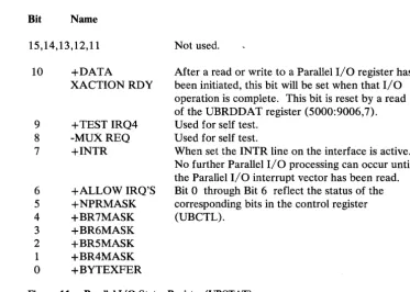
10. Parallel I/O Control Register (UBCTL) ... 40
11. Parallel I/O Status Register (UBST A T) ... 41
12. Refresh Control Jumper Block. . . .. 92
13. Address Range and Address Selection Jumper Blocks ... 93
14. Address Selection Example ... 93
15. DD-11 Block ... 96
16. Power Assembly Connectors ... 113
17. D.C. Power Connector J1 ... 114
18. D.C. Power Connector J2 ... 115
19. Card Replacement Priority Matrix ... 116
20. Problem Determination Flow Charts ... 126
21. Card Cable Plug Matrix ... 134
22. Card Plug Locations ... 134
23. Line Voltage Specification ... 138
24. Plan View/Clearance Drawing ... 139
25. Data Transfer Rates ... 143
Chapter 1. General Product Description
The Device Attachment Control Unit (DACU) is a control unit, adhering to the architecture of the IBM Original Equipment Manufacturers' Interface (OEMI) on an IBM 43XX or 308X Block Multiplexer Channel. The DACU is available in a single configuration (no optional features) which provides interfaces compatible with the UNIBUSl parallel, direct memory access interface and the EIA RS-232-C serial interface for the attachment of non~IBM, I/O devices. Control programs provided with the DACU are executed locally by the DACU System Unit (IBM Personal Computer) to support the requirements for I/O associated with attached devices, managing buffering and interrupts in a manner designed to provide flexibility and high overall throughput. Customer provided application- or
device-dependent program components may be written and executed locally in the DACU System Unit using supplied macro or subroutine facilities for customer written code.
Throughout this manual the interface which is compatible with the UNIBUS parallel, direct memory access interface will be referred to as the "Parallel I/O" interface. This interface is intended for the attachment of high performance I/O devices. It provides for emulated direct memory access I/O transfers to and from host system main storage. Such transfers are buffered in the DACU Interface Unit storage. Facilities for "programmed I/O" are provided as well. The Parallel I/O interface and associated DACU processing handle device interrupts in a manner that simulates I/O handling typical· of the environment for which these devices were designed.
EIA RS-232-C is a commonly used interface for attaching serially communicating devices. The DACU includes two such interfaces, providing half and full duplex asynchronous communication.
Throughout this manual, the RS-232-C-compatible, serial interface will be referred to as the "Serial I/O" interface.
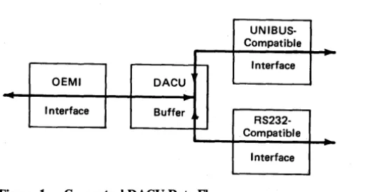
Conceptual Data Flow
The figure below illustrates the conceptual flow of data in the DACU Interface Unit.
UNIBUS-Compatible
Interface
OEMI DACU
Interface Buffer
RS232-Compatible
[image:13.620.180.445.147.284.2]Interface
Figure 1. Conceptual DACU Data Flow
Referring to the illustration, there are a number of useful conceptual data flow paths associated with attached UNIBUS-compatible devices:
• With a device Master, a DMA read/write path from/to DACU buffer address space
• Under DACU control, a programmed read/write path from/to the address space of a device
• A Channel read/write path from/to DACU buffer address space • A path for communicating interrupts from a device to the DACU. Similar paths exist for managing RS-232-C devices.
Parallel
110
Interface OperationsFrom an application's point of view, the Parallel I/O interface permits access to a "memory" address space with blocks of 64K bytes. Low memory is reserved for buffer memory, and the top 8K bytes of memory is reserved by convention for registers in attached I/O devices. Given commands for reading or writing blocks of data from the host into the lower 56K address space and a mechanism for transferring control words to the device registers in the 8K address space, DMA transfers in both directions can be performed by the devices.
Serial
110
OperationsConfigurations
might be called a "mediator." Another processor function is to provide for interrupt related processing.
Commands are described in a following section which allow the reading and writing of address space related to the Parallel 110 interface and, in addition, allow
interrupt handling by host programs.
The DACU Serial 1/0 function provides full or half duplex asynchronous communication. Data is sent from the host to a buffer in the DACU Interface Unit. From there it is transmitted a character at a time through one of the serial ports. When the last character is transmitted, the host is interrupted, signaling that the next block of data may be sent. Input through a serial port is managed in a similar fashion.
The DACU is available in a single configuration. (That is, there are no options or configurable features.) The configuration permits the attachment of the following classes of non-IBM devices:
1. UNIBUS-compatible 110 devices via conventional techniques of attaching such devices
2. Two Serial 110 devices, one on each of the two DACU Serial I/O ports.
Architectural Considerations
The DACU complies with the following architectural and interface definitions: 1. Channel interface as defined in IBM System/360 and System/370 I/O
Interface Channel to Control Unit Original Equipment Manufacturers' Information, GA22-6974-S, February 1981
2. UNIBUS interface definitions as described, for example, in PDP-II Bus Handbook, Digital Equipment Corporation, 1979
3. EIA Standard RS-232-C and CCITT Standard V.24 for Serial Binary Data Exchange.
External User Interface
The external user interface is formed by definitions of the following elements: 1. DACU control unit commands
3. DACU Serial I/O commands 4. DACU local programming interface.
Compatibility with Programming Support
The DACU was designed to operate compatibly with two IBM operating system environments - OS/VS2 and VM/CMS. Specific areas of compatibility include: 1. Use of a subset of IBM 2250/3250 control unit commands
2. Standard sense information in first two sense bytes 3. Treatment of attentions.
Also, it was designed to be useable with the Graphics Access Method (GAM) available with those operating systems. I/O support can also be provided via EXCP (Execute Channel Program) services or the Start I/O (SIO) instruction.
Customer and Service Information Highlights
· Chapter 2. Hardware Description
Functionally, the Device Attachment Control Unit is defined by its interface boundaries. As a control unit, it attaches to an IBM 43XX or 308X
block-multiplexer channel via the OEMI. (That is, as seen by the IBM 43XX or 308X channel, the DACU appears to be a standard control unit.) Functioning as an "interface transformation mechanism," the DACU maps data at that interface to one of the other two interfaces (Parallel I/O or Serial I/O) as specified by control unit commands.
Particularly significant is the fact that the IBM channel I/O architecture and UNIBUS I/O architecture are inherently incompatible. The key difference
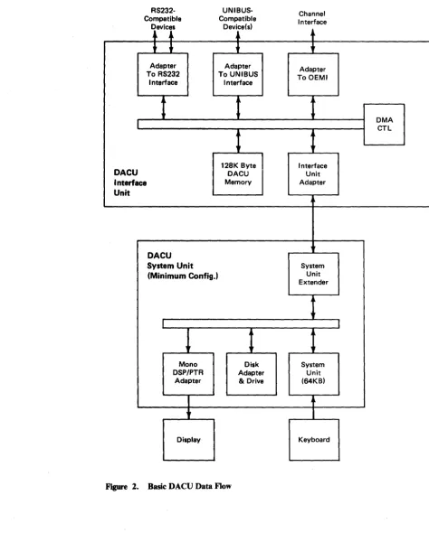
Basic Data Flow
The basic DACU data flow is illustrated below.
RS232· Compatible
Devices
l
-.-Adapter To RS232
Interface
DACU Interface Unit
DACU System Unit (Minimum Config.)
Mono DSP/PTR
Adapter
Display
UNIBUS· Compatible
Device(s)
,
Adapter To UNIBUS
Interface
t
1
128K ByteDACU Memory
t
Disk Adapter & Drive
Figure 2. Basic DACU Data Flow
Channel Interface
+
+
Adapter To OEMI
Interface Unit Adapter
System Unit Extender
System Unit (64KB)
t
Keyboard
[image:17.626.66.541.130.721.2]Communication among the functional units in the data flow is carried out on a 16-bit DACU bus.
The functional units include:
128K Byte DACU Interface Unit Memory OEMI Adapter
Parallel I/O Interface Adapter Serial I/O Adapter
Interface Unit Adapter • System Unit Extender.
The Interface Unit Adapter handles communication between the DACU Interface Unit bus and the DACU System Unit via a cable. In doing so, it manages the data buffering and coordination required to adapt the 16-bit DACU Interface Unit bus to the 8-bit data required by the DACU System Unit.
The System Unit Extender is provided for installation in DACU System Unit Expansion Slot. This card accepts the cable from the DACU Interface Unit and manages 8-bit data communication with the DACU System Unit I/O Channel.
Data Flow Unit Descriptions
DACU System Unit
The DACU System Unit is an IBM Personal Computer model 5150, or an IBM Portable Personal Computer model 5155, or an IBM Personal Computer XT model 5160 that is c.abled to the DACU Interface Unit. The DACU System Unit provides all of the processing capability required to coordinate data transfers among the DACU functional elements, including the interface adapter hardware. The System Unit controls an interface adapter by communicating commands to registers in each of the adapters. In addition, it provides the capability for developing and executing application- and device-dependent programs that participate in the coordination of data flow.
The following DACU System Unit configuration is required as a minimum to support applications in production use:
1. IBM Personal Computer System Unit with 64KB Memory and Keyboard 2. 5-1/4 inch Diskette Drive Adapter
3. 5-1/4 inch Diskette Drive
4. IBM Monochrome Display/Printer Adapter 5. IBM Monochrome Display
DACU Interface Unit
(The DACU may be powered on, initialized, and brought on-line - "enabled"-without the keyboard and display. Nor are the keyboard and display essential for production operation. They are required, however, for running diagnostic test programs and must be restored for that purpose.)
Customers may wish to configure expanded DACU System Units (e.g., additional memory) for those DACU configurations that are to be used for application code development. (For example, a customer may wish to install a configuration suitable for running the IBM PC Macro Assembler or PASCAL Compiler for application development efforts.)
Provided with the DACU Interface Unit is a diskette containing executable PC code which provides support functions for the DACU. These functions provide control (drivers) for the OEMI, Parallel I/O, and Serial I/O interface adapters; a Dispatcher function; and a linkage for customer provided code. (Default code is provided to handle common application functions for those cases where unique application- or device-dependent code is not required.)
DACU Interface Unit storage comprises 128K bytes of random access memory organized as 64K words (16 bits per word). Interface to the system data flow is via the 16-bit data bus. During alternate byte accesses of storage, the DACU System Unit will access either the left or the right byte-wide bank of RAM. During a DMA flow of data to the Parallel I/O interface under the control of an attached I/O device, both banks will communicate with the Parallel I/O interface adapter via the 16-bit system bus.
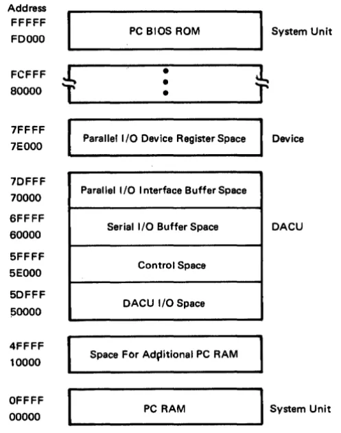
A DACU memory map is shown below, and it is followed by a brief description of
Address FFFFF
FDOOO PC BIOS ROM System Unit
t
+
FCFFF
•
•
80000
•
7FFFF
7EOOO Parallel I/O Device Register Space Device 7DFFF
70000 Parallel I/O I nterface Buffer Space 6FFFF
Serial I/O Buffer Space DACU 60000
5FFFF
5EOOO Control Space 5DFFF
!SOOOO DACU I/O Space 4FFFF
10000 Space FOr Ad~itional PC RAM
I
System Unit OFFFFPC RAM 00000
Figure 3. DACU Memory Map.
Three areas of DACU Interface Unit storage (totaling 128K bytes) plus two additional address spaces normally are used for the following purposes:
1. DACU I/O SPACE is a 56K address space associated with DACU hardware facilities (e.g., Parallel I/O interface adapter control register). (This is not a region in the DACU 128K memory; rather, it is an address space associated with DACU hardware facilities.)
2. CONTROL SPACE is an 8K area in the DACU Interface Unit memory intended to hold control blocks used by the DACU control program and for commands to be interpreted by Parallel I/O interface driver code. Each logical device has a reserved section of this memory. Control space functions are described fully in "DACU Control Space Interpreter" on page 41. In addition, a storage layout of the control space area is illustrated in "Control Space Areas" on page 62.
3. Serial I/O BUFFER SPACE is a 64K area in the DACU memory intended to be used for buffering communications to devices attached to the Serial I/O ports.
[image:20.615.196.445.87.403.2]DMA Control
OEMI Adapter
5. Parallel I/O DEVICE ADDRESS SPACE is an 8K address space associated with Parallel I/O devices. The meaning and use of specific addresses varies from device to device, and device manufacturer's documentation should be consulted. (This is not a region in the DACU 128K memory; rather, it is an address space associated with facilities in UNIBUS-compatible devices.)
Control of data flow during DMA transfers among system components is
established by the DMA control element. It computes word (two bytes) addresses. Four DMA channels are utilized.
One channel is used to refresh memory.
• One channel is utilized for communication between the OEMI adapter and RAM on a byte basis.
• Two channels are required to establish full duplex communication between the Port 1 Serial I/O adapter and RAM.
The OEMI adapter, controlled by the DACU System Unit, performs all control unit functions associated with the host I/O channel interface. It is compatible with the block multiplexer (non-data streaming) ~hannel interface on the following IBM processor models:
• IBM 4321
IBM 4331 Model Groups 2 and 11
IBM 4341 Model Groups 9, 10, 1, 11, 2, and 12 IBM 4361 Model Groups 4 and 5
• IBM 4381 Model Groups 1 and 2 • IBM 3081 Model Groups D, G, and K • IBM 3083 Model Groups E, B, and J • IBM 3084 Model Group Q.
(In the interest of brevity, when the word "host" is used in this manual, it is intended to mean one or more of the above IBM processor models.)
Flow of data involving the OEMI adapter consists of DMA transfers to DACU Interface Unit storage. OEMI transfers are byte transfers to a selected byte-wide bank of DACU storage.
Parallel
II
0 Interface Adapter
Serial
110
Adapter
Byte Coordination
The Serial I/O Adapter has facilities for serial data transfer under the control of the DACU System Unit. It utilizes byte transfers with DACU storage on a bank select basis.
In the IBM host architecture, a two byte entity (half word) is obtained by accessing the high order byte from a given storage address and the low order byte from the next address. Contrast that with the architectures for minicomputers commonly used with UNIBUS-compatible I/O devices and for the 8088 microprocessor (used in the System Unit), where the bytes are reversed. The DACU accounts for this architectural difference by coordinating the flow of bytes based on the logical device addressed on the channel (control unit, Parallel I/O interface facility, or Serial I/O port).
For a data transfer from the channel to an Serial I/O port, data is transferred into DACU storage, byte by byte. The result is that bytes in DACU storage will appear exactly in the same order as bytes in the host.
Chapter 3. Programming Considerations
The commands communicated by the host channel to the logical devices associated with the DACU must be understood if a DACU with attached physical I/O devices is to be used properly. These commands are summarized generically in the
following section.
Subsequent sections will describe the interpretations of the commands by the individual logical devices - Control Unit, Parallel I/O, Serial I/O.
In addition, the options available for host I/O programming are described. Moreover, in cases where application- or device-specific code is to be added to be executed in the DACU itself, the customer interface to DACU control programs must also be understood. This interface is described as well.
Generic Logical Device Commands
Immediately below is a generic description of the interpretation of commands by the several logical devices associated with DACU I/O device addresses.
Interpretations for the specific logical devices associated with specific addresses are described in subsequent sections.
Functionally, the DACU can be described from a number of points of view: Its behavior as a control unit and a set of logical I/O devices on the channel interface
Its behavior as perceived by an attached I/O device on the Parallel I/O interface or Serial I/O interface
Its behavior as perceived at the DACU user interface for customer-provided DACU System Unit code.
In this section, the DACU will be described in terms of its behavior as a control unit and its relationship with devices attached via the Parallel I/O and Serial I/O interfaces.
Command
No-Operation
Test I/O
Set Stop Register
Device Address 0: Control unit itself and associated DACU memory address space.
Device Address 1 : Serial Port One and associated DACU memory address space.
Device Address 2: Serial Port Two and associated DACU memory address space.
Device Address 4: Parallel I/O interface adapter and associated DACU memory address space.
Allowable commands for these four logical devices will be defined in a separate section below. However, there are degrees of common treatment of the commands by the different logical devices, and these are described immediately below.
Each of the logical devices responds to the following set of commands: Cmd
Code Description
(03) Performs no operation. Typically, the command would be used to obtain status information for the addressed logical device. In response to a No-Operation command, the DACU supplies both Channel-End and Device-End.
(00) When the host system executes a Test I/O instruction and sends it to a DACU logical device, the DACU responds with a status byte. If no status information is outstanding for the addressed device, an all-zeros status byte is returned. Any status for the addressed device is transmitted to the channel and is then reset at the end of the sequence, except for busy, which is not reset.
Command
Set Start Register
Set Address Reg.
Read
Cmd
Code Description
(27) This command initiates the transfer of two bytes from the channel to the Start Register in the DACU DCB. The two bytes (which must represent an even number between X'OOOO' and X'7FFE') are used as a host directive by all logical device control programs except the OEMI. These directives are, in essence, orders for the logical devices. Their interpretation by the logical device control programs vary, depending on the device. (Their domain and interpretation are defined in the sections following.) Channel-end status is returned to the channel on completion of the data transfer; device-end status is returned when the logical device control program completes its processing of control instructions or customer written DACU code completes execution.
(lB) Execution of this command causes the channel to send four bytes from the host system to the Address Register field in the DCB for the logical device addressed. The content of the Address Register is used to determine the offset of the starting address for a data transfer (Read or Write). Although any four-byte address can be sent, only certain address ranges may be used for data transfers, depending on the logical device. An address register value of X'FFFFxxxx' indicates that the next Read or Write will be from or to the control space for the device, which is a space reserved by the logical device control programs for control purposes. (Writes to the control space of the control program for Logical Device 0 are not allowed.) Each use of Set Address Register modifies the previous state of the Address Register.
Command
Write
Sense
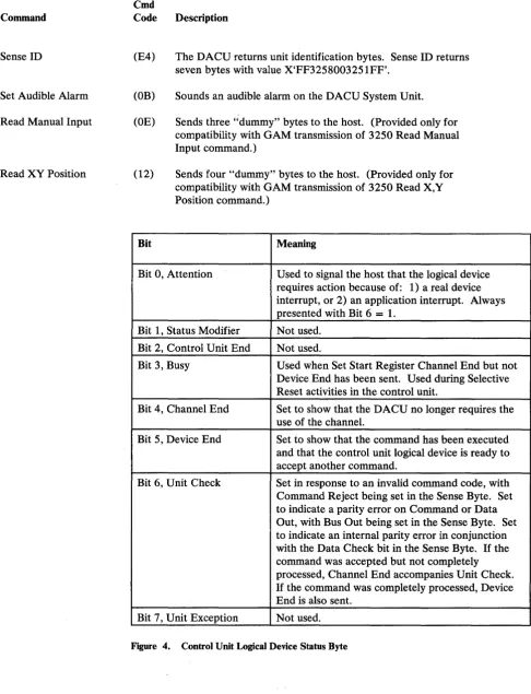
Sense ID
Set Audible Alarm
Read Manual Input
Read XY Position
Device 0: Control Unit
Cmd
Code Description
(01) Execution of a Write command will send data from the channel to the control unit address space, beginning at the address defined by the Address Register in the DCB of the logical device addressed. The Write command terminates when the channel stops sending data or when a DACU 64K byte page boundary is reached. In certain situations, the channel adapter may transfer into memory one more byte of data than sent by the host. (The data content is unpredictable.) Users should leave space between buffers for this extra byte of data when mUltiple buffers are defined for a logical device.
(04)
(E4)
(OB)
(OE)
(12)
On receipt of this command, the DACU returns four bytes of sense information to the channel. This command is accepted even if the device is in a not-ready state.
The DACU returns unit identification bytes. Sense ID returns seven bytes with value X'FF3258003251FF'.
Sounds an audible alarm on the DACU System Unit. (A different tone is associated with each logical device.) Sends three "dummy" bytes to the host. (Provided only for compatibility with GAM transmission of 3250 Read Manual Input command.)
Sends four "dummy" bytes to the host. (Provided for compatibility with GAM transmission of 3250 Read X,Y Position command and for attention pacing.) See section "Read XY-Position Required after Attention" on page 49. Status and Sense bytes are defined for each of the logical devices in sections following.
Command
No-Operation
Test I/O
Set Stop Register
Set Start Register
Valid DACU commands follow: Cmd
Code Description
(03) Performs no operation. Typically, this command would be used to obtain status information for the Control Unit. In response to a No-Operation command, the DACU supplies both Channel-End and Device-End.
(00) When the host system executes a Test I/O instruction and sends it to Logical Device 0, the DACU responds with a status byte. If no status information is outstanding for the addressed device, an all-zeros status byte is returned. Any status for the addressed device is transmitted to the channel and is then reset at the end of the sequence, except for busy, which is not reset. No initial or ending status presentations are made in response to a Test I/O.
(07)
(27)
This command transfers two bytes from the channel and loads them into a Stop Register in the Device Control Block (DeB) in the DACU. (The content of this register is not currently used by DACU control programming.) Both Channel-End and Device-End status are returned to the channel when the data transfer is complete.
Cmd
Command Code Description
Set Address Reg. (IB) Execution of this command causes the channel to send four bytes from the host system to the Address Register field in the DCB for the Control Unit. The content of the Address Register is used to determine the offset of the starting address for a data transfer (Read or Write). Although any four-byte address can be sent, only the following address ranges are meaningful for data transfers:
X'OOOOO' - X'OFFFF' 64K Section of DACU Memory for Serial I/O Data
X'lOOOO' - X'lDFFF' 56K Parallel I/O Interface Facility Address Space.
Communication of address register values of X'FFFFxxxx' are not allowed for the Control Unit Logical Device. Each use of Set Address Register modifies the previous state of the Address Register.
Read (02) This command causes the DACU to send data from the address space of the Control Unit to the channel. The starting location within the address space is determined by the content of the Address Register in DCB for the Control Unit Logical Device. The Read command terminates when the channel stops accepting data, when the control unit stops sending data, or when a 64K byte DACU page boundary is reached.
Write (01) Execution of a Write command will send data from the channel to the control unit address space, beginning at the address defined by the Address Register for the Control Unit Logical Device, The Write command terminates when the channel stops sending data, when the control unit stops receiving data, or when a 64K byte DACU page boundary is reached. In certain situations, the channel adapter may transfer into memory one more byte of data than sent by the host. (The data content is unpredictable.) Users should leave space between buffers for this extra byte of data when multiple buffers are defined for a logical device.
Command
Sense ID
Set Audible Alarm
Read Manual Input
Read XY Position
Cmd
Code Description
(E4) The DACU returns unit identification bytes. Sense ID returns seven bytes with value X'FF3258003251FF'.
(OB) Sounds an audible alarm on the DACU System Unit.
(OE) Sends three "dummy" bytes to the host. (Provided only for compatibility with GAM transmission of 3250 Read Manual Input command.)
(12) Sends four "dummy" bytes to the host. (Provided only for compatibility with GAM transmission of 3250 Read X,Y Position command.)
Bit Meaning
Bit 0, Attention Used to signal the host that the logical device requires action because of: 1) a real device interrupt, or 2) an application interrupt. Always presented with Bit 6
=
1.Bit 1, Status Modifier Not used.
Bit 2, Control Unit End Not used.
Bit 3, Busy Used when Set Start Register Channel End but not Device End has been sent. Used during Selective Reset activities in the control unit.
Bit 4, Channel End Set to show that the DACU no longer requires the use of the channel.
Bit 5, Device End Set to show that the command has been executed and that the control unit logical device is ready to accept another command.
Bit 6, Unit Check Set in response to an invalid command code, with Command Reject being set in the Sense Byte. Set to indicate a parity error on Command or Data Out, with Bus Out being set in the Sense Byte. Set to indicate an internal parity error in conjunction with the Data Check bit in the Sense Byte. If the command was accepted but not completely processed, Channel End accompanies Unit Check.
If the command was completely processed, Device End is also sent.
Bit 7, Unit Exception Not used.
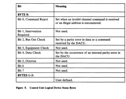
[image:30.615.76.563.69.705.2]Bit Meaning
BYTE 0:
Bit 0, Command Reject Set when an invalid channel command is received or an illegal address is encountered.
Bit 1, Intervention Not used. Required
Bit 2, Bus Out Check Set by a parity error in data or a command received by the DACU.
Bit 3, Equipment Check Not used.
Bit 4, Data Check Set by the occurrence of an internal parity error in the DACU.
Bit 5, Overrun Not used.
Bit 6 Not used.
Bit 7 Not used.
BYTES 1-3:
User defined.
Figure 5. Control Unit Logical Device Sense Bytes
Device 4: Parallel
II
0 Interface Adapter
The DACU address space associated with the UNIBUS-compatible Parallel I/O Interface Adapter (Logical Device 4) is a subset of the total DACU address space. The Parallel I/O interface address space is 64K bytes2• The first 56K (X'70000' to X'7DFFF') of this space addresses real DACU memory, and the remaining 8K (X'7EOOO' to X'7FFFF') addresses potential Parallel I/O device registers. Using I/O commands to this logical device, only the address space related to the Parallel I/O interface facility that is associated with real DACU memory (56K) may be directly addressed via channel commands. However, by executing I/O commands for the control unit (Logical Device 0), all of the available (120K - 64K for Serial and 56K for Parallel I/O) address space may be reached.
[image:31.613.122.542.57.387.2]Command
No-Operation
Test I/O
Set Stop Register
An interrupt routine exists at all times which will field a device interrupt and accept an interrupt vector from the device. If no customer written code is provided for special interrupt handling, an attention will be sent to the host system, and the interrupt vector will be passed there via sense bytes.
A description of the interpretation of I/O commands for the Parallel I/O Interface Adapter Logical Device follows:
Cmd
Code Description
(03) Performs no operation. Typically, the command would be used to obtain status information for the Parallel I/O Interface Adapter. In response to a No-Operation command, the DACU supplies both Channel-End and Device-End.
(00) When the host system executes a Test I/O instruction and sends it to Logical Device 4, the DACU responds with a status byte. If no status information is outstanding for the addressed device, an all-zeros status byte is returned. Any status for the addressed device is transmitted to the channel and is then reset at the end of the sequence, except for busy, which is not reset. No initial or ending status presentations are made in response to a Test I/O.
Command
Set Start Register
Set Address Reg.
Cmd
Code Description
(27) This command initiates the transfer of two bytes from the channel to the Start Register field in the DCB for the Parallel I/O Interface Adapter Logical Device. (These two bytes must be an even number between X'OOOO' and X'7FFE'.) Channel-End status is returned to the channel on completion of the data transfer; Device-End status is returned when the Parallel I/O Interface Adapter control program completes its processing of control space instructions or when the customer provided DACU code completes execution and issues a FAR return to DACU base code.
(lB)
A start register value of X'0006' causes the control data previously written in the control space for the logical device to be executed by a control data interpreter. (See "DACU Control Space Interpreter" on page 41.)
A Start Register value of X'0008' causes control to be passed to customer provided DACU code.
A Start Register value other than X'0006' or X'0008' will cause a warning message to be displayed on the DACU System Unit and a Device End/Unit Check to be sent to the host.
Command
Read
Write
Sense
Sense ID
Set Audible Alarm Read Manual Input
Read XY Position
Cmd
Code Description
(02) This command causes the DACU to send data from the address space of the Parallel I/O Interface Adapter Logical Device to the channel. The starting location within the address space is determined by the content of the Address Register in the adapter's DCB. The Read command terminates when the channel stops accepting data or when the end of the adapter's address space is reached.
(Ol) Execution of a Write command will send data from the channel to the adapter address space, beginning at the address defined by the Address Register for the Parallel I/O Interface Adapter Logical Device. The Write command terminates when the channel stops sending data or when the end of the adapter's address space is reached. In certain situations, the channel adapter may transfer into memory one more byte of data than sent by the host. (The data content is unpredictable.) Users should leave space between buffers for this extra byte of data when mUltiple buffers are defined for a logical device.
(04) On receipt of this command, the DACU returns four bytes of sense information to the channel. This command is accepted even if the device is in a not-ready state.
(E4) The DACU returns unit identification bytes. Sense ID returns seven bytes with value X'FF3258003251FF'.
(OB) Sounds an audible alarm on the DACU System Unit. (OE) Sends three "dummy" bytes to the host. (Provided only for
compatibility with GAM transmission of 3250 Read Manual Input command.)
(12) Sends four "dummy" bytes to the host. (Provided for compatibility with GAM transmission of 3250 Read X,Y Position command and for attention pacing.) See section "Read XY-Position Required after Attention" on page 48.
Bit Meaning
Bit 0, Attention Used to signal the host that the logical device requires action because of: 1) a real device interrupt, or 2) an application interrupt. Always presented with Bit 6
=
1.Bit 1, Status Modifier Not used.
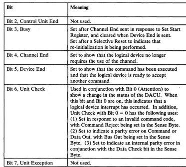
Bit Meaning
Bit 2, Control Unit End Not used.
Bit 3, Busy Set after Channel End sent in response to Set Start Register, and cleared when Device End is sent. Set after a Selective Reset to indicate that re-initialization is being performed.
Bit 4, Channel End Set to show that the logical device no longer requires the use of the channel.
Bit 5, Device End Set to show that the command has been executed and that the logical device is ready to accept another command.
Bit 6, Unit Check U sed in conjunction with Bit 0 (Attention) to show a change in the status of the DACU. When this bit and Bit 0 are on, this indicates that a logical device interrupt has occurred. In addition, Unit Check with Bit 0 = 0 has the following uses: ( 1) Set in response to an invalid command code, with Command Reject being set in the Sense Byte. (2) Set to indicate a parity error on Command or Data Out, with Bus Out being set in the Sense Byte. (3) Set to indicate an internal parity error in conjunction with the Data Check bit in the Sense Byte.
Bit 7, Unit Exception Not used.
Figure 6 (Part 2 of 2). Parallel I/O Interface Logical Device Status Byte
The conditions which can cause a Device End/Unit Check are:
• A control space interpreter loop counter exceeded. (See Section "DACU Control Space Interpreter" on page 41.)
• An invalid value in the Start Register. (Only values X'0006' and X'0008' are allowed.)
• An invalid control space operation code received.
• Customer written local code signaled a Device End/Unit Check.
Bit Meaning
BYTE 0:
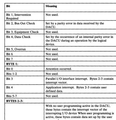
[image:35.617.89.553.18.735.2] [image:35.617.179.552.65.399.2]Bit Meaning
Bit 1, Intervention Not used. Required
Bit 2, Bus Out Check Set by a parity error in data received by the DACU.
Bit 3, Equipment Check Not used.
Bit 4, Data Check Set by the occurrence of an internal parity error in the DACU during an operation by the logical device.
Bit 5, Overrun Not used.
Bit 6 Not used.
Bit 7 Not used.
BYTE 1:
Bit 0 Attention occurred.
Bits 1-2 Not used.
Bit 3 Parallel I/O interface interrupt. Bytes 2-3 contain interrupt vector.
Bit 4 Application interrupt. Bytes 2-3 contain user defined data.
Bits 5-7 Not used.
BYTES 2-3:
With no user programming active in the DACU, these bytes contain the interrupt vector of the interrupting I/O device When user programming is active, these bytes contain data set up by the user program for return.
[image:36.623.179.559.62.455.2]Device 1 and 2: Serial
110
Ports One and Two
Command
No-Operation
Test I/O
Set Stop Register
A description of the interpretation of I/O commands for the two Serial I/O ports (Logical Devices 1 and 2) follows:
Cmd
Code Description
(03) Performs no operation. Typically, the command would be used to obtain status information for the Serial I/O Port Logical Devices. In response to a No-Operation command, the DACU supplies both Channel-End and Device-End.
(00) When the host system executes a Test I/O instruction and sends it to Logical Device 1 or 2, the DACU responds with a status byte. If no status information is outstanding for the addressed device, an all-zeros status byte is returned. Any status for the addressed device is transmitted to the channel and is then reset at the end of the sequence, except for busy, which is not reset. No initial or ending status presentations are made in response to a Test I/O.
(07)
This command transfers two bytes from the channel and loads them into a Stop Register in the Device Control Block (DCB) for the addressed Serial I/O Logical Device. (The content of this register is not currently used by DACU control programming.) BothCommand
Set Start Register
Cmd
Code Description
(27) This command initiates the transfer of two bytes from the channel to the Start Register field in the DCB for the addressed Serial I/O Port. (These two bytes must represent an even number between X'OOOO' and X'7FFE'.) Channel-End status is returned to the channel on completion of the data transfer; Device-End status is returned when the control program for the logical device completes its processing of the Start Register contents.
When a Set Start Register command is received, the Serial I/O Port control program causes the following actions to occur depending on the hexadecimal value of the two bytes communicated from the
channel: , I
'0002' - Causes the serial port to begin receiving data and transferring it into a DACU buffer area.
'0004' - Causes the serial port to begin transmitting data from a DACU buffer area.
'0006' - Causes initialization of the serial port to be performed based on control data previously written in the control space for the serial port. See "Programming for Serial I/O Devices" on page 49 for the definitions of these parameters.
'0008' - Passes control to customer-provided DACU code. 'OOOA' - Send "Break" over line.
'OOOC' - Re-initialize to power-on state.
Command
Set Address Reg.
Read
Write
Sense
Sense ID
Set Audible Alarm
Read Manual Input
Cmd
Code Description
(lB) Execution of this command causes the channel to send four bytes from the host system to the Address Register field in the DCB for the addressed Serial I/O Port Logical Device. The content of this address register is used to determine the offset of the starting address for a data transfer to page six (Read or Write). This offset is measured from the beginning of the write buffer or read buffer (frequently specified as zero). Although any four-byte address can be sent, only the address ranges X'OOOO' to X'FFFF' may be used for data transfers to the address space of a Serial I/O Port Logical Device. An address register value of X'FFFFxxxx' indicates that the next Read or Write will be from/to the control space of the Serial I/O Port Logical Device addressed. Control space can only be written to from the beginning of the area, Each use of Set Address Register modifies the previous state of the Address Register.
(02) This command causes the DACU to send data from the address space of a Serial I/O Port Logical Device to the channel. The starting location of this buffer is determined by the content of the Address Register in the Port's DCB. The read command terminates when the channel stops accepting data or when the end of the address space of the logical device is reached.
(01) Execution of a Write command will send data from the channel to the address space of this logical device beginning at the address defined by the Address Register for the Logical Device. The Write command terminates when the channel stops sending data or when the end of the Logical Device's address space is reached. In certain situations, the channel adapter may transfer into memory one more byte of data than sent by the host. (The data content is unpredictable.) Users should leave space between buffers for this extra byte of data when multiple buffers are defined for a logical device.
(04) On receipt of this command, the DACU returns four bytes of sense information to the channel. This command is accepted even if the device is in a not-ready state.
(E4) The DACU returns unit identification bytes. Sense ID returns seven bytes with value X'FF3258003251FF'.
(OB) Sounds an audible alarm on the DACU System Unit. (A different tone is associated with each logical device.)
Command
Read XY Position
Cmd
Code Description
(12) Sends four "dummy" bytes to the host. (Provided for compatibility with GAM transmission of 3250 Read X,Y Position command and for attention pacing.) See section "Read XY -Position Required after Attention" on page 48.
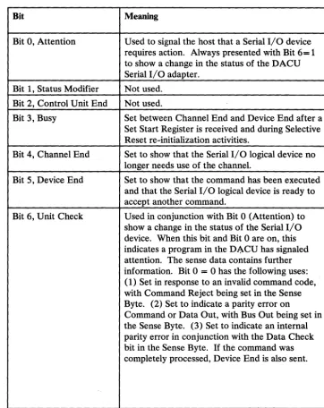
Bit Meaning
Bit 0, Attention Used to signal the host that a Serial I/O device requires action. Always presented with Bit 6= 1 to show a change in the status of the DACU Serial I/O adapter.
Bit 1, Status Modifier Not used. Bit 2, Control Unit End Not used.
Bit 3, Busy Set between Channel End and Device End after a Set Start Register is received and during Selective Reset re-initialization activities.
Bit 4, Channel End Set to show that the Serial I/O logical device no longer needs use of the channel.
Bit 5, Device End Set to show that the command has been executed and that the Serial I/O logical device is ready to accept another command.
Bit 6, Unit Check Used in conjunction with Bit 0 (Attention) to show a change in the status of the Serial I/O device. When this bit and Bit 0 are on, this indicates a program in the D~CU has signaled attention. The sense data contains further information. Bit 0 = 0 has the following uses: (1) Set in response to an invalid command code, with Command Reject being set in the Sense Byte. (2) Set to indicate a parity error on
Command or Data Out, with Bus Out being set in the Sense Byte. (3) Set to indicate an internal parity error in conjunction with the Data Check bit in the Sense Byte. If the command was completely processed, Device End is also sent.
Bit 7, Unit Exception Not used.
[image:40.629.185.547.188.644.2]Bit Meaning
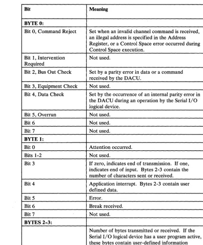
BYTE 0:
Bit 0, Command Reject Set when an invalid channel command is received, an illegal address is specified in the Address Register, or a Control Space error occurred during Control Space execution.
Bit 1, Intervention Not used. Required
Bit 2, Bus Out Check Set by a parity error in data or a command received by the DACU.
Bit 3, Equipment Check Not used.
Bit 4, Data Check Set by the occurrence of an internal parity error in the DACU during an operation by the Serial I/O logical device.
Bit 5, Overrun Not used.
Bit 6 Not used.
Bit 7 Not used.
BYTE 1:
Bit 0 Attention occurred.
Bits 1-2 Not used.
Bit 3 If zero, indicates end of transmission. If one, indicates end of input. Bytes 2-3 contain the number of characters sent or received.
Bit 4 Application interrupt. Bytes 2-3 contain user defined data.
Bit 5 Error.
Bit 6 Break received.
Bit 7 Not used.
BYTES 2-3:
Number of bytes transmitted or received. If the Serial I/O logical device has a user program active, these bytes contain user-defined information necessary to the host application program.
[image:41.627.142.548.65.554.2]Host Programming Support
110
Programming Support
EXCP Programming
GAM Programming
Host system programming must consider mechanisms for:
1. Making the DACU known to the host system control program. (For purposes of system generation, the DACU will appear to be a 2250 Model 3 control unit or "unsupported device.")
2. Creating and initiating channel programs that will communicate the I/O commands (and associated data) that will control, write to, and read from the DACU logical devices. See Appendix A, "Sample Host Programming" on page 147 for examples of channel programming code.
3. Handle attentions returned from the DACU logical devices by the channel. See Appendix A, "Sample Host Programming."
4. Error diagnosis and recovery. (See OS/VS2 I/O Supervisor Logic,
SY26-3823, or Virtual Machine/System Product System Programmer's Guide, SC 19-6203 and Appendix A, "Sample Host Programming.")
There are several mechanisms available which can be used by the system
programmer to create channel programs - EXCP or Start I/O programming and an access method.
The lowest level of DACU host system programming involves building a channel program and issuing an EXCP (Execute Channel Program - SVC 0) or a
System/370 Start I/O (SIO) instruction to execute it. (For a reference on EXCP services, see OS/VS2 MVS Supervisor Services and Macro Instructions,
GC28-0683, or IBM Virtual Machine/System Product: eMS User's Guide, SCI9-6210. For a reference on Start I/O, see IBM System/370 Principles of Operation, GA22-7000.)
The Graphics Access Method (GAM) is available in two forms:
As a constituent of Graphic Programming Services (GPS) which is supported under VS 1 and MVS
As Graphics Access Method/System Product (GAM/SP), a Program Product for VM/SP CMS.
(GAM was designed to provide facilities for users of the IBM 3250 Graphics Display System and the IBM 2250 Model 3 Display Unit.)
1. The set of DACU commands is a subset of 3250 and 2250 commands. 2. Commands which are members of the 3250 and 2250 set but not members of
the DACU set are either given command reject or are designed to simulate the 3250 command but transfer meaningless data.
It should be understood that the compatibility exists at the control unit I/O
command level. In addition, the interpretation of the commands by the DACU may be quite different from that of the 3250. (For example, the 3250 Set Programmed Function Indicators command is used to load four bytes into the DACU Address Register.) Compatibility does not exist at the level of 3250 and 2250 display orders.
The degree of compatibility that exists is useful for two reasons:
• GAM functions may be used to build and execute the channel programs required to manage the DACU even though the interpretation by the DACU and its response to the host system are quite different from those of the 3250 and 2250.
• During the I/O configuration phase of operating system generation, the DACU should be treated as though it was a 2250 Model 3.
In the context of programming for the DACU, GAM and GAM/SP provide application programs with facilities for:
• Creating buffer loads in the host processor and transmitting them to a DACU logical device
• Attention handling
• Retrieving data associated with interrupts
• Controlling a logical device (e.g., controlling buffer locations).
No explicit statement of DACU support by GAM should be inferred. Since compatibility exists in the sense described above, it is possible to use GAM to utilize functions of the DACU. However, all GAM functions are not applicable to the DACU. For example, GAM facilities that generate 3250 display orders are not relevant to the DACU.
The correspondence between the set of DACU I/O commands and the matching 3250/2250 I/O commands is indicated below:
DACU Cmd 3250
Command Code Command
No-Operation (03) Control No-Operation
Test I/O (00) Test I/O
Attention Handling
Reference Documentation
DACU Cmd 3250
Command Code Command
Read (02) Read Buffer
Write (01) Write Buffer
Sense (04) Sense
Sense ID (E4) Sense ID
Set Audible Alarm (OB) Set Audible Alarm Read Manual Input (OE) Read Manual Input Read XY Position (12) Read X,Y Position
I/O device actions may result in an attention being transmitted to the host processor. Attentions from Parallel I/O devices contain an interrupt vector indicating that a device generated an interrupt. Attentions from Serial I/O devices contain the number of bytes transmitted or received. Local code written in the DACU System Unit can also generate attentions, sending data relevant to customer applications. HALLS and HALLGE provide subroutines to handle attentions and present attention data to customer application programs. See Appendix
A, "Sample Host Programming" on page 147. Other methods of handling attentions are to use GAM or write a host interrupt handler and install it using the CMS HNDINT macro. (For reference on HNDINT, see IBM VM/SP CMS Command and Macro Reference, SC19-6209.)
The following documents may be useful when considering host I/O programming: OS/VS2 MVS Data Management Macro Instructions, GC26-3873
OS/VS2 MVS Data Management Services Guide, GC26-3875
OS/VS2 Supervisor Logic, SY26-3823
Graphics Access Method System Product Users Guide, LC33-0126
OS/VS Graphic Programming Services (GPS) for IBM 2250 Display Unit and IBM 3250 Graphics Display System, GC27-6971
OS/VS2 Graphics Access Method Logic, GY27-7260.
Sample Host Programming Techniques
dependent, and a discussion of those considerations would have to be made in the context of the devices and/or the applications.
There are three control programs with access method support for the 3250:
• VM/SP (Release 1.4 or later) • MVS
• VS1.
A DACU may be attached to systems running these operating systems. During a system generation, however, it must be identified in the same way as a 3250. (Details for system generation may be fOl!~d in the System Generation manuals for these systems. The access method of interesfiS the Graphics Access Method (GAM) that is used for support of the 3250. (It should be noted that there is no IBM programming support specifically intended to support the DACU; future changes to GAM could impact DACU operations, although these are not expected.)
It is also possible for a customer to use a customized I/O access path for the DACU, coding channel command words and using the EXCP interface provided in any of the control programs listed above (also supported in the DOS control program), or coding channel command words and executing them using the IBM System/3 70 Start I/O instruction.
The information that follows is useful in the development of programs that use either the GAM interface, the EXCP interface, or Start I/O.
An appendix contains two sample subroutine libraries, one using GAM and EXCP (HALLGE for MVS and VM) and one using Start I/O (HALLS for VM only). These subroutine libraries may be used as is or tailored to specific customer needs.
System Generation and I/O Configuration Examples
It is necessary to identify the DACU as an I/O control unit and devices to the control program. It is necessary to configure the operating system so that it recognizes a 22503 at the device addresses assigned to DACU.
A Unit Control Word (UCW) must be made active for each I/O device address associated with the DACU configuration. This is done at the host computer operator console by trained personnel. (Follow the normal procedures for your system installation.) Each of the UCWs associated with the DACU should be set for block multiplexer mode (BMPX) and UNSHARED. (Selector Mode and Data Streaming are other options THAT ARE NOT USED.) Because UCW defaults vary from system to system:, make sure that the correct options are chosen. It will be necessary to IML the system to make the new UCWs active.
DACUDEV RDEVICE ADDRESS=(400,8) ,DEVTYPE=2250
In this example, DACUDEV is the label on the RDEVICE macro, 400-407 is the range of device addresses, and DEVTYPE specifies that the device is like a 2250. There should be one RDEVICE macro for each range of device addresses.
CP will also require the definition of a control unit. For this, an RCTLUNIT macro is required similar to the following:
RCTLU4 RCTLUNIT ADDRESS=400,CUTYPE=2840
RCTLU4 RCTLUNIT ADDRESS=400,CUTYPE=2250
In this example, RCTLU4 is the label on the RCTLUNIT macro defining the control unit to support real device addresses 400-407. The control unit is defined to be like a 2840 or 2250. There should be one RCTLUNIT macro for, in this example, every 8 device addresses.
For MVS, the following macro would define a configuration similar to the one for VM above:
IODEVICE ADDRESS=(400,1),UNIT=2250,MODEL=3,PCU=01, NUMSECT=128,FEATURE=(PRGMKYBD,ALKYB2250) IODEVICE ADDRESS=(401,1) ,UNIT=2250,MODEL=3,PCU=02,
NUMSECT=128,FEATURE=(PRGMKYBD,ALKYB2250) IODEVICE ADDRESS=(402,1),UNIT=2250,MODEL=3,PCU=03,
NUMSECT=128,FEATURE=(PRGMKYBD,ALKYB2250) IODEVICE ADDRESS=(403,1),UNIT=2250,MODEL=3,PCU=04,
NUMSECT=128,FEATURE=(PRGMKYBD,ALKYB2250) IODEVICE ADDRESS=(404,1),UNIT=2250,MODEL=3,PCU=05,
NUMSECT=128,FEATURE=(PRGMKYBD,ALKYB2250)
Following the configuration of the specific control program to support the DACU, it is necessary that GAM be configured to enable it to do buffer management for what appears to be an IBM 3258 Control Unit. This is done by the process referred to as buffer table generation in, for example, the GAM / SP Users Guide LC33-0126. One example method for buffer table generation is:
BUFTABS CSECT GABBUF
GABDEV 400, 128,FEATURE=(LIGHTPEN,ANKB,PFKB) GABBUF
GABDEV 401,128,FEATURE=(LIGHTPEN,ANKB,PFKB) GABBUF
GABDEV 402, 128,FEATURE=(LIGHTPEN,ANKB,PFKB) GABBUF
GABDEV 403, 128,FEATURE=(LIGHTPEN,ANKB,PFKB) GABBUF
GABDEV 404, 128,FEATURE=(LIGHTPEN,ANKB,PFKB) GABBUF END
END
Configuring GAM
Assembly and linkedit of this macro (i.e., how to include it with the rest of the GAM generation) is control program dependent, and the appropriate GAM manual will have to be consulted.
Once the control program and GAM are properly configured, the question of how to use GAM by the application program can be considered. Again, there are control program dependencies associated with the particular GAM product being used. The coding examples below have been validated and are sufficiently general that none of the dependencies have been included. Familiarity with the use of existing access methods is assumed.
To define the DCB:
SAMPDCB DCB DSORG=GS,MACRF=(RC,WC),DDNAME=DACU, GTYPE=BASIC
To OPEN the DCB: OPEN (SAMPDCB)
To issue a GREAD or GWRITE: GWRITE DECB,BUF, SAMPDCB, OCBP
GREAD DECB,BUF,SAMPDCB,OCBP
To simply issue a GREAD or GWRITE is not sufficient to perform I/O for the DACU. (Nor would it be sufficient for the IBM 3250.) To perform a write or read with the 3250, a two byte buffer address must be set with the Set Buffer Address Register and Start (or Stop) command. GAM chains this command automatically to precede the write or read when a GWRITE or GREAD is used. However, the DACU requires a longer address than the 3250. To set the DACU Address Register, which is four bytes long, a command code different from the Set Buffer Address Register and Start (or Stop) command code is used. (The
command code - Set Address Register - is identical to the 3250 command code Set Programmed Function Indicators.) To write an address to the DACU Address Register using GAM, use the following, for example:
GCNTRL DECB,IND,SAMPDCB,BUFADDR
Here, BUFADDR is a four byte field containing the DACU address. It is only necessary to issue this GCNTRL if it is desired to change the DACU address from which a data transfer will start.
of those facilities is not recommended.) There are essentially two options when using Basic Attention Handling.
One is to write new code embodying an attention handling routine that is
recognized by GAM through the SPAR macro. The GACB pointed to in the SPAR macro must contain the entry point address for this customer written attention handling routine.
The other option for handling attention is to use the ATTNINQ macro of GAM. This allows a program to poll for device completion information or to wait for completion. The following examples apply to this mechanism:
First, define the GACB using the SAEC:
GACB SAEC EP=O,DCB=SAMPDCB,COMAREA=COMSAVE, ATTNTYP=(LP),PFKMSK=NULL
Then issue the SPAR macro: SPAR (GACB),P