PROCEEDINGS
Com
putation
Seminar
AUGUST
1951
EDITED BY IBM APPLIED SCIENCE DEPARTMENT
CUTHBERT
c.
HURD,Director
INTERNATIONAL
BUSINESS
MACHINES
CORPORATION
P R I N T E D N
590 Madison Avenue, New York 22, N. Y. Form 22-8705-0
FORE WORD
A
COMPUTATION SEMINAR, sponsored by the International Business
.I1.
Machines Corporation, was held in the IBM Department of
Education, Endicott, New York, from August 13 to August 17, 1951.
Participating in this Seminar were ninety research engineers and
scien-tists representing computing facilities which employ IBM
Card-Programmed Electronic Calculators. The discussion centered on the
mathematical and computational aspects of a variety of important
problems which have been solved on the Card-Programmed
Elec-tronic Calculator. The formal papers of the Seminar and a digest of
the ensuing discussion are published in this volume. In addition,
informal papers were presented at several valuable supplementary
sessions. Dr. W.
J.
Ec"kert presided at a session on Training of Personnel
for Computing Laboratories at which Mr. Murray Lesser, Mr. Walter
Ramshaw and Professor Frank Verzuh led the discussion. Mr. P. M.
Thompson presided at a session on the Organization of a Computing
Installation at which Mr. W. D. Bell, Dr. H. R.
J.
Grosch, and Mr.
J.
D. Madden gave short papers. Mr. E. B. Gardner presided at a
session in which there was widespread discussion of the subject of
Data Reduction. More generally, all participants in the Seminar
con-tributed generously in discussions. The International Business
Ma-chines Corporation wishes to express its appreciation to all who
CONTENTS
Application of the IBM Card-Programmed Electronic Calculator to
Engineering Procedures at The Glenn L. Martin Company - WARREN B. KOCH . . . 13 Reduction of Six-Component Wind Tunnel Data Using the IBM
Card-Programmed Electronic Calculator, Model II
IBM Card-Programmed Electronic Calculator Operations Using a Type 402-417 BB and 604-2
The Combomat
The IBM Type 604 Electronic Calculating Punch
As a Miniature Card-Programmed Electronic Calculator
General-Purpose Floating Point Control Panels for the IBM Card-Programmed Electronic Calculator
Catapult Takeoff Analysis
Computation of Loan Amortization Schedules on the IBM Card-Programmed Electronic Calculator
Techniques for Handling Graphical Data on
the IBM Card-Programmed Electronic Calculator
Calculation of the Flow Properties in an Arbitrary Two-Dimensional Cascade
Automatic Calculation of the Roots of Complex Polynomial Equations Using the IBM Card- Programmed Electronic Calculator
A Recursion Relation for Computing Least Square Polynomials over Moving-Arcs
Numerical Solution of Second-Order Non-Linear Simultaneous Differential Equations
Matrix Inversion and Solution of Simultaneous Linear Algebraic Equations with the IBM Type 604 Electronic Calculating Punch
The Determination of Eigenvectors and Eigenvalues of Symmetric Matrices
An Application of the IBM Card-Programmed Electronic Calculator to Analysis of Airplane Maneuvering Horizontal Tail Loads
Fifth-Order Aberration in an Optical System
Theory of Elastic Vibrations of Helicopter Fuselages
Machine Procedure for Computation of Elastic Vibrations of Helicopter Fuselages
- MURRAY L. LESSER.
-HARLEY E. TILLITT MARTHA KENYON BRUCE OLDFIELD.
-JOHN D. MADDEN
-PAUL T. NIMS.
-NORMAN A. PATTON KATHLEEN BERGER L. RICHARD TURNER .
-JOHN R. LOWE
17
27 33
37
48
65
-CHARLES H. GUSHEE . . . 72
- WILLIAM D. BELL . . . 77
-JOHN T. HORNER . . . 81
-JOHN GALLISHAW, JR. . 87
-GEORGE R. TRIMBLE, JR. 93
-HENRY S. WOLANSKI. . . 98
-GEORGE W. PETRIE, III. . . . . 105
-EVERETT C. YOWELL. . . '" . 112
-LOGAN T. WATERMAN 120
-RUTH K. ANDERSON. 130
-PETER F. LEONE . . . 132
PART Ie I PAN TS
ANDERSON, RUTH K., Mathematician National Bureau of Standards
Washington, D. C.
ARNOLD, KENNETH j., Assistant Professor of Mathematics University of Wisconsin
Madison, Wisconsin
AROIAN, LEO A., Chief, Computation Group Research and Development Laboratories
Hughes Aircraft Company, Culver City, California
BAUGH, HAROLD W., Electronic Scientist Computer Branch, U. S. Naval Air Missile Test Center Point Mugu, California
BELL, WILLIAM D., Vice-President Telecomputing Corporation
Burbank, California
BERKOWITZ, RAYMOND S., Associate Moore School of Electrical Engineering
University of Pennsylvania, Philadelphia, Pennsylvania
BRINKLEY, STUART R., JR., Head Mathematical and Theoretical Physics Section U. S. Bureau of Mines, Pittsburgh, Pennsylvania
BROOKS, JACK E., Principal Stress Analyst Republic A viation Corporation
Farmingdale, New York
BROOKSHIRE, JACK W., Tabulating Research Specialist North American Aviation, Incorporated
Los Angeles, California
BROWN, DONALD M., Supervisor
Mathematical Services Group, Willow Run Research Center University of Michigan, Ann Arbor, Michigan
CARTER, DAVID S., Research Associate Forrestal Research Center, Princeton University Princeton, New Jersey
CHEYDLEUR, BENJAMIN F., Chief Applied Mathematics Laboratory
U. S. Naval Ordnance Laboratory, Silver Spring, Maryland CONANT, GEORGE H., JR., Mathematician
The Perkin-Elmer Corporation Cambridge, Massachusetts COZZONE, FRANK P., Manager
Mathematical Analysis Department
Lockheed Aircraft Corporation, Burbank, California
DEUTSCH, MURRAY L., Physicist Research and Development Laboratory
Socony-Vacuum Oil Company, Paulsboro, New Jersey DEVRIES, JOHN A., Senior Stress Analyst
Propeller Division, Curtiss-Wright Corporation Caldwell, New Jersey
DUGGAN, JOHN M., Mathematician A. V. Roe, Canada, Limited
Malton, Ontario
ECKERT , WALLACE J., Director
Department of Pure Science, Watson Scientific Computing Laboratory IBM Corporation, New York, New York
Ev ANS, GEORGE W., II, Associate Mathematician Argonne National Laboratory
Chicago, Illinois
FEIGENBAUM, DAVID, Associate Research Engineer Cornell Aeronautical Laboratory
Buffalo, New York
FERBER, BENJAMIN, Senior Research Engineer Consolidated Vultee Aircraft Corporation San Diego, California
FUHRMEISTER, PAUL F., Aeronautical Research Scientist National Advisory Committee for Aeronautics
Langley Field, Virginia
GALLISHAW, JOHN, JR., Tabulating Methods Specialist Chance Vought Aircraft
Dallas, Texas
GARDNER, EARL B., Chief
Automatic Computing Unit, Data Reduction Branch' Holloman Air Force Base, New Mexico
GROSCH, H. R. j., Head
Technical Computing Bureau, IBM Corporation Washington, D. C.
GROSH, LOUIS E., JR., Associate Statistical Laboratory, Purdue University West Lafayette, Indiana
GROSS, GEORGE L., Research Engineer Grumman Aircraft Engineering Corporation Bethpage, Long Island, New York GUSHEE, CHARLES H., President
Financial Publishing Company Boston, Massachusetts
HAMMING, RICHARD W., Research Mathematician Bell Telephone Laboratories
Murray Hill, New Jersey
HARP, WILLIAM M., Section Head Refining Technical Service Division
Humble Oil and Refining Company, Baytown, Texas HEISING, WILLIAM P., Mathematician
Technical Computing Bureau, IBM Corporation New York, New York
HERGET, PAUL, Director
University of Cincinnati Observatory Cincinnati, Ohio
HILL, W. HENRY, Coordinator of Naval Aviation Stati.rtics Office of Chief of Naval Operations
Washington, D. C.
HOELZER, HELMUT, Chief, Computation Center Ordnance Guided Missile Center
Indianapolis, Indiana
HURD, CUTHBERT C., Director
Applied Science Department, IBM Corporation New York, New York
JACKSON, IRWIN E., JR., Marine Engineer
Bureau of Ships, U. S. Navy Department Washington, D. C.
JACOBSON, ARVID W., Associate Professor of Afathematics
Wayne University Detroit, Michigan
KELLY, ROBERT G., Mathematician
Applied Physics Laboratory, Johns Hopkins University Silver Spring, Maryland
KENNEDY, ERNEST C., Senior Research Engineer
Ordnance Aerophysics Laboratory, Consolidated Vultee Aircraft Corporation, Daingerfield, Texas
KOCH, WARREN B., Senior Mathematician
The Glenn L. Martin Company Baltimore,Maryland
LEONE, PETER F.
Piasecki Helicopter Corporation Morton, Pennsylvania
LESSER, MURRAY L., Methods-Coordination Engineer
Theoretical Aerodynamics Department Northrop Aircraft, Inc., Hawthorne, California
LOWE, JOHN R., Computing Engineer
Douglas Aircraft Company, Inc. Santa Monica, California
MACINTYRE, NEIL W., Administrative Assistant
Mutual Life Insurance Company of New York New York, New York
MADDEN, JOHN D., Assistant Mathematician
The RAND Corporation Santa Monica, California
MAGINNISS, FRANK j., Application Engineer
Analytical Division, General Electric Company Schenectady, New York
MCPHERSON, JOHN C., Vice-President
IBM Corporation New York, New York
NIMS, PAUL T., Staff Engineer-Research
Engineering Division, Chrysler Corporation Detroit, Michigan
PATTON, NORMAN A., Aeronautical Research Scientist
Lewis Flight Propulsion Laboratory
National Advisory Committee for Aeronautics, Cleveland, Ohio
PETRIE, GEORGEW., III, Mathematician
Applied Science Department, IBM Corporation Washington, D. C.
Seattle, Washington
RACHFORD, HENRY H., JR., Research Engineer
Humble Oil and Refining Company Houston, Texas
RAMSHAW, WALTER A., Analytical Engineer
United Aircraft Corporation East Hartford, Connecticut
RIDGWAY, ANDRESS 0., Mathematician
U. S. Navy Hydrographic Office Washington, D. C.
ROSE, ARTHUR, Associate Professor of Chemical Engineering
The Pennsylvania State College State College, Pennsylvania
SCHLIESER, WALTER C., JR., Computing Supervisor
Douglas Aircraft Company, Inc. EI Segundo, California
SCHUTZBERGER, HENRY, Supervisor
Test Data Division, Sandia Corporation Albuquerque, New Mexico
SELLS, BERT E., Turbine Engineer
General Electric Company Boston, Massachusetts
SHELDON, JOHN W., Head
Technical Computing Bureau, IBM Corporation New York, New York
SHIPMAN, JEROME S., Mathematician
Laboratory for Electronics, Incorporated Boston, Massachusetts
SMITH, CHARLES V. L., Head
Computer Branch, Office of Naval Research Washington, D. C.
SMITH, ROBERT W., JR., Mathematician
U. S. Bureau of Mines Pittsburgh, Pennsylvania
SOWERS, NELSON E., Mathematical Data Analyst
Army Field Forces Board 4 Fort Bliss, Texas
THOMAS, L. H., Senior Staff Member
Watson Scientific Computing Laboratory, IBM Corporation New York, New York
Tf{OMPSON, PHILIP M., Head
Computing Laboratory, Hanford Works, General Electric Company Richland, Washington
TILLITT, HARLEY E.
U. S. Naval Ordnance Test Station, Inyokern China Lake, California
TRIMBLE, GEORGE R., JR., Mathematician
VERZUH, FRANK M., Director of Statistical Services
Massachusetts Institute of Technology Cambridge, Massachusetts
VIALL, JOHN, Supervisor
IBM Computing Installation, Douglas Aircraft Company, Inc. Long Beach, California
VON HOLDT, RICHARD, Staff Member
University of California; Los Alamos Scientific Laboratory Los Alamos, New Mex:co
WADDELL, WILLIAM L., Group Engineer
Computation Analysis, Northrop Aircraft, Inc. Hawthorne, California
WALKER, JOHN H., Mathematician U. S. Naval Proving Ground
Dahlgren, Virginia
WATERMAN, LOGAN T., Chief of Flutter and Vibrations
Fairchild Aircraft Division
Fairchild Engine and Airplane Corporation, Hagerstown, Maryland
WELMERS, EVERETT T., Chief of Dynamics
Bell Aircraft Corporation, Niagara Falls, New York
WEST, GEORGE P., Aeronautical Research Scientist
Ames Aeronautical Laboratory
National Advisory Committee for Aeronautics Moffett Field, California
WHITE,
J.
HUNTER, JR., MathematicianApplied Science Department, IBM Corporation New York, New York
WHITE, LAWRENCE L., Mathematician
IBM Unit, U. S. Air Force Flight Research Laboratory Dayton, Ohio
WITT, EDWARD C., Mathematician
K-25 Plant, Carbide and Carbon Chemicals Corporation Oak Ridge, Tennessee
WOLANSKI, HENRY S., Aerophysics Engineer
Consolidated Vultee Aircraft Corporation Fort Worth, Texas
YOWELL, EVERETT C., Mathematician
Application of the IBM
Card-Programmed Electronic Calculator to Engineering
Procedures at The Glenn L. Martin Company
WARREN
B.
KOCH
The Glenn
L.
Martin Company
THE PUR P 0 S E of this paper is to describe the most important engineering problems that have been adapted for processing on the IBM Card-Programmed Electronic Calculator at The Glenn L. Martin Company. However, before starting upon any such discourse, it is advisable to consider first the tools of operation-in this case, the type of control panels that are in use.
I t has been found necessary to design only two control panels for the CPC, the operations available from one or the other proving adequate to cover all needs up to the present time. They are a floating decimal type with seven-digit capacity and a fixed decimal with six-seven-digit capacity. Of course, it would always be advantageous to program jobs on a floating decimal setup, but because of the addi-tional complications involved in wiring such a control panel, fewer operations are available than on a fixed decimal design.
The operations programmed on the floating decimal con-trol panel include only addition, subtraction, multiplication, division, and square root, while the fixed decimal control panel allows for all these operations in addition to that of substitution of an argument into a polynomial of at most the fourth degree. This latter operation works in conjunc-tion with a selecconjunc-tion which makes it possible to select any one of a number of polynomials, depending upon the magni-tude of the argument used. This type of operation is par-ticularly valuable when it is necessary to approximate graphical data with polynomials, and different equations must be used over certain ranges of the curve.
FLOATING DECIMAL JOBS
Simultaneous Linear Algebraic Equations
We shall now consider the more or less routine jobs that have been adapted for the floating decimal control panel. The first of these is the solution of simultaneous linear alge-braic equations. The method used is essentially the
Gauss-13
Jordan method resulting in a unit diagonal matrix. Since the floating decimal setup is used, no attempt has been made to select the largest terms as divisors; rather, these operator coefficients are selected down the main diagonal. The solution is substituted back into the original equations and, when necessary, the errors thus resulting are operated upon to obtain corrections to the original results.
Flutter Analysis
The only type of flutter analysis which has been thus far investigated is that of determining the critical flutter speed of any aircraft; that is, the speed at which the damping of the structure is attained. This job is laborious in that it involves the expansion of a number of determinants of order equal to the number of degrees of freedom for which the aircraft is designed. The Dynamics Department has lim-ited the size of these determinants to fourth order through various simplifying assumptions, but a setup is now being evolved which will handle sixth order determinants on the CPC. The result of an expansion of one of these determi-nants is a polynomial with complex coefficients of degree equal to the order of the determinant.
A method has been devised of applying the CPC to the solution of any polynomial with coefficients either properly complex or real. Because of the limitations of storage, the system has been designed for polynomials of degree no more than eight. The mathematical technique involved is Newton's method. Up to the present time, no difficulty has been realized in obtaining any roots-in fact, the number of iterations required to obtain six-digit accuracy in the root usually has been less than twenty.
Vibration Frequency Analysis
bend-ing-torsion vibrations. The calculation is initiated by first dividing the beam into sections with discrete masses con-centrated at each station and then describing these stations by series of matrices.a
The matrices are written with the frequency factor, K, as a variable. Then, by simply multiplying the proper coeffi-cients by any value of K, the problem may be processed for any particular frequency. The routine is simply one of trial and error, where a value of K is substituted, and the asso-ciated matrices of successive beam stations are continually premultiplied until a final matrix equation is obtained re-lating the boundary conditions on both ends of the vibrating beam. The imbalance of any chosen end condition is plotted against K and the process repeated for a new value of K until a K is found which gives no imbalance. The K result-ing in this balance condition determines the vibratresult-ing fre-quency desired. The machine calculations begin after the matrices have been written and cover the substitution of the K values, the matrix multiplication, and the determination of the imbalance between end conditions.
Transfer Functions
Quite extensive use of the CPC has been made in the formulation and evaluation of transfer functions in the in-vestigation of dynamic stability of guided missiles. The transfer function of any component is essentially its equa-tion of moequa-tion expressed in differential operator form as the ratio of the input to the output. The closed loop stability characteristics can be determined from the so-called Nyquist diagram obtained from the evaluation of the transfer func-tion. For a sinusoidal input, the phase anJ amplitude of the output are plotted in the complex plane as a function of frequency. The stability is determined as a function of the encirclements of the - 1 point on the real axis.
For the airframe itself, any transfer function (such as a function of elevator, roll as a function of aileron, etc.) is completely determined by the flight condition and aero-dynamic properties as determined in a wind tunnel. A CPC
p~ocedure has been set up to accept this type of data in order to formulate any transfer function describing the missile dynamics. The transfer functions of other compo-nents (servos, amplifiers, valves, etc.) are determined by either analysis or test.
Given the transfer functions of n consecutive components in a control system-call them Ai, where i
=
1, ... , n-another procedure on the CPC obtains the response as a function of frequency of not only each component Ai but also of the products Al X A2 , Al X A2 X As, . . . ,Al X A2 X ... X An.
aThe method of developing these matrices has been fully described in an article in the October, 1947, issue of the Journal of the Aero-nautical Sciences by W. P. Targoff entitled "The Associated Mat-rices of Bending and Coupled Bending-Torsion Vibrations."
FIX:eD D:eCIMAL JOBS
Simultaneous Ordinary Differential Equations
The most important use of the fixed decimal control panel, and in fact of the CPC itself, has been in the solution of simultaneous ordinary differential equations. This prob-lem has become one of frequent occurrence with the en-trance into the guided missile field and its attendant prob-lems of automatic control and trajectory computations. Of course, this problem occurs within other problems but, by far, the preponderance of work done on the CPC at The Glenn L. Martin Company has been concerned with trajec-tory calculations.
A stepwise method is used to solve the equations with values of the dependent variables at the beginning of each step determined by quadratic extrapolation from previous information. These extrapolated values are then improved upon later by a single iteration and the difference between extrapolated and iterated values compared. This error is used to determine the maximum allowable interval into which the independent variable may be divided and also serves as a check on the machine calculations.
There is almost no limit on the number of equations (or dependent variables) that may be handled simultaneously, and there is no problem in taking care of complicated non-linearities in the coefficients.
Recently, a trajectory has been calculated at The Glenn L. Martin Company in which three distinct rectangular co-ordinate systems, each in three dimensions, were handled simultaneously. It was necessary to write a set of 76 equa-tions to describe the system completely. Of these, about one-third were differential equations, and the rest were either simply definition or angular resolution equations. Of course, it was impossible to store all values of the dependent variables; so it became necessary to summary punch many of them and reload them into the machine at various times in the following interval. This was done by prepunching decks of summary cards with operation instructions and then merely running the deck of program cards through the 402 once, replacing the pertinent cards with newly punched summary cards and continuing this process until a com-plete trajectory was calculated. Under this system, it was possible to go through one complete cycle of processing about 400 cards through the accounting machine, reloading the new summary cards and starting to process again in five minutes. A complete solution required approximately 80 machine hours and described 13 seconds of flight time. Manually, this job would have taken some 3,000 hours.
Analysis of a Cabin Conditioning System,
S E M I N A R
devised. This method, although applied to just this one sys-tem, should have extended application, and it can be tied in exceedingly well with CPC methods. This is so because the system is basically one of trial and error, where each trial involves a lengthy calculation on a small amount of data.
The system contains essentially a primary compressor, secondary compressor turbine unit, two heat exchangers, a water separator, two combustion heaters and fans, and vari-ous ducts, valves, and control mechanisms. The primary problem is the establishment of criteria for determining an unique set of operating points for the various components. The only parameter known is the primary compressor im-peller speed. All other compressor variables are unknown; furthermore, the performances of the secondary compressor and turbine are dependent on each other, and the perform-ances of this entire unit and the primary compressor unit are dependent on each other. Therefore. the performance of the entire system cannot be predicted by any straightfor-ward method of calculation, and a trial-and-error system must be adopted.
The method most frequently used in this type of problem is to assume several values of each of the independent vari-ables, and calculate the performance until the values chosen satisfy the equilibrium criteria. However, because of the wide variations of the conditions of flight, and because of the customary use of various automatic limiting devices which arbitrarily change the functional configuration, it is felt that this simple trial-and-error method is unsatisfactory. Rather, several values of two arbitrarily chosen variables are assumed in a systematic relationship so that existing trends become apparent. In addition, if the various assumed operating points bracket (or nearly bracket) the actual operating point, this point can be established with accept-able accuracy.
The CPC is particularly suited to this procedure, since a few points may be computed rapidly and then any desired re-trials may be run by simply changing a few load cards.
Wind Tunnel Data Reduction
Until recently, all wind tunnel data reductions have been calculated on the IBlV[ Type 604 Electronic Calculating Punch. It has been found that the CPC can be adequately adapted to this calculation with a resultant time saving of 60% over the 604.
All computations, with the exception of the correction of forces and moments for residual balance readings, are per-formed on the CPC. This initial correction is obtained more conveniently on the 604. The remaining calculations in-clude:
1. Converting the force and moment data to coefficient form.
2. Correcting these coefficients for:
15
a. Tare and interference, which is the influence ex-erted on the model by the supports and support fairings.
b. Alignment, or inclination of the wind stream to the balance system.
c. Effect of the constraint of the wind tunnel walls. d. Buoyancy, which is the effect of fore and aft
pres-sure gradients in the tunnel.
All of the data required to apply these corrections are determined by exacting wind tunnel testing, and the correc-tions applied in equation form to the aerodynamic coeffi-cients.
These corrected coefficients lie in a wind axis coordinate system with the origin at the point of attachment between model and support. The coefficients are finally transferred to two other coordinate systems: (1) the wind axes with origin at the center of gravity of the model, and (2) the stability axes.
Aeroelastic Influences on Control Surface Effectiveness
The aeroelastic problem is concerned with the loss of effectiveness of comrol surfaces, including ailerons, flaps and elevators, because of the elastic deformations of wing fuselage and tail. The deformations are brought about by both the twisting and bending of these various parts, which are due to angle of attack and deflection of the control surfaces.
Twisting is brought about by the fact that the chordwise centers of pressure of loads which are due to control surface deflections and angle of attack are not located at the elastic axis, thus producing powerful torques which tend to twist the wing or tail surface and change the effective angle of attack. This twisting, in turn, produces loads which further influence the elastic deformation of the wing or tail.
The problem is one of iteration since, to begm with, the final spanwise twist distribution cannot be predicted accu-rately. A twist distribution must be assumed, the torques which are due to this twist and basic loads must be com-puted, and a new twist distribution is determined from these torques. \Vith this new twist distribution, the problem is started anew, and the same steps are carried out to find a third twist distribution, and so forth, until the solutions converge to a final twist distribution.
Once the nature of the twist curve is determined, the problem becomes simple and straightforward. Now the load distributions, caused both by the basic load moments and the moments resulting from the twist distribution loads, are computed accurately by the \N eissinger method.
procedure. There are only about two hundred cards con-taining data that must be changed for different configura-tions, and these are specially coded so that they may be changed readily between jobs. This system, which takes about four hours per configuration, has replaced a proce-dure that usually required three weeks to complete by hand-computing methods.
DISCUSSION
Mr. Von H oldt: At Los Alamos we punch out eight dif-ferent numbers and put the instructions in 1 to 10 auto-matically. They are in the instruction deck and go into the summary punched card; so it is not necessary to have pre-punched cards.
Dr. Brown: When you mentioned the 80 hours of run-ning time on the machine, Mr. Koch, how did that compare with the number of hours it would have taken by hand operations?
Mr. Koch: It would have taken 3,000 hours.
Mr. Lowe: If I understood you correctly, you extrapolate in your trajectory programming with some quadratic ex-trapolations involving a prior point. Is that correct, or do you use two prior points?
Mr. Koch: We use two prior points.
Dr. Yowell: I am very much interested in some of the systems you say you have handled with more than eight differential equations at a time, where you have had to punch out the results from one step to the next and put them back in again. Has it been necessary to punch more than two cards with the same values on them?
Mr. Koch: Yes, it has. Occasionally we have had to punch the same value in a number of different cards to be used at different places in the calculation.
Mr. Lesser: \\lith regard to summary punching multiple cards from the same set of data, the technique that we used was to bring out the 12-impulse from the digit-emitter in the summary punch back through the summary punch X control wires to the accounting machine through a latch selector on the accounting machine, and then back through a second summary punch X control wire to pick up punch selectors. On additional summary punch cycles, the punch selectors caused the data to be gang punched from the lower brushes back to the punch magnets as many times as we desired.
Also I was wondering if you have done any investigating so that, instead of having to predict the next stop, you use a much simpler form of numerical analysis and just take your intervals a little closer together.
Mr. Koch: No matter how small the intervals are made, we always have to predict.
Dr. Grosch: I would like to suggest the possibility of increasing rather than decreasing the interval, for this reason: The steps of l\fr. Koch's procedure take him about five minutes; so this looks like something of the order of 1,000 steps he has to go through in his 80 hours. But sup-pose we could decrease the number of steps tenfold by tak-ing the interval ten times as large, at the expense of havtak-ing to store more data for the extrapolation. For instance, if you have nine space intervals you might have to store four or five extra orders of differences for each one of those nine, i.e., 36; and that might mean punching out twenty or thirty extra summary cards, which will take up ten or twenty per cent extra time per step. But if you have reduced the number of steps tenfold, you still have a gain of eightfold in your time of running, and cut down from 80 hours to ten hours.
It is true that the programming will be more complex, and it is also true that every time you get a discontinuity you are going to have more trouble in getting past. But I think you are more likely to get more results out of your machine by increasing the interval than by decreasing it. Dr. Thomas: I would like to warn people that while what Dr. Grosch has said is likely to be very true for computa-tions which are carried to great accuracy, like astronomical computations, it is not at all likely to be true for calculations which do not have to be carried to such great accuracy, like trajectory problems. If you are only going to something like a tenth of a per cent to start with, then the optimum interval for simple formulas is not going to be very greatly increased by using more complicated formulas.
Reduction of Six-Component Wind Tunnel Data
Using the IBM Card-Programmed Electronic Calculator.}
Model
[[*
MURRAY
L.
LESSER
Northrop Aircraft, Inc.
T EST D A T A taken during a wind tunnel program on a scale model of a Northrop airplane, conducted in the ten-foot pressure tunnel at Wright-Patterson Air Force Base, were reduced to coefficient form using the IBM Card-Pro-grammed Electronic Calculator, Model II. Six-component test dataa for each test point were key-punched into a single
IBM card (average key punch time was approximately 75 test points per hour). The data cards were machine collated into a prepared program deck, and the results were com-puted and printed in coefficient form for both stability and wind axes (simultaneously) in one pass through the calcu-lator at a rate of three test points per minute. Because of the nature of the balance system and the small size of the model relative to the tunnel, corrections were not required for tares or wall effects.
The programming and wiring of the CPC for this com-putation are discussed in more than usual detail as an illus-trative example of the flexibility available in the CPC Model I1.b This flexibility allows parallel-serial operation
of the calculator where a small number of digits will carry the required information. With few exceptions, the compu-tations required are elementary, and no originality is claimed for the manner in which they are accomplished.
It should be pointed out that the machine time for an equivalent computation on the CPC Model I would have been approximately twice as long. Also, it would have been necessary to split the key-punched data for one test point into two cards, thus increasing the possibility of error through operator mishandling as well as increasing the key-punch time.
aData key-punched into the card consisted of the six wind tunnel strain gage readings, the uncorrected angles of attack and yaw, the tunnel dynamic pressure, and an identifying run number.
bIt should be noted that the discussion on machine operation (Sec-tion II) assumes a speaking knowledge of IBM computing tech-niques on the part of the reader; in particular, familiarity with the concepts of the CPC Model I is implied.
17
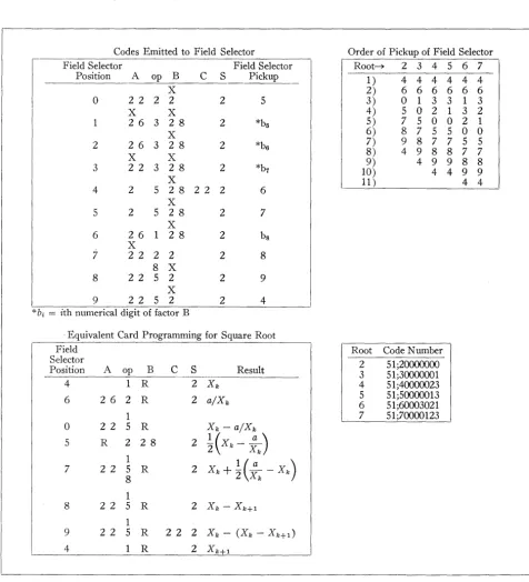
1. DATA REDUCTION FORMULAS
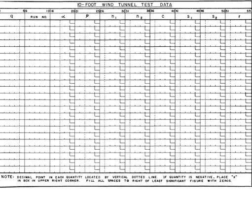
The test data are recorded, from a strain gage balance system located in the sting mount, in the form of readings on a Brown self-balancing potentiometer. In order to elimi-nate tares and effects of battery voltage variation, a "zero" reading for each strain gage is subtracted from the particu-lar reading before the point is recorded on the key-punch form (Figure 1). The recorded values, as entered on the form, are the net strain gage readings divided by 100. The six-component data are recorded from the balance system in the form of forward and rear normal force gage readings, nl and n2, respectively; chord force reading, c; forward and rear side force readings, Sl and S2; and a rolling moment reading, r. The associated loads are obtained from the fol-lowing calibration data:
Nl
=
316.0 nl (lb.) N2 80.0n2 (lb.)C'
=
31.7 c (lb.)Sl
44.2 Sl (lb.) (1)S2
22.9 S2 (lb.)R
=
446.0r (in.-lb. )In addition to the chord force determined directly from the reading of c, it was found during the calibration tests that there existed interaction effects on c because of the other loads. Hence, the net chord force, in pounds, is given by the folio wing expression:
C
=
C'+
0.0116 Nl+
0.0050 N2+
0.011Sl
+
0.022 R+
0.888tf! .
(2) The value oftf!
used above is the preset value,tf!u,
cor-rected for deflection in the mounting system due to air-loads. Calibration tests provided the following correction10- FOOT WIND TUNNEL TEST DATA
I 56 1016 2C 21 2f~6 3C 31 3536 4C 41 4546 5051 55
q RUN NO. 0( It'
n
ln
2 C 51 52 rL i L I L
I L
L : L L L
L L L L L L I
L I
L I
L L I L L L I
L I L L
I
I I
L L I
1- L L L L L
I
L L I L L L L L L
L L I L L
I L L L L
I
L L_ I L L L L L L
I
I
L L I
L L L L L L
i L L I I L
!
L L L L LL L I L
I L L L L L
L L I I- L L L L L
L L L L L L L L
I
L L L L L i L L L
1- L i L I L L L L I L
I
L L L L I L L L L
:
L
1
L L L L
!
L L LL L L L L L L L
L : L L L L L L L
I
L L L L L L L L
i
L L L L L L L L
1- L L L L L L : L
:
L L L L L L L L
L L L L
!
L L L LNOTE: DECIMAL POINT IN EACH QUANTITY LOCAT.ED BY VERTICAL DOTTE 0 . LINE. IF QUANTITY IS NEGATIVE. PLACE "X"
[image:17.613.57.568.85.485.2]IN BOX IN UPPER RIGHT CORNER. FI LL ALL SPACES TO RIGHT OF LEAST SIGNIFICANT FIGU.RE WfTH ZEROS.
FIGURE 1. TEST DATA FORM
expressions for the angle of attack, ~, and the angle of yaw, ""in degrees:
~
=
~u+
0.0016N2+
f(N1 )feNd = 0.0022 N1 (for N1
>
0)=
0.0032 N1 (for N1<
0)t/t
=
t/tu
+
0.0028 S1+
0.0020 S2.(3)
From the geometry of the model and balance system, and the conventional definitions of the aerodynamic forces and moments, the following' expressions are derived:
A. Stability Axes
(4)
Lift
==
Ls
=
(N1 +N2 ) cos~ - Csin~ (lb.)Drag
==
Side force
==
Ds = Ccos~+ (N1 +N2 ) sin~ (lb.)
Ys = S1
+
S2 (lb.)Pitching moment
==
Ms=
-0.169 Nl - 9.581 N2 (in.-Ib.) Yawing moment==
ns = (-1.134 S1 - 10.546 S2) cos ~- R sin ~ (in.-Ib.) Rolling moment
==
ls=
(-1.134 S1 - 10.546 S2) sin ~S E M I N A R
B. Wind Axes
Lift == Drag== Side force ==
Lw = Ls
D w
=
D s cos tf;+
Y s sinif;
Yw
=
Ys cos tf; - Dssintf;Pitching moment == M w
=
M s cos tf;+
ls sin tf;Yawing moment == nw = ns
Rolling moment == lw
=
l8 cos tf; - M 8 sin tf;(5)
The aerodynamic coefficients are determined from the airloads in the conventional manner.
where
CL = LjqSw CD = D/qSw
Cy = YjqSw CM
=
JJ1jqSwc
Cn = njqSwb
Cz
=
l/qSwbq = Dynamic pressure (lb./ft.2 )
S
w = Model wing area (fL 2 )c
= Model mean aerodynamic chord (in.)b = Model span (in.).
(6)
All numerical values are carried in five-digit (plus sign) counters. The lift force and all moments are computed to one decimal place, the chord and side forces to two decimal places, and the angles of attack and yaw to three decimal places. The final coefficients are presented to four decimal places (a maximum of five significant figures in all cases).
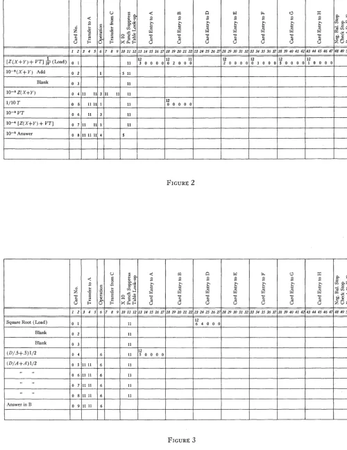
II. COMPUTATION PLANNING CHART
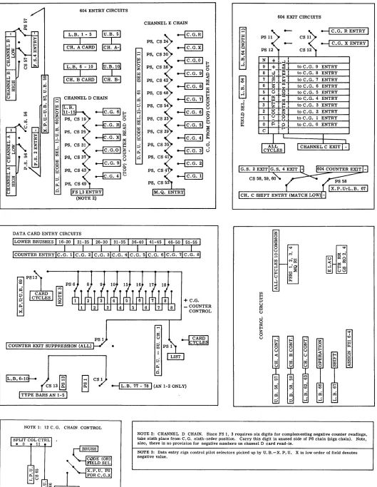
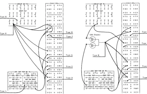
Detailed planning of the computation was carried out di-rectly on the program-deck key-punch form in the normal CPC manner. This planning sheet is shown in Figure 2. However, before such a planning sheet could be prepared it was necessary to establish the desired characteristics of the particular computing machine to be used for the problem. By this is meant that through proper design of the control panel wiring, a card-programmed calculator having the par-ticular arithmetic and transfer properties best suited to the problem at hand was constructed from the available units in the CPC Model II. The process of design for this problem was somewhat as follows.c
Since all of the numerical values to be computed would be limited to five significant figures, the counters of the IBM Type 417 Accounting Machine, Model AA, could be divided into 12 six-digit counter groups, each having a capacity of five numerical digits plus sign. (Note: Four counter groups, counters 8A, 8B, 8C, and 8D, each have a
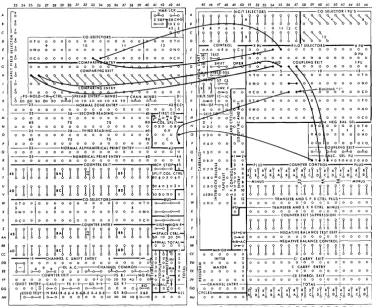
cSchematic wiring diagrams of the Type 417 circuits are shown in Figures 3A and 3B, pages 21 and 22. Definitions of the notation used are given in Figure 3B.
19
capacity of seven digits plus sign. The unused digits are not wired to the entry or exit chains.) The use of 12 counter groups was also suggested by the fact that there are twelve items (exclusive of run number) to compute and print for each point: ex, tf;, CL , Cn, and two values each of CD, Cy , CM, and
C
z• Also, twelve is the maximum number of countergroups that can be controlled by punchings in a single card column, by numbering the counter groups from 0 to 9 and X and R.d Thus, control of a given counter group for any function desired (read-out, read-in, reset) e could be ef-fected by splitting time pulses from punchings in a single card column, for each function, through a coding selector (for the digits) and a pair of co-selectors picked up by the split column controls (for the X and R impulses). Sche-matic diagrams of the various counter control circuits are shown in Figures 3A and 3B, pages 21 and 22.
Inspection of equations 2, 3, 4 and 5 indicate that most of the arithmetic operations involved may be put into the forms
Fl
=
alX+
b1'YF2
=
a2't' - b2y, (7)where the a's and b's are either constants or trigonometric functions of variables, and the x's and y's are the variables involved in the equations. Consequently, the entry selector chains, i.e., the relay paths or channels over which informa-tion is transmitted from specified 417 AA counter groups to the 604 Electronic Calculator (the arithmetic unit of the CPC), were designed with these two functions in mind. The two built-in channels, A and B, are used only for entry of constants from cards in the program deck, or of factors from the storage register (where the needed sines and co-sines are stored as computed). Channels D and
E
are made up from selector chains to carry information from the 417 AA counters. Card read-in (positive numbers only) is also available on channel D. 'rhe "normal" control proce-dure for reading information from the storage registers(16 registers of ten digits plus sign) over channels A and B is modified to allow choice of either the five low-order digits (with sign) or the five high-order digits (positive numbers
(Continued on page 23)
dOver-punches referred to as X and Rare 11 and 12 punches, re-spectively.
1
O.
O.
.0
2
~
Card R.I. Card R.I. CardR.I. Inst. Inst. Inst. Inst. Inst. Inst. 0'
2 3 4 5 6 7 8 9 10 11 12 13 14 15 . 56 57 58 59 60 61 62 63 64 65 66 67 68 69 77 78 +-Card Column No.
+. + Sw
+ -I- 0 0 0 0 1 7 3 1 X 0 1 Load qSw & Data (1)
+ 7
1 8 X 5 0 2 Load Run No.
3. 1 6 0 0 0 3 9 3 3 1 0 3 Nl
.8 0 8 0 0 4 0 4 3 1 0 4 N2
.3 1 7 0 0 0 5 X 5 3 1 0 5 C'
.4 4 2 0 0 0 6 R 6 3 1 0 6 SI
.2 2 9 0 0 0 7 3 7 3 1 0 7 S2
4. 4 6 0 0 0 8 4 8 3 1 0 8 R
O. 0 0 1 6 0 0 0 1 3 3 0 9 ~al
0 0 2 2 O. 0 0 3 2 0 0 0 0 9 1 2 3 1 0 ~a2=[F(Nl)1
0 0 2 8 O. 0 0 2 0 0 0 0 0 R 3 2 3 2 1 1 ~.p
1 7 4 5 3 1. 0 0 1 2 7 1 X 1 2 cos a, sin a
5
1 7 4 5 3 1. 0 0 2 2 8 1 X 1 3 cos.p, sin.p
5
1 1 6 0 .0 0 5 0 0 0 0 0 0 9 0 X 3 1 1 4 ~Cl
.0 1 1 0 .0 2 2 0 0 0 0 0 R 3 X 3 1 1 5 ~C2
2 0 0 0 .8 8 8 0 0 0 0 0 4 2 X 3 0 1 6 ~C3
1- 1. 0 0 0 0 9 0 5 3 5 1 7 N.l+ N2
.1 6 9 X 0 9 .5 8 1 X 0 0 0 0 0 9 0 6 0 3 1 1 8 Ms 9
2 7 5 0 3 2 1 9 (N, + N 2) sin a
2 X X 0 3 1 2 0 Ccos a (Ds)
7
2 X 5 8 5 5 1 2 1 (N, + N 2) cos a 7
2 7 X 8 X 5 0 2 2 - Csina (Ls)
1. 1. 0 0 0 0 R 3 X 3 5 2 3 SI + S2 (Ys)
1- 1 3 X 4 1 0 .5 4 X 0 0 0 0 R 3 R 3 1 2 4 - (1.134S 1 + 1O.546S2 )
6 9 3
2 8 2 X 8 0 X 1 1 5 1 2 5 Y w
1 7 8 3 8 4 5 2 6 CL
2 7 2 X 4 9 R 5 1 2 7 n
7
2 X 7 2 7 4 9 8 4 3 1 2 8 ls
9 C
.+ + 1 7 1 6 3 2 2 9 qSwc
+
b + .+ 1 7 1
5 3 3 3 0 qSwb
+
2 X 2 8 6 8 1 2 3 1 3 1 Mw 8
2 8 2 X 6 8 1 3 5 1 3 2 lw 8
2 X 2 8 0 X 1 4 3 1 3 3 Dw 8
1 7 0 4 0 4 4 3 4 CDs
1 6 6 5 6 4 4 3 5 CMs
1 7 X 6 X 4 4 3 6 CYs
1 5 8 7 8 4 4 3 7 Cis
1 5 R 8 R 4 4 3 8 CII
1 3 1 5 9 6 4 3 9 Olw
1 2 1 6 0 6 4 4 0 CMw
1 4 1 7 X 6 4 4 1 'ClJw
1 1 1 7 R 6 4 4 2 CYw
X 4 3 Print
X 8 0 0 Compare Run No.
1
Note 1. The information on program-deck card 1 is gang punched into all the data cards key punched from Figure 1. These cards are collated into the series of program decks (using X-59), and become, in turn, card 1 of each program deck.
FIGURE 2. PROGRAM-DECK KEY PUNCH FORM
604 ENTRY CIRCUITS
~
CH.A-C»
It)
~
CH.B-j:Q
:;:)
t-~
CHANNEL D CHAIN It) ;:::<
:g
~~
0 00
~~
~~~
~ ~§3. 0 f;I;:I ~:: ~0 p.
g. 0
::i ~e
p; ci
DATA CARD ENTRY CIRCUITS
COUNTER EXIT SUPPRESSION (ALL)
;:::< f;I;:I E-< 0 Z f;I;:I f;I;:I $ .... co ~ ~ 'c::i' J f;I;:I rJJ f;I;:I ~ 0 g. ::i p; ci
CHANNEL E CHAIN
PS, CS 24 PS, CS 30 PS, CS 3.6 PS, CS 42 PS, CS 48 PS, CS 54 PS, CS 23
~ ~
~~
0~~
~ ~~ f;I;:I~~
0 t.) ~~ 0 E-<~i
0 ~~ d c.>+ C.G. _ COUNTER
CONTROL
604 EXIT CIRCUITS
;:::< f;I;:I E-<
~
~ co!Xi N
...:i 9 to C.G. 9 ENTRY
to C.G. 8 ENTRY
~
7 to C.G. 7 ENTRYto C.G. 6 ENTRY 5 to C.G. 5 ENTRY 4 to C .• G. 4 ENTRY
...:i to C.G. 3 ENTRY
f;I;:I rJJ
to C.G. 2 ENTRY
B
to C.G. 1 ENTRY f;I;:I~ 0 to C.G. 0 ENTRY C
z
0
~
~ ~ '<I'
t.)
.,.) ~N
~
rJJ N~ ~O
f;I;:I
... (1 ~~
...:I E-<rJJ
t.) .... ;2i t.)~
l>< ~ U rJJ Ji ~
...:I ...:: rJJ t: p ~ t.) ...:I 0 ~
z "'!'
0
t.) co
.... rJJ ~ z 8 rJJ rJJ ...::
f;; ~ C')
co
r;l
CS 1~ --fL.B. 77 - 78l<AN 1-2 ONLY)
g
~ Nco
~
NOTE 1: 12 C. G. CHAIN CONTROL
~ ~
::i ::i J
NOTE 2: CHANNEL D CHAIN. Since FS 1, 3 requires six digits for complementing negative counter readings, take sixth place from C. G. sixth-order position. Carry this digit in unused side of PS chain (sign chain). Note, also, there is no provision for negative numbers on channel D card read-in.
[image:20.612.46.575.40.723.2]NOTE 3: Data entry sign control pilot selectors picked up by U. B.-X. P. U. X in low order of field denotes negative value.
FIGURE 3A. SCHEMATIC OF TYPE 417 CONTROL PANEL \VIRING DIAGRAM
INDIV. PTS. PS 74, CS 70.71
PS 73, CS 68, 69
--I
C.G. () NEG. BAL. CONTROL ISPACE CONTROL 0 CS1S
• t!J
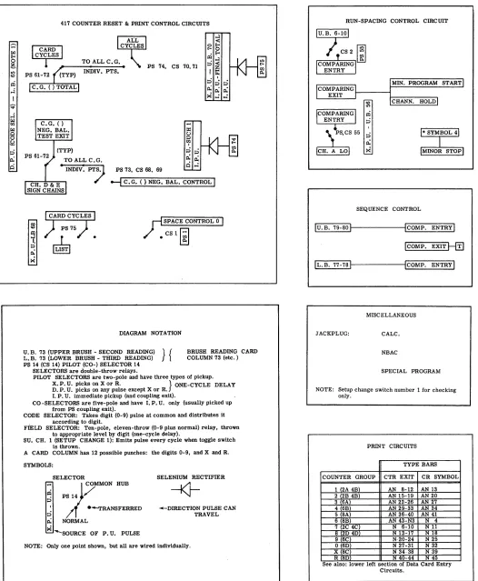
DIAGRAM NOTATION
U. B. 73 (UPPER BRUSH - SECOND READING) } { L. B. 73 (LOWER BRUSH - THIRD READING)
BRUSH. READING CARD COLUMN 73 (etc.) PS 14 (CS 14) PILOT (CO-) SELECTOR 14
SELECTORS are double-throw relays.
PILOT SELECTORS are two-pole and have three types of pickup. X. P. U. picks on X or R. } ONE-CYCLE DELAY D. P. U. picks on any pulse except X or R.
I. P. U. immediate pickup (and coupling exit).
CO -SELECTORS are five-pole and have I: P. U. only (usually picked up from PS coupling exit).
CODE SELECTOR: Takes digit (0-9) pulse at common and distributes it . according to digit.
FIELD SELECTOR: Ten-pole, eleven-throw (0-9 plus normal) relay, thrown to appropriate level by digit (one-cycle delay).
SUo CH. 1 (SETUP CHANGE 1): Emits pulse every cycle when toggle switch is thrown.
A CARD COLUMN has 12 possible punches: the digits 0-9, and X and R. SYMBOLS:
SELECTOR
~
~
PS 14P
MMONHUB : / ( ---TRANSFERRED
~ NORMAL
>< --SOURCE OF P. U. PULSE
SELENIUM RECTIFIER
--i<J----DIRECTION PULSE CAN TRAVEL
NOTE: Only one point shown, but all are wired individually.
MIN. PROGRAM START I
CHANN. HOLD I
SEQUENCE CONTROL
Iu. B. 79-S0
I
ICOMP. ENTRY IICOMP. EXIT ~
IL.B.77-7sl ICOMP. ENTRY
I
MISCELLANEOUS JACKPLUG: CALC.
NBAC
SPECIAL PROGRAM
NOTE: Setup change switch number 1 for checking only.
PRINT CIRCUITS TYPE BARS COUNTER GROUP CTR EXIT CR SYMBOL
1 2A 4B) AN S-12 AN 13 2 2B 4B) AN 15-19 AN 20 3 6A) AN 22-26 AN 27 4 6B) AN 29-33 AN 34 5 SA) AN 36-40 AN 41 6 8B) AN 43-N3 N 4 7 2C 4C) N 6-10 Nll S 2D 4D) N 13-17 NIl! 9 6C) N·20-24 N 25
o (6D) N 27-31 N 32 X (SC) N 34·38 N 39 R SD N 40-44 N 45 See also: lower left sectlOn of Data Card Entry
[image:21.612.36.562.61.700.2]Circuits.
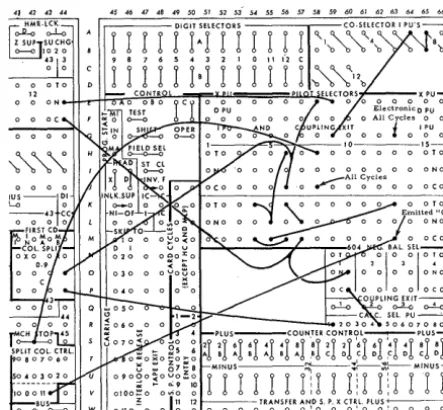
FIGURE 3B. SCHEMATIC OF TYPE 417 CONTROL PANEL WIRING DIAGRAM
S E M I N A R
only) under control of X punches over the channels A and B instruction columns. The reason for this will be discussed below. Accounting machine wiring is such that all read-in stations in the 604 reset on every card cycle if no new in-formation is entered.
Read-out from the 604 to the 417 AA or the storage regis-ter is either from the electronic counregis-ter or from general storages 2, 4, and 4-sign to the 417 AA channel C shift entry, under control of an X punch in the card column con-trolling the shift. The primary purpose of this arrangement is so that both the sine and cosine of an angle can be com-puted simultaneously in the 604, the sine being comcom-puted in general storage 4 (with sign) and the cosine in general storage 2 (always positive, as all angles are in the first or fourth quadrant). Thus, both the sine and cosine are com-puted and stored in a single storage register on one card feed. These two sources are wired into the channel C shift entry, through co-selectors, such that a column shift of five would match low-order digits at the channel C shift exit. Successive low-order digits may be dropped off (and the corresponding high-order digits picked up) by calling for shifts of 4, 3, 2, 1, or
O.
Numbers at the channelC
shift exit are available directly to anyone of the 16 storage registers under digit control from the cards to channel C control (read-in of a new number to a storage register destroys the number previously stored there). These numbers are also made available to the various counter groups through the channel Ct selector chain, along with an "add" instructionto the counter group receiving the number. As the 604 reads out true numbers plus sign, the counter reversal controls were wired to the channel C exit sign through the same chain. As shown, the field selector was used for the major portion of this chain. There are no provisions for alge-braically subtracting the results of a 604 computation from a counter group.
Provision is made for direct read-in of the test data to eight counter groups (au, tfu, nl, n2, C, Sl, S2, and r) from the key-punched data card under control of an X in card col-umn 69. Negative values are indicated by an X punched over the low-order digit of the specific number; the X picks up a pilot selector, which causes "counter minus" instead of "counter plus" to be pulsed for that counter group. The run number is printed directly from the card, and is also stored in the 604 for later transfer to a storage register. The dy-namic pressure, q, is multiplied hy the wing area,
S
w,dur-ing the data read-in cycle, and the product is stored in a storage register.
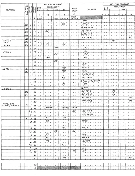
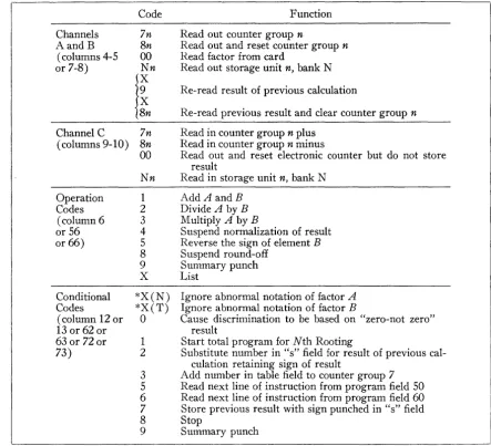
The 604 operations are as follows. The operation num-bers are those called out by card control and refer to the calculate selectors used. The detailed planning sheet for the 604 is shown in Figure 4, page 24.
23
Operation 1: sin .r, cos %
Noting that
• %3 %5
sm %
=
% -TI
+
5! - ...and
%2 %4
cos %
=
1 - 2!+
4! - . .. ,%2 %3 %4 %5 sin %
+
cos %=
1+
% - 2! - 3!+
4!+
51 - ...
00
or sin %
+
cos %=
L
Y n , n=Owhere
Yn
=
Yn-l(:;)
[f( -1)1Yo
=
1and
f ( -
1) = - 1 for a sin % term+1
for a cos % termThus, both sin % and cos ~t" may be computed
simultane-ously by alternating the sign of the multiplication and the location of the summed quantity on each sweep of the 604, continuing until Y n tests out to O. In this process, use is
made of the fact that the 604 group suppress triggers act as flip-flops; i.e., if both sides are pulsed simultaneously, the group suppress will take on the condition (on or off) oppo-site to that previously held. It should be noted that a "one" must be read into channel D (initial value of n) and "17453" into channel B (to convert degrees to radians) from the card in order to compute sin % and cos %.
Operation 2:
feNd
(see equation 3)0.0022 is read into channel A and 0.0032 into channel B. This operation discriminates on the sign of the number read into channel
E,
and uses the proper multiplying coefficient.Operation 3: BE
+
ADThis is the
F
1 of equation 7. Note that there is no roundoff, as all digits appear in the 604 counter. Unnecessary decimal places are dropped off in the channel C shift. Note also that D
+
E
may be formed by reading "ones" into channels A and B from the card, and that AD may be com-puted by leaving either B orE
blank.Operation 4: E/B (B>E/10)
This is used to compute the stability-axes coefficients. The various denominators (qS w, qS we, and qS wb) are
com-puted and stored in appropriate storage registers, available through channel B.
Operation 5: BE - AD
n
I:
i
Eli~I
""~. MULT.REMARKS OlE A """\ 8-6 B COUNTER 8-6 8-6
8f
.tz o " QUOT.,
- 2 - 3 - 4 - £ -,
- 2-
3 - 4-/ R
n,n,n!
' 10,o,/! / ,714,5.3: -:.":~;~.v, , ! , ,/ :
!
,
!
, , , ' , , ,
I
Gil I 2 i , ,;
,,
,,\0, ,-:
M::
, , , , i , :IGSI I 3
:
~ , fIz
,
I, 1 ,
, ,
,
,
, i I ,,
I4
,
,V,
RO,;
:
:
1651 / , i , , '
-,
,
IG.5J li i , 1 : : ~ /lO.J 5
,
I :
I I I , I I , : I , 1 1 : I I
IGSI I 0
,
,
I , : I i I I R I , 1 I RIr;ZI?; /
(;51 I 7,
, I I , :
I
1 I I
j
i , , I I ' I I
,
I I 'I I , 1 : I!fO
I f I I ! I :T
, 1as PU I GSI I 8 I
,
,
: I , I I I 1 I I I , I ' I ' 1I 9 ,
f~, I 1 I If!{, 1 1 I I
'~
I , ' , 1 I 1 I 1 I I I ' I I I , ,
,
, I I IEMIT
1 I 10 ~ ! I 1 \ I : , RI,
T
!
, , ' , , 1 , I
,
1 /I
I
1'{
1 I I I !I ,
I , I , :
1 , ' , , 1 I ' I I I I 1 I I I
,
,
1 1 1 1/ 12
,fP,
I Ii
I I i
, l1'f
I I I , ' i I I I :I I , I I ! I , ,
I /3
I
f<?
,!
I,
II!
1 I 1 , I I 1 I " i , 1 I I : I 1 I I : I I :
I 14
I ,
: RIC'
:
, !
:
, 1 1 I LL I 1 , I I 1 I I ,
,
, IGSPU.-i IGS2 I /5 i ,
,
, ::
I~q, ii
,fr(';L1 1 .1 i I I
:
;1 , I I I ' , I I I I I I I i
1653 I /6 I~O : I M~L, I I ' 1 I 1
I
,
, ,,
, 1 I , , 1 I 1 I ' , , , I , ,I /7
1 , , ,
y2,~D~, 1 I , 1 , , 1
i
I 1 I , I , ' 1 I I I ,
,
' , 1 , I 1 11 I I ' 1 !
I
(?/,
1!
i
, 1 , 161 , 1 I I '
, I
18 1 , , , I ! 1 : 1 , , , I
"
I I 1 I I ' , , I I ' I ' :
I /9 , I , ,
,
',
, ,
!
, I I , 0. {'"Ef~, 1 ~J ,Rf;, , , I I I 'I
,
;
,
,
, ,I , , I i
I~~
"T
,R.~ , , I :
20
,
iI '
,
1 , : I I I I I I ',
1 I ' , , : I I I ' 'as
DO.3 I 21, I
~
Il/Jf
1 1 , , 1 1 I :i
, ,
, , , ! I I I , 1 , , , ,,
, i , , I i , 1 1 1 I :it;S2 1 22
i ,
;
,
r Iff, 1 '.1 1 1 , 1 , : I~~'i
!1 I , 1 , ' I I '
,
1 , 1 1 I,
I 1IG52 I 2.~ 1 , ' I I I 1 : 1..1 I 1 i!{?,FR 12 I I I , i
, , !
, 'I : , I I ' 1i
I 24- I I '
:
, I
(i'II TO Z 1 1 I 1
:
;
,
:
I 1 1 1 , I I I I 1 I I I , I I I , I I I I
I 25 I I ' : , 1 , I I
-:
,~~ : T , , , I : , 1 : I~{' :I ' 1 I
,
1 1tt':g
2R~~ flO 2 0 / 26 1 1 ~:
,
i:
I I':
, , I
, , I I 1 , , , ' 1 , I ' , , '2 R , 1 : 1 +, F,1l~T~~
I ' ! -f~ao~,
r
nLlJE
1 I I I ' I , 1 I , : I I , , 1
24 28 I I I 1 I ' 1 i ,R~ : RI ~o,~
,
i, I
I I 1 1 , 1 1 1 , I I , I I '
2
I
I , , 1 ;
'-;- -,
~,0, I [
29 I I i 1 I , , 1 , I , ,
,
" " , , ' , , I '
+
2 .30 I 1: RI ,:
I i -I I i I ' , , '
,
I I 1 , I i
,
, , 1 I I ' , I2 31 I ,
I
,R,O, I '
I
, 1 I : M ,Y : I
i , ,
I 1 ' 1
,
,
, , I 1 I , 1 ' 1 I ' 3'2 I I i I I , I I ' , :,
I , , i,
: I I , I
I
I I :
13
5 I I :I
I~OI I I I ' , : MP, 1 ' 1 I I I '
,
II:
,3:\ I I ' I ' I I , 1 1 , 1 ' J L I I I ' '
13
5 1 I :,
1~ : I i
:
34 , , , , I
1 \ 1 I i I i " , , 1 ' 1 I I ' I , , I i
,
, I ' 1 , I , ' I , , , :3 35 ~,' I I I 1
1
;'.' I I I , , I I 11 , ,
I ' , I I , 1 1 i , I I I I I " I i
5 ~{;
;~~
I :I
1
-;
:
:, , , I : I I , 1 1 ~ 1 I I , 1 ' 1 I , I ' 1
,
I I 1 ,6 37 ,
I~~ I ' I , I
:
,~~ ~0151 I I 1 :i ,
I I 1 I I 1 I I I I I , 1 I ; I L 1 I I I
14~ 38 , 1 1 1 ;
I
IRPI I :
,
I I l J ' I ' I i i 1 i J I I I I I 1 I , I
,
,,
, , ,,
' I L' I I I I ',46 39 I I ' I , 1 I , I 1 I I I I , ' , , , 1 ,~'f
,
1 1 1 1,
::
, I I , I 1 : I I ' 'I I146 40 I
, "
,
:
I ' : 1 ' 1 ,T.Irq
1 I~~ 1 1 1 I ' I I:
1!
I I I 1 i
,
I I I 1 1 1 1 141 I , :
T
j
1 I ' , L..l ' I I i I I 1 ,
,
, : , , I,
,7 42
i ,
I~~ I : , 1 1 , :
,
, i
,R.II
I,
i 1 , , 1 , 1 ; , , 1 , , , , 1 , 1 i , 1 , 1 [image:23.620.46.563.30.705.2]1111~~::::::::::::il::l:::!I:::I::::il
FIGURE 4. TYPE 604 PLANNING CHART
S E M I N A R
25
which a choice of a particular counter group to channel D is necessary. Thus, channel D is not wired to all counter groups, but only to those requiring this operation.
are wired for conversion at print-out time. The manner in which this is accomplished is shown in Figures 3A and 3B. The only other 417 AA control of interest is the spacing control between runs. Prior to the calculation of each test point, the run number on the data card is compared to that stored from the previous point. If they are different, an automatic total cycle is initiated, which causes the tape to skip four spaces before starting the new calculation. The only purpose of this is to separate the different runs for ease in reading.
Operation 6: AjB (B>Ajl0)
This is used to compute the wind-axes coefficients, as the wind-axes airloads and moments are stored in registers and are available only to channels A and B.
Operation 7: B~ General Storage 4
This is used in the initial data read-in to hold the run number in the 604 for transfer to a storage register on the next card cycle. The denominator term, qSw, is also com-puted on this card cycle by picking up both calculate selec-tors 3 and 7 (q in A, run number in B, Sw in D, and noth-ing in E).
It should be noted that the 417 AA counters are not con-verted prior to resetting except during checking runs
(checking runs are made by listing all cycles through use of setup change switch number one). However, all counters
There is also a sequence control to stop the machine if cards in the program deck should be out of proper sequence. The wiring of this is obvious from the schematic diagram (Figure 3), and the fact that each card carries its own num-ber in columns 77-78, and the numnum-ber of the preceding card in columns 79-80. Cards are numbered from 0100 (columns 77-80) to 0041, 0100 being the data card, and the remaining 41 cards being the associated program deck.
Card-column assignments for factor read-in and the vari-ous control operations are shown in Table 1.
TABLE I
CARD COLUMN ASSIGNMENTS
Column
Numbers Item Valtte on Data Card
1-5 Channel A read-in (X-5, negative) ... Dynamic pressure, q
6-10 B (X-lO, ) ... Run number
11-15 D ... Wing area, Sw 16-20 Counter group 1 read-in (X-20, negative) ... au
21-25 2 (X-25, ) ... Y;u
26-30 3 (X-30, ) ... n1
31-35 4 (X-35, ) ... n2
36-40 5 (X-40, ) ... c
41-45 6 (X-45, ) ... Sl
46-50 7 (X-50, ) ... S2
51-55 8 (X-55, ) ... r
Column
Numbers Item Value on Program Card
1-5 Channel A read-in (X-5, negative) ... Constant
6-10 B (X-lO, ) .... ..
11-15 D ... .
56-57 A instructions ... Choose card or storage register
58-59 B ... .
60 D ... Choose card (blank) or counter 61 E ... Choose counter group
62-63 C to storage instructions ... Choose storage register 64 Ct to counter ... Choose counter group 65 Reset counter group (or groups) ... Digit to reset specified group 66 Operation ... Choose 604 operation 67 Shift ... Channel C shift control 68 Print ... X prints out counters 69 Data read-in ... X loads data in all counters 70 Clear all counter groups ... (not used)
ApPENDIX
The procedure used to design the control panel wiring described in the body of the paper may be extended to apply to any problem within the selector capacity of the machine. In a similar manner, general-purpose panels may also be built. The distinguishing feature of a general-purpose panel is that the numbers in any 417 AA counter group are avail-able, under card control, to any of the read-in stations being used in the 604. There are a variety of such panels in use at Northrop, varying in the manner in which numbers are presented to the type bars, the use of net-balance conver-sion, whether or not the 417 AA counter "read out and reset" feature (an 80 code on the CPC Model I) is wired, the manner, if any, in which numbers on cards may be read directly into 417 AA counters, and in the number of counter groups available and the number of digits in each. Use of one of these general-purpose panels, together with