doi:10.1155/2011/831724
Research Article
An Image Completion Method Using Decomposition
Bekir Dizdaro˘glu
Department of Computer Engineering, Karadeniz Technical University, 61080 Trabzon, Turkey
Correspondence should be addressed to Bekir Dizdaro˘glu,[email protected]
Received 20 July 2010; Revised 17 January 2011; Accepted 21 February 2011
Academic Editor: Douglas O’Shaughnessy
Copyright © 2011 Bekir Dizdaro˘glu. This is an open access article distributed under the Creative Commons Attribution License, which permits unrestricted use, distribution, and reproduction in any medium, provided the original work is properly cited.
This study presents a hybrid technique for simultaneously completing images by using geometry and texture components of input data. The approaches using inpainting methods based on partial differential equations (PDEs) to fill in large image regions usually fail if these regions contain textures. On the other hand, texture synthesis algorithms sometimes fail due to complex structures and textures in the image. However, this study, suggesting a hybrid method using both techniques, produces satisfactory results in completing the missing parts of images. In the proposed method, the given image is decomposed into two components. The geometry component, obtained by using the regularization PDE based on a trace operator, was inpainted by a tensor-driven PDE algorithm that takes curvatures of line integral curves into account, and the texture component, obtained by subtracting the given image from the geometry component, was reconstructed by the modified exemplar-based inpainting algorithm. Both of these methods work on color information. The main contribution of this paper is that it uses decomposition and montage stages together which provides superior results compared with the existing methods. Experimental results show that the proposed method efficiently fills in target regions, which is promising.
1. Introduction
In many cases, there might be some missing parts in images and videos, which may affect the appearance in a negative manner. Completing these missing parts properly is very important in editing images and videos for restoration (detection and removal of blotches in old motion pictures or films), correction (fixing undesirable defects such as red-eyes), manipulation (making tricky photos and creating effects on the images), and denoising.
There are two categories of image reconstruction meth-ods mentioned in the literature. These are called texture synthesis and inpainting which has received more attention in recent years. The first is generally used to reconstruct the large regions of images, and the second, PDE-based-method, is used to fill in the small image holes. Bertalmio et al. [1] presented an inpainting approach to retouch small image gaps. However, this method cannot complete large missing regions, especially including textures. Tschumperl´e
and Deriche [2] proposed the trace-based PDE method
which is not very successful because of rounding the corners
in images. Then, Tschumperl´e [3] resolved this problem
by creating an algorithm based on curvature-preserving
PDE. Criminisi et al. [4] presented an exemplar-based
image inpainting algorithm to remove large objects from images. The method fills in the missing regions by sample patches. However, sometimes artifacts are seen in the output image generated by filling in the missing parts of the
input image. Dizdaro˘glu and Gangal [5] introduced the
spatiotemporal exemplar-based image inpainting method to complete damaged regions in image sequences. But this method can also fail if it is tested on only one input image.
Bertalmio et al. [6] proposed a combined inpainting and
texture synthesis method. Since the method does not employ color information, it is sometimes unable to detect the image contours, and the filling process cannot be completed
successfully. Harald [7] introduced a combined approach
which is limited to the removal of small image holes, while
continuing to blur the completed region. Sun et al. [8]
presented an image repairing method that needs the users’ guidance to propagate the structure in the filled region.
Drori et al. [9] obtained the best fragments to retouch
Image contour
Figure1:ηandθ−vectors at pointp.
consuming. Jia and Tang [10] used a tensor voting method to fill in the degraded regions of the image which also utilize image segmentation. However, current algorithms are not able to segment images completely. Komodakis and Tziritas
[11] proposed a method to complete missing regions by
employing priority-belief propagation algorithm. But this approach is very slow in inpainting large missing regions. Although Wexler et al. [12] suggests a solution based on pattern similarity to fill in target regions, it is also proven to be too slow. Dizdaro˘glu [13] presented another method that reconstructs the completed region by employing both the geometry and texture information of the input image, on which this paper is structured. The method is able to generate plausible results. Fadili and Starck [14] employed the expectation maximization method to inpaint missing regions. But the method may be unsatisfactory because it generates blurring effects in inpainting large missing regions. Liu et al. [15] used an image completion method based on views of large displacement. However, it requires tiresome interactive segmentation. Barnes et al. [16] proposed image editing tools employing a randomized algorithm for quickly finding the best match between image patches, that is, for the purpose of completing image regions. But this application does not work automatically but interactively. Ign´acio and Jung [17] introduced another method that is also computationally complex in block-based image inpainting in the wavelet domain. Xu and Sun [18] suggested an exemplar-based inpainting method using patch propagation exemplar-based on patch selection and patch inpainting. However, the results of this method show that sometimes the edges are not connected properly in the filled regions.
Since the previous methods generate unsatisfactory re-sults in some cases we presented an approach that is capable of processing both geometry and texture images simultane-ously in order to obtain the visually plausible reconstructed image.
2. The Proposed Method
The proposed method contains image decomposition, inpainting and texture synthesis.
LetI:Ω → Rnbe a multivalued (color) image (n=3),
defined on domainΩ → R2, andI
i:Ω → Rrepresents the image channeliofI(1≤i≤n): for allp∈Ω. The method is explained in detail in the following sections.
Figure2: Gradient norm of Barbara color image.
Figure3: Tensor directions of Barbara image.
2.1. Image Decomposition. In the equationI= Iu+Iv, which
shows the entire image, Iu and Iv represent the geometry
image and the texture image, respectively. According to
the equation, it can be seen that the texture image Iv is
generated by subtractingIufromI. Texture information can be considered as a kind of noise while geometry information can be considered as a cartoon version with sharp edges. Meyer [20] first introduced a space of oscillating function to model the texture component of an image. Vese and Osher
[21] presented a decomposition approach employing the
total variation minimization for image denoising [22], and then this method was adapted for the simultaneous texture
and geometry image inpainting [6]. A simple and rapid
version of Meyer’s model was presented for decomposition
which is seen a new nonlinear filter [19]. However, a
denoising algorithm based on PDE can be used in order to obtain geometry image. In this study, the trace-based-method [2] is preferred among those algorithms.
Denoising or regularization of a scalar imageI : Ω →
R based on PDEs is a smoothing operation along the
(a) (b)
(c) (d)
(e) (f)
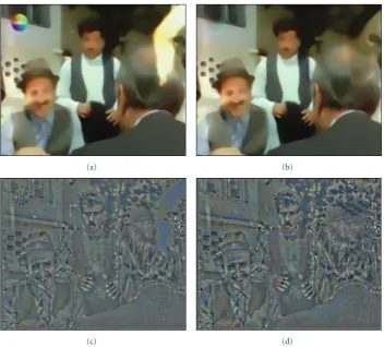
Figure4: Chosen parts of decomposed components of the input image and the output images: the geometry images (a) and (b) and the tex-ture images (c) and (d), and the output images (e) and (f) are obtained by the method in [19] (left side) and the proposed method (right side).
the region. Here, the smoothing operation should not blur the edges, which could be ensured by avoiding smoothing orthogonally to edges. In order to do this, the local geometry of image should be obtained in the first place.
The following conditions consisting of important
fea-tures are provided in every image point p = (x,y) ∈ Ω
[2,3].
(i) Two orthogonal directions θ+(p),θ−(p) ∈ S1 (unit
vectors ofR2) determined by maximum and
mini-mum intensity variations at the pointpare defined to show the gradient vector, and the edge if there is any, respectively.
(ii) The positive valuesλ+(p), λ−(p) are calculated
relat-ed to clarity of the relat-edges to show effective variations of the image intensities alongθ+(p) andθ−(p).
The local geometry {λ+/−,θ+/− | p ∈ Ω} of scalar
images I is calculated based on the gradient field ∇I
or the smoothed gradient field ∇Iσ = Gσ ∗∇I. Here,
Gσ =(1/2πσ2) exp(−(x2+y2)/2σ2) is a 2-dimensional (2D) Gaussian kernel with a varianceσ.
The image gradient is the derivation of ascalar imageI
related to the spatial coordinatesp:
∇I=Ix,Iy
T =
∂I ∂x,
∂I ∂y
T
. (1)
A vector∇I : Ω → R2 is created according to the image
gradient to represent magnitudes of the scalar imageI and the maximum variation directions. Scalar and pointwise
measure of the image variations are given by the gradient
norm∇Iwhich is used in image analysis in many cases:
∇I = ∂I
∂x 2
+
∂I ∂y
2
. (2)
Therefore, λ+ = ∇I2 and θ− = η⊥ = ∇⊥I/∇I are
possible measures of the intensity and direction of the image edge, respectively, (seeFigure 1).
Here,G:Ω → P(2) of 2×2 symmetric and semipositive tensors, denoted by for all p ∈ Ω, G(p) = λ−θ−θ−T +
λ+θ+θ+T
(a) (b)
(c) (d)
Figure5: Closeups of decomposed components of the input image: the geometry images (a) and (b) and the texture images (c) and (d) are obtained by the method in [6] (left side) and the proposed method (right side).
The local geometry for multivalued images I can be
obtained in a similar way, by computing the field Gof
geometry tensors. Therefore, the gradient of multivalued images is expressed as follows:
∀p∈Ω, Gp= n
i=1
∇Ii∇IiT, where∇Ii= ⎛ ⎜ ⎜ ⎜ ⎝
∂Ii ∂x ∂Ii ∂y
⎞ ⎟ ⎟ ⎟ ⎠.
(3) Gis defined as the following for color imagesI=(R,G,B):
G=
⎛ ⎝g11 g12
g21 g22
⎞ ⎠
= ⎛
⎝ R2x+G2x+B2x RxRy+GxGy+BxBy RyRx+GyGx+ByBx R2y+G2y+B2y
⎞ ⎠.
(4)
The positive eigenvaluesλ+/− and the orthogonal
eigenvec-torsθ+/−ofGare formulized as follows:
λ+/−=
g11+g22±
g11−g22
2 + 4g122
2 ,
θ+/−=
⎛ ⎜ ⎝
2g12
g22−g11±
g11−g22
2 + 4g122
⎞ ⎟ ⎠.
(5)
The gradient norm ∇I of color image is easy to compute as follows since it perceives image structures successfully (seeFigure 2):
∇I =λ++λ−=
n
i=1
a <0
a=0
a >0
p
w(Cp(a))
Figure6: Integral curveCp(a) of vector fieldsw:Ω→ R2.
Figure7: A chosen part of the inpainted geometry image.
More consistent geometry is obtained provided that
Gσ = G∗Gσ is smoothed by the Gaussian filter. Here,Gσ
is a good estimator of the local multivalued geometry ofIat the pointp, and its spectral elements give the vector-valued variations (by the eigenvaluesλ−,λ+ ofGσ) at the same time and the orientations (edges) of the local image structures (by the eigenvectorsθ−⊥θ+ofGσ).
Tschumperl´e and Deriche [2] suggested designing a
particular fieldT : Ω → P(2) ofdiffusion tensorsto define the specification of the local smoothing method for the regularization process. Apparently, it should be noticed that Tdepending on the local geometry ofIis thus defined from the spectral elementsλ+,λ−andθ+,θ−ofGσ:
∀p∈Ω, Tp= f−λ+,λ−θ−θ−T
+ f+λ+,λ−θ+θ+T. (7)
The strengths of smoothing along θ−,θ+ are set by two
functions denoted by f−/+ : R2 → R, where the types
of applications determine f− and f+. Sample functions for image denoising are proposed in [2]:
f−λ+,λ−= 1
1 +λ++λ−p1 ,
f+λ+,λ−= 1
1 +λ++λ−p2
, withp1<p2.
(8)
Here, the goal of smoothing operation is as follows.
(i) The pixels on image edges are smoothed along θ−
with a strength inversely relative to the vector edge strength (anisotropic smoothing).
(ii) The pixels on homogeneous regions are smoothed along all possible directions (isotropic smoothing).
Φi
δ훤i
훤i
p q
Ψq
i Ψpi
Figure8: The modified exemplar-based inpainting diagram.
Figure9: A chosen part of the completed texture image.
The tensor directions for Barbara color image are depicted inFigure 3.
Tschumperl´e and Deriche [2] suggests a regularization-PDE-based approach to agree with the local smoothing geometryTbased on atraceoperator:
∂I ∂t =
∂Ii
∂t =trace(THi), (9)
whereHiis the Hessian matrix ofIi:
Hi= ⎛ ⎜ ⎜ ⎜ ⎜ ⎜ ⎝
∂2Ii ∂x2
∂2Ii ∂x∂y
∂2Ii ∂y∂x
∂2Ii ∂y2 ⎞ ⎟ ⎟ ⎟ ⎟ ⎟
⎠. (10)
In this study,Hiis asymmetric matrixsince the images are regular ones,∂2Ii/∂x∂y=∂2Ii/∂y∂x.
As Tschumperl´e and Deriche [2] have shown, equation (9) can be viewed as a local filtering with oriented and normalized Gaussian kernels. Here, a small convolution is locally applied around each pointpwith a 2D Gaussian mask
GTt orientedby the tensorT(p):
GTt
p= 1
4πtexp
−pTT−1p 4t
. (11)
As a matter of fact, a link exists between anisotropic diffusion PDE and classical filtering techniques:
∂Ii
∂t =trace(THi)⇐⇒∂Ii(t)=Ii(t=0)∗G T
(a) (b)
(c) (d)
(e) (f)
Figure10: An input image for object removal (a), the mask image (b), the method in [7] (c), the exemplar-based inpainting method [4] (d), the modified exemplar-based inpainting method (e), and the proposed method (f).
The regularization PDE shown in the following equation is compatible with all local geometric properties expressed before:
I(t=0)=Iinitial,
I(t+1)=I(t)+dt ∂I(t)
∂t ,
(13)
wheredtstands for adapting time step.
The suggested technique for image decomposition is used
to generate the image geometry. Results given in Figure 4
are obtained using decomposition and montage algorithms. Unlike the method presented in [19], the proposed method assembles the texture and geometry components successfully and generate the output image almost the same as the input, which is shown in the figure.
Figure 5illustrates another result obtained by using the decomposition algorithms. We compare our method with
the method presented in [6] after converting decomposed
components of the test image to grayscale since [6] also employs a grayscale version of the image. There is less texture
information in our geometry component and our texture component is also appreciably sharper than the method in [6], as shown in the figure. Besides, if the number of iteration is increased more, the geometry component is better smoothed, which results less texture information to remain in the geometry component.
2.2. Inpainting. The trace-based-method behaves locally as an oriented Gaussian smoothing filter. The strength and orientation of this smoothing filter is directly related with
the tensor T. This method preserves edges; but, it tends
to cause unacceptable rounding effects oncurvedstructures such as corners. It is because the 2D Gaussian kernel does not consider curvatures. For this reason, Tschumperl´e proposed
another technique [3] which can be considered filtering
(a) (b)
(c) (d)
Figure11: A test image for completing artificially degraded regions (a), the constrained PDE-based-method [3] (b), the modified exemplar-based inpainting method (c), and the proposed method (d).
This new technique, thecurvature-preserving regulariza-tion PDE[3],which smoothesIalong a vector fieldw:Ω → R2instead of a tensor fieldT, is defined as follows:
∂Ii ∂t =trace
wwTHi+∇IT
i Jww, (14)
whereJwdenotes the Jacobian ofw:
Jw=
⎛ ⎜ ⎜ ⎜ ⎝
∂u ∂x
∂u ∂y ∂v ∂x
∂v ∂y
⎞ ⎟ ⎟ ⎟
⎠. (15)
The added term∇IiTJwwnaturally depends on the variation
of the vector field w. By means of this term, the given
image is smoothed along a single direction w/w, with
a smoothing strength of w. There are the two spatial
components ofw(p)= (u(p),v(p))T. This approach can be briefly explained as follows.
Suppose thatCp(a) is the curve defining theintegral curve
of w, starting from p and parameterized by a ∈ R (see
Figure 6):
Cp(0)=p,
∂Cp(a) ∂a =w(C
p(a)). (16)
Whena → +∞, the integral curveCp(a) is tracked forward,
and whena → −∞it is tracked backward.
The second derivative of the functiona → Ii(Cp(a)) at a=0 is obtained by using Taylor’s formula as follows:
∂Ii(Cp(a)) ∂t =
∂2Ii(Cp(a)) ∂a2
=tracewpwpTHip+∇IT iJw
pwp.
(a) (b)
(c) (d)
Figure12: A given image for object removal (a), the mask image (b), the method in [8] (c), and the proposed method (d).
(a) (b)
(c) (d)
(a) (b)
(c) (d)
Figure14: A given image for large object removal (a), the mask image (b), the exemplar-based inpainting method [4] (c), and the proposed method (d).
To regularize multivalued images, Tschumperl´e [3] ex-tended the single-direction smoothing PDE (14) so that it can deal with tensor-valued geometryT:Ω → P(2), instead of a vector-valued geometrywby writingTas
T= 2
π π
α=0
TaαTaαTdα, (18)
whereaα=(cosα sinα)T and √
T=f−uuT+f+vvT is
the square root ofT. (√T)2 = Tand (√T)T = √Tcan be
easily verified. Then, the PDE (14) is solved by Tschumperl´e [3] as follows:
∂Ii
∂t =trace(THi) +
2
π∇I T i
π
α=0 J√Taα
Taαdα, (19)
where J√Taα stands for the Jacobian of Ω →√Taα. A
practical approach for this solution can be expressed as in:
I[t+dt]= 1 N
N−1
k=0 I[LICt](√
(a) (b)
(c) (d) (e)
Figure15: A given image for completing an artificially degraded region (a), the mask image with the user’s guidance (b), close-ups of the method in [16] (c), the method employing the user’s guidance in [16] (d), and the proposed method (e).
where each Gaussian variance has a standard deviation dt, andI[LICt](·) stands for the line integral convolution. The most
difficult operation here is the LIC computation, which
requires the tracking of integral curves of a vector field. In order to solve this problem, a very simple technique based on the classical Runge-Kutta integration scheme is employed by Tschumperl´e [3]. Although another faster LIC computation has developed in [23], it does not utilize Gaussian weighting functions, as needed here:
I[LICt]
p=
+∞
−∞I
[t=0](Cp(x))G
t(x)dx, (21)
whereGt(x) stands for 1D Gaussian kernel function as shown in:
Gt(x)= 1
√
4πtexp
−x2 4t
. (22)
The outlines of the implementation of suggested algo-rithm for a single iteration are as follows.
(1) The smoothed geometry fieldGσ is computed from
I[t].
(2) The eigenvalues and eigenvectors of Gσ are
com-puted.
(3) The diffusion tensor fieldTis computed fromGσ. (4) Forαin all [0,π]:
(i) the vector fieldw=√Taαis computed, (ii) LIC operation ofI[t]is applied in forward and
backward directions alongCp.
(5) The average of all LICs is computed in step (4). The result of the inpainting algorithm on the geometry image is depicted inFigure 7.
(a) (b)
(c) (d)
Figure16: A given image for removal of artificially added scratches (a), the mask image (b) the method in [18] (c), and the proposed method (d).
obtaining the data term and attempting to find the best sample patch in the search region.
The method represented in Figure 8 requires a clarifi-cation. In the drawing, I(p) is a pixel value in the input image,Γiis the region that needs some reconstruction,δΓiis boundary ofΓi, andΦiis the search region that is composed of sample patches.Ψpi is the actual patch that is to be filled at the pointponδΓi. The filling priority of boundary points on the target area is found as follows:
ρp=γpDp,
γp=1 n
n
i=1
γi
p,
γi
p=
q∈Ψp
i∩Φi γi
q
AreaΨpi,
Dp= 1
n n
i=1
Di
p,
Di
p=|trace(THi)|
255 ,
(23)
whereγi(p) shows the confidence term indicating the filling priority from the outer layers of the target region towards inner layers, and Di(p), modified to take into account multivalued images, is the term giving the priority based on the gradient values such as edge information. Area(Ψpi) is the area ofΨpi andTstands forf−(λ+,λ−)θ−θ−T.
γi(p) is set to following values during the initialization:
γi
p=
⎧ ⎨ ⎩
1, ∀p∈Φi,
0, ∀p∈Γi. (24)
(a) (b)
(c) (d)
(e) (f)
Figure17: The input images (a) and (b) for image completion, the mask images (c) and (d) and output images (e) and (f) are generated by the proposed method.
the algorithm compared with the techniques considering the whole image instead of the search region only. Here, after finding maximum priority patchΨpi, the best model patch is investigated within the search regions, where distanced= n
i=1di(Ψpi,Ψ
q
i) between the patchesΨ
p i andΨ
q
i is calculated as the WSSD of pixels that have already been filled. The best sample patch is copied from the search region to the target region. The confidence values are updated in every step.
Figure 9shows the result of texture synthesis operation suggested in the study on the texture image.
3. Experimental Results
The proposed method is tested on several color images, some of which are taken from other studies in the literature in order to make a comparison. In the modified exemplar-based inpainting method, ranges of the search regions are chosen between 30 and 70 pixels. Other parameters are kept the same as in the referenced papers. We also apply a dilation operation on the mask images to obtain the better results.
(a) (b)
(c) (d)
Figure18: Geometry (a) and texture (c) components are generated by the proposed method, and the reconstructed geometry image (b) and the completed texture image (d) are obtained by the proposed method.
in Figure 10. Figures 10(c) and 10(d) shows the result of methods proposed in [7] and [4], respectively. Unlike these methods, our modified exemplar-based inpainting method produces an almost perfect result on the brick wall and trees as seen inFigure 10(e). Actually, there is no need to apply another proposed method based on the summation of geom-etry and texture components if the given image does not con-tain complex structure and texture information. As an exam-ple, we still give another result generated by the combined approach in Figure 10(f), where image structure is propa-gated better than the modified exemplar-based-method.
Figure 11 demonstrates the results of the constrained
PDE-based inpainting method [3], the modified
exemplar-based inpainting method and the proposed method on Barbara image, respectively. As seen in these results, the proposed method gives the best visual quality compared with the others; but, there is color scattering on some of the completed parts, especially on the transitional region between arm and knee.
Figure 12 compares the proposed method with the
approach presented in [8]. Figure 12(d) shows that the
structure is completed in the target region using our method successfully. The method in [8] necessitates a guided structure propagation process, where the user draws curves to join the image geometry properly in the filling regions. Unlike that, our method works completely automatic.
Figure 13 illustrates another comparison between the proposed and other methods in terms of successes in repairing the artificially degraded regions. The method in
[17] completes the target area better than the proposed
method. But the proposed method has less computational complexity than the method presented in [17], which uses the wavelet domain and extra information in order to find the best patch to match and synthesis.
Figure 14 depicts removal of a large object from a photograph. The structure is obtained by the proposed
method better than the method in [4]; however, texture
information in some of the completed region cannot be estimated, especially in the roof.
Figure 15demonstrates another example of completion
of the region having complex textures.Figure 15(c) shows
the result of the method presented in [16] using only a
mask image, which does not generate efficient results on
the wall and the tree pictures. Figure 15(d) presents the
completed result, where the user’s guidance is used. Our method seems to generate promising results whereas it produces blurring effects in some filling regions as shown in
Figure 15(e).
Figure 16 depicts an example of scratch removal. The method in [18] does not propagate the structure as seen in
2005 by taking advantage ofCImg library[24]. The program was run on a PC with Pentium 2.20 GHz processor and 2 GB RAM. The runtime of the proposed method is changing depending on size of filling regions. The process for the
degraded Barbara image of size 512 × 512 presented in
Figure 11(d)takes about 4 minutes.
4. Conclusion
This study proposes a method that combines the advan-tages of inpainting and texture synthesis approaches. Both approaches are separately applied to decomposed images. Results of both approaches are then combined to reconstruct the output image. The result shows that the output image is of acceptable quality.
As a future task automatic search capability could be developed for search regions in the modified exemplar-based inpainting method since the dimension of the search region is manually arranged at present. The proposed method also generates color scattering and blurring effects on some of the filling regions. These drawbacks can also be eliminated in another future task.
We conduct research on the current modified exemplar-based inpainting algorithm to restore old motion picture films by extending the spatiotemporal domain. Actually, there is no need to apply the proposed method, based on decomposition, on the film frames, because adequate information to fill in the degraded region of the current frame could be found in the previous and next frames. So blotches are easily concealed by using the modified exemplar-based-method because they do not appear in the same spatial locations in successive frames, and the computational complexity can be reduced as well.
References
[1] M. Bertalmio, G. Sapiro, V. Caselles, and C. Ballester, “Image inpainting,” inProceedings of ACM SIGGRAPH, pp. 417–424, New Orleans, La, USA, 2000.
[2] D. Tschumperl´e and R. Deriche, “Vector-valued image reg-ularization with PDEs: a common framework for different applications,” IEEE Transactions on Pattern Analysis and Machine Intelligence, vol. 27, no. 4, pp. 506–517, 2005. [3] D. Tschumperl´e, “Fast anisotropic smoothing of multi-valued
images using curvature-preserving PDE’s,”International Jour-nal of Computer Vision, vol. 68, no. 1, pp. 65–82, 2006. [4] A. Criminisi, P. P´erez, and K. Toyama, “Region filling and
object removal by exemplar-based image inpainting,” IEEE Transactions on Image Processing, vol. 13, no. 9, pp. 1200–1212, 2004.
to inpainting,” inProceedings of the ECCV, vol. 2, pp. 214–224, 2004.
[8] J. Sun, L. Yuan, J. Jia, and H. Y. Shum, “Image completion with structure propagation,” inProceedings of the ACM SIGGRAPH, pp. 861–868, August 2005.
[9] I. Drori, D. Cohen-Or, and H. Yeshurun, “Fragment-based image completion,” inProceedings of the ACM SIGGRAPH, pp. 303–312, July 2003.
[10] J. Jia and C. K. Tang, “Image repairing: robust image synthesis by adaptive ND tensor voting,” inProceedings of the IEEE Computer Society Conference on Computer Vision and Pattern Recognition, pp. 643–650, June 2003.
[11] N. Komodakis and G. Tziritas, “Image completion using effi -cient belief propagation via priority scheduling and dynamic pruning,” IEEE Transactions on Image Processing, vol. 16, no. 11, pp. 2649–2661, 2007.
[12] Y. Wexler, E. Shechtman, and M. Irani, “Space-time video completion,” in Proceedings of the IEEE Computer Society Conference on Computer Vision and Pattern Recognition (CVPR ’04), pp. 120–127, July 2004.
[13] B. Dizdaro˘glu, “Color image completion using simultaneous geometry and texture,” inProceedings of the 13th World Multi-Conference on Systemics, Cybernetics and Informatics, Orlando, Fla, USA, July 2009.
[14] M. J. Fadili and J. L. Starck, “EM algorithm for sparse representation-based image inpainting,” inProceedings of the IEEE International Conference on Image Processing (ICIP ’05), pp. 61–64, September 2005.
[15] C. Liu, Y. Guo, L. Pan, Q. Peng, and F. Zhang, “Image completion based on views of large displacement,” Visual Computer, vol. 23, no. 9–11, pp. 833–841, 2007.
[16] C. Barnes, E. Shechtman, A. Finkelstein, and D. B. Goldman, “PatchMatch: a randomized correspondence algorithm for structural image editing,” inProceedings of the ACM Transac-tions on Graphics (SIGGRAPH ’09), vol. 28, no. 3, July 2009. [17] U. A. Ign´acio and C. R. Jung, “Block-based image inpainting
in the wavelet domain,”Visual Computer, vol. 23, no. 9-11, pp. 733–741, 2007.
[18] Z. Xu and J. Sun, “Image inpainting by patch propagation using patch sparsity,”IEEE Transactions on Image Processing, vol. 19, no. 5, pp. 1153–1165, 2010.
[19] A. Buades, T. M. Le, J.-M. Morel, and L. A. Vese, “Fast cartoon + texture image filters,”IEEE Transactions on Image Processing, vol. 19, no. 8, pp. 1978–1986, 2010.
[20] Y. Meyer, “Oscillating patterns in image processing and nonlinear evolution equations: the fifteenth Dean Jacqueline B. Lewis memorial lectures,”American Mathematical Society, 2001.
[22] L. A. Vese and S. J. Osher, “Image denoising and decom-position with total variation minimization and oscillatory functions,” Journal of Mathematical Imaging and Vision, vol. 20, no. 1-2, pp. 7–18, 2004.
[23] D. Stalling and H. C. Hege, “Fast and resolution independent line integral convolution,” inProceedings of the 22nd Annual ACM Conference on Computer Graphics and Interactive Tech-niques, pp. 249–256, August 1995.
![Figure 10: An input image for object removal (a), the mask image (b), the method in [7] (c), the exemplar-based inpainting method [4](d), the modified exemplar-based inpainting method (e), and the proposed method (f).](https://thumb-us.123doks.com/thumbv2/123dok_us/1147224.1143981/6.600.124.477.72.455/figure-removal-exemplar-inpainting-modied-exemplar-inpainting-proposed.webp)
![Figure 11: A test image for completing artificially degraded regions (a), the constrained PDE-based-method [3] (b), the modified exemplar-based inpainting method (c), and the proposed method (d).](https://thumb-us.123doks.com/thumbv2/123dok_us/1147224.1143981/7.600.124.476.74.459/completing-articially-degraded-constrained-modied-exemplar-inpainting-proposed.webp)