c
(
( \
[TELEVIDEO(l)
90S VIDEO DISPLAY TERMINAL OPERATOR'S MANUAL
Tele Video Document 131975-00-B 1 June 1986
Copyright
Copyright (c) 1986 by TeleVideo Systems, Inc. All rights reserved. No part of this publication may be reproduced, transmitted, transcribed, stored in a retrieval system, or translated into any language or computer language, in any form or by any means, electronic, mechanical, magnetic, optical, chemical, manual, or otherwise, without the prior written permISSIon of TeleVideo Systems, Inc., 1170 Morse A venue, P.O. Box 3568, Sunnyvale, CA 94088-3568.
Disclaimer
TeleVideo Systems, Inc. makes no representations or warranties with
respect to this manual. Furt~er, TeleVideo Systems, Inc. reserves
the right to make changes in. the specifications of the product described within this manual at any time without notice and without obligation of TeleVideo Systems, Inc. to notify any person of such revision or changes.
TeleVideo is a registered trademark of TeleVideo Systems, Inc. WordStarT.M·is a trademark of MicroPro International Corp., Inc.
ADDS~ Viewpoint(l) and Regent(l) are registered trademarks of Applied Digital Data Systems, Inc.
ADM 3A/5 T.M. is a trademark of Lear Siegler, Inc. Hazeltine T.M. is a trademark of Hazeltine Corp.
Qume T.M. and QVT T.M. are trademarks of Qume Corporation.
FCC Class A Warning
This peripheral equipment generates, uses, and can radiate radio frequency energy. If not installed and used in accordance with the instruction manual, it may caus(: interference with radio emissions. This peripheral equipment has been tested and found to comply with
the limits for a Class A computing device, pursuant to Subpart J of
Part 15 of FCC Rules, which are designed to provide reasonable protection against radio frequency interference when operated in a
commercial environment. Operation of this equipment in a
residential area is likely to cause interference, in which case the user at his own risk and expense will be required to correct the interference. The use of nonshielded I/O cables may not guarantee compliance with FCC RFI limits.
T ABLE OF CONTENTS
INTRODUCTION
Meet the 905 Terminal
Using This Manual Attention, Please
Ordering Other Publications
Manual Order Form
1. INST ALLA TION
xi
xii xii xiii
xv
Installation Steps 1.1
Obtaining the Interface Cables 1.1
Unpacking the 905 1.2
Checking Voltage Setting 1.3
Placing the Terminal in a Suitable Location 1.4
Attaching the Keyboard 1.5
Connecting the 905 to a Computer 1.6
Connecting Your Printer to the 905 1.7
Plugging in the 905 1.8
Turning On the Power 1.9
Adjusting the Screen and Keyboard 1.9
The Next Step 1.10
2. SET UP
Review of the Set Up Process Entering Set Up
Selecting a Set Up Menu Selecting a Set Up Field
Changing the Set Up Parameter Value Leaving Set Up
Setting Up the 905 Main Menu Print Menu Keyboard Menu Screen Menu
Miscellaneous Menu
Reprogramming the Function Keys Second Miscellaneous Menu
Reprogramming the Answerback Message
3. OPERATING THE 90S
The Keyboard
Alphanumeric Keypad The Numeric Keypad The Editing Keypad The Function Key Row
Editing and Sending Data
Communication and Editing Key Modes Sending Data to the Computer
Printing
Resetting the Terminal
Screen Appearance The Cursor Screen Saver The Status Line
Contents Iv
4. MAINTENANCE AND ASSISTANCE
Trou bleshooting·
Running the Self Test
Checking and Replacing the Line Fuse
If You Need Assistance Service Under Warranty Shipping the Terminal
S. PROGRAMMING THE 90S
Entering Commands
Sending Commands From the Host Entering Commands From the Keyboard Command Format
Verifying Operations Self Test
Monitor Mode
Resetting the Terminal
Keyboard and Bell
Locking/Unlocking the Keyboard Edi ting Key Mode
Keyclick
Sounding the Bell
Screen Appearance Screen Visibility Screen Background Cursor Style
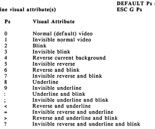
Visual Attributes Special Graphics Mode
Editing Modes
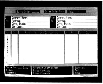
Write Protect and Protect Modes Creating a Protected Form Au toscroll Mode
Contents v
Cursor Control
Line Feed and Reverse Line Feed Cursor Movement
Addressing the Cursor Reading the Cursor Cursor Home
Tab Stops
Setting Tab Stops Clearing Tab Stop(s)
Moving the Cursor to a Tab Stop
Editing Data
Inserting Data Deleting Data Erasing Data Clearing Data
Communicating With the Computer Selecting a Handshaking Protocol Communication Modes
Setting the Communication Mode
Sending Screen Data in Block Mode Delimiters
Reprogramming Delimiters Text Markers
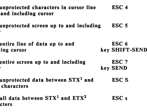
Sending Data
Loading and Sending Messages Displaying the Message Line Loading the Message Line
The Default Function Key Codes Reprogramming Function Keys The FUNCT Key
Sending the Terminal Identification Sending the Answerback Message
Printing
Print Modes and Protocols Print Commands
Page Print Terminator
Contents vi
APPENDICES
A Specifications
B Statement of Limited Warranty
C ASCII Tables
D RS-232C Signal Assignments
E Cursor Coordinates
F Key Descriptions
G Control Codes and Escape Sequences
H WordStar Commands
I Calcula tor Mode
J Status Line Messages
K Foreign Character Sets
GLOSSARY
INDEX
QUICK REFERENCE GUIDE
LIST OF TABLES 2-1 2-2 2-3
2-4
2-5. 2-6 4-1 5-15-2
5-35-4
5-5 5-6 5-7 5-8 5-9 5-10 5-11 5-12 5-13 5-14 C-I C-2 C-3 0-1 0-2 0-3 F-l G-I K-IMain Port Parameters Printer Port Parameters Keyboard Parameters Screen Parameters
Miscellaneous Parameters Miscellaneous 2 Parameters
Troubleshooting Terminal Problems Summary of Reset Methods
Effects of Visual Attributes Effects of Protect Mode
Causes of Data Loss in Autoscroll Mode
Cursor Movement After a Line Feed Command Cursor Movement After a Reverse Line
Feed Command
Effect of the Cursor Right Command
Effect of Protect Mode on Tabulation Commands Effect of Protect Mode on Insert Commands Eff ect of Protect Mode on Delete Commands Communication Modes
Default Delimiter Values Send Commands
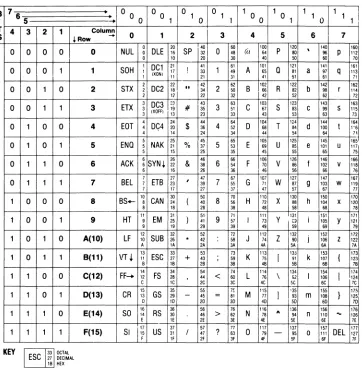
Default Function Key Codes ASCII Code Chart
Monitor Mode Control Characters ASCII Control Character Abbriviations Main Port (DTE) Signal Assignments Printer Port (DCE) Signal Assignments Commonly Required RS-232C Signals Key Functions
Command Set Summary Character Set Comparison
Contents viii
LIST OF FIGURES 1-1 1-2 1-3 1-4 1-5 1-6 1-7 1-8 1-9 2-1 2-2 2-3 2-4 2-5 2-6 2-7 2-8 2-9 2-10 2-11 3-1 3-2 3-3 3-4 4-1 4-2 5-1 5-2 5-3 5-4 5-5 5-6 5-7 5-8 5-9
Terminal Components Voltage Label
Proper Terminal Placement Plugging In the Keyboard Computer Interface Printer Interface Plugging In the 905 Turning On the Power Adjusting the Terminal The SET UP Key
Selecting a Set Up Menu Moving to a Set Up Field Changing a Value
Saving Set Up Values The Main Port Menu Printer Port Menu Keyboard Menu Screen Menu
The Miscellaneous Menu Second Miscellaneous Menu The 905 Keyboard
How the SEND Key Works How the PRINT Key Works The 905 Status Line
The Self Test Screen The Line Fuse
Typical Monitor Mode Display Special Graphics Characters
Sample Form With Protected Headings Data Loss During Scrolling
Setting Field Tab Stops Deleting Data
Erasing Data
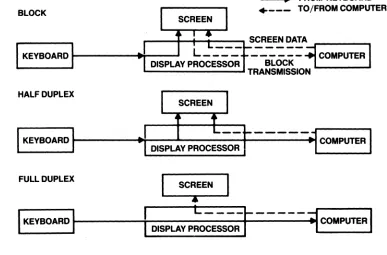
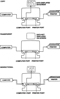
Data Flow in Communication Modes Print Modes
Contents Ix
LIST OF FIGURES (continued)
D-l 2S-Pin RS-232C Connector
F-l Keys Affected by Editing Key Mode F-2 Other Editing Keys
F-3 Special and Local Keys F-4 Alphanumeric Keys
K-l U.S. ASCII Keyboard Layout K-2 U.K. Keyboard Layout K-3 German Keyboard Layout K-4 French Keyboard Layout
K-S Spanish Keyboard Layout
K-6 Norwegian Keyboard Layout K-7 Finnish Keyboard Layout . K-8 Italian Keyboard Layout
Contents x
D.3 F.l F.l F.2 F.2 K.2 K.2 K.3 K.3 K.4 K.4
INTRODUCTION
MEET THE 90S TERMINAL
The 905 terminal is the low-cost. high-quality member of the
TeleVideo ASCII terminal family. It is compatible with the
TeleVideo 925 and 910 terminals. as well as ADDS Viewpoint A2. ADDS Regent 25. ADM 3A/5. Hazeltine 1410/1500. and Qume QVT
101 codes. It also features an operator-selectable WordStar mode
that changes the editing and function key codes to the most-used WordStar commands.
The 905 offers a 14-inch. high-resolution screen; tilt-and swivel case; 25th status/message line; 32 function keys (16 programmable); and an accounting-style numeric keypad.
USING THIS MANUAL
Chapter 1 contains step-by-step instructions showing how to install the terminal.
Chapter 2 tells how to set the terminal's operating characteristics and configure it to communicate with your computer and printer.
Chapter 3 describes the keys and terminal operations controlled from the keyboard.
Chapter 4 has a troubleshooting table and tells how to get assistance if you have questions or problems.
Chapters S is for programmers. It explains how the terminal operates and all the programming commands.
Reference material is found at the back of the manual: appendices, glossary, index, and a programmer's quick reference guide.
Attention; Please
This manual has three types of notices you should read carefully:
NOTE: Information of special interest or importance about a feature.
WARNING! This procedure might destroy data or damage equipment. Make sure you read and understand thoroughly what you are doing before proceeding.
STOP! This procedure might cause you physical harm. Stop what you're doing and read instructions carefully before proceeding. Call a service technician, if necessary.
Ordering Other Publications
TeleVideo offers a maintenance manual for the 905 (PN 131978-00) and a free booklet showing how to incorporate terminal programming
commands in a program written in BASIC (PN 113000-80). The
maintenance manual is $50.
To order the free programming booklet, check the box on the reader comment card included with this manual and mail it postage-free (in
the USA) to TeleVideo. Mailing the card from outside the USA
requires proper postage. Or contact TeleVideo at the phone numbers listed below and ask for the Literature Department.
To order the maintenance manual: In the USA or Canada. copy or
tear out the order page following this section and fill it in. Send
orders to:
TeleVideo Systems. Inc. P.O. Box 3568
Sunnyvale. CA 94088-3568 Attn: Spare Parts Department
Svle: Telex: Fax: TWX:
408-745-7760 474-5041 408-734-1927 910-338-7633
From Latin or South America. contact your distributor or use the
order page.
If you have any questions about ordering a manual, call the Order
Entry Department at the telephone numbers listed above.
European customers should contact one of the regional sales offices listed below to order a maintenance manual.
Northern Europe Saturnusstraat 25 2132 HB Hoofdorp The Netherlands
Phone: 011.31.2503.35444 Telex: 84474615
(74615 TLVDO NL)
United Kingdom Dorna House,
Guildford Rd., West End Surrey GU249PW
England
Phone: 011.44.9905.6464 Telex: 851858922
(858922 TEL VID G)
Introduction xiv
Southern Europe 3 bis rue leCorbusier bat. Berne Silic 244 94568 R ungis Cedex France
Phone: 011.33.1.4687.34.40 Telex: 842205191
MANUAL ORDER FORM
Copy or tear out this page and fill in completely. Mail to the
address below. If you have any questions, call the TeleVideo Spare
Parts Department at 408\745-7760.
Name
Shipping address (street and number; we cannot ship to a P.O. box)
City /State/ZIP (US) Country
Please send _ _ _ _ _ _ (quantity) maintenance manuals for
_ _ _ _ _ _ _ _ _ _ _ (products) at $60 each ($50 plus $10 shipping).
METHOD OF PAYMENT (check one)
D
Charge account (established charge customers)Account number
---P.O. number---o
PrepaymentInclude check or money order for the amounts listed above, made out to TeleVideo Systems, Inc. Do not send cash.
D
COD (U.S. only)TeleVideo Systems, Inc.
Attn: Spare Parts Dept. P.O. Box 3568
1. INST ALLA TION
Installa tion Steps 1.1
Obtaining the Interface Cables 1.1
Unpacking the 905 1.2
Checking Voltage Setting 1.3
Placing the Terminal in a Suitable Location 1.4
Attaching the Keyboard 1.5
Connecting the 905 to a Computer 1.6
Connecting Your Printer to the 905 1.7
Plugging in the 905 1.8
Turning On the Power 1.9
Adjusting the Screen and Keyboard 1.9
The Next Step 1.10
1. INST ALLA TION
INST ALLA TION STEPS
Review the entire installation procedure before installing your 905
terminal. Make sure you have the necessary cables and prepare a
suitable location (Step 3).
Obtaining the Interface Cables
The cables for attaching your terminal to a computer or modem and printer are not included with the terminal. The service technician in your organization should be able to obtain the necessary cables, or you can contact a computer supply dealer.
If the distance between the terminal and your computer or modem is less than 50 feet, connect them with an RS-232C interface cable.
For distances greater than 50 feet, consult your dealer or distributor
for help in selecting the correct interface. Step 5 shows how to
connect the 905 to a computer.
Connect the terminal to a printer with an RS-232C interface cable, as described in Step 6.
Appendix D contains information about connecting a computer or modem and a printer with RS-232C interfaces.
Unpacking the 90S STEP 1
You should find (in addition to this manual):
,
Terminal Components
Figure 1-1
Inspect all parts for damage. If anything is missing or damaged,
contact your distributor or dealer.
Save the shipping material in case you move or ship the terminal again.
STOP! Never open the terminal case. You can receive a serious
electrical shock, even when the terminal is off and unplugged. Always call a service technician if you feel any service to the interior of the terminal is necessary.
Checking the Voltage Setting
VOLTAGE LABEL
STEP 2
Voltage Label Figure 1-2
Before you connect the terminal to power or the computer line, make sure its voltage matches your outlet. Check the label on the
carton stating whether its setting is 115 or 230 volts. Most U.S.
power systems require 115 volts; most European systems require 230 volts.
Contact your dealer or distributor for instructions if you need to change the voltage setting.
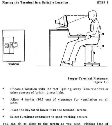
Placing the Terminal in a Suitable Location STEP 3
*
*
*
*
WINDOW
Proper Terminal Placement Figure 1-3
Choose a location with indirect lighting, away from windows or other sources of bright, direct light.
Allow 4 inches (10.2 cm) of clearance for ventilation on all sides.
Place the keyboard lower than the terminal screen.
Select furniture conducive to good working posture.
You can sit as close to the screen as you wish, without fear of radiation. Tests performed on TeleVideo terminals by Underwriters Laboratories indicate tlley emit virtually no radiation and pose no health hazard.
Attaching the Keyboard
l ...
I
, , ,
,
,
,
,
,
,
.
,
,
,
,
, ,
,
I I
,
,
,
,
,
.
,
,
I ,
,
,
I I
I I
, I'
\ ; ;
"
...
_---STEP 4
Plugging In the Keyboard Figure 1-4
,Plug the ends of the coiled keyboard cable into the back of the keyboard case and the front of the terminal.
WARNING! Never disconnect or connect the keyboard when the
power is on. Doing so can seriously damage the terminal.
On the underside of the keyboard is an adhesive-backed bezel label.
If you reprogram the function keys (as described in Chapter 2), you
can write the new key codes on the label and stick it onto the keyboard above the function key row.
Connecting the 905 to a Computer
,
,
, ,
COMPUTER R5-232C PORT :
•
•
,
•
•
,
,
,
,
,
,
,
,
•
•
STEP 5
Computer Interface Figure 1-5
Make sure you are using the appropriate interface, as discussed at
the beginning of this chapter. For an RS-232C interface, connect
the cable between the 905 main port and the RS-232C port on the computer or modem. If you have to rewire the RS-232C connector
for proper communication with the computer, see Appendix
p.
Connecting Your Printer to the 905
I \,
PRINTER RS-232C PORT:
•
•
•
•
•
•
•
•
•
•
•
I I I I I
RS-232C PORT
STEP 6
PRINTER PORT
Printer Interface Figure 1-6
Check that your printer is set up to receive data through its serial
port (check that it has a serial port!). Connect an RS-232C
interface cable to the printer port on the 905 and the serial port on
the printer. See Appendix D for information on configuring the
cable connectors for proper communication.
Your application programs also affect printer operation. Check with a technician in your organization or your dealer or distributor if you have any questions.
Plugging In the 90S STEP 7
0:;;:: = =
3·PRONG OUTLET (U.S.A.)
Plugging In the 905
Figure 1-7
Make sure the power switch is off (white dot out) before plugging in the 905.
P·lug the power cable into the terminal first, then plug the cable into a grounded wall outlet.
NOTE: In the United States, use a 3-prong electrical outlet with a
National Electrical Manufacturers Association (NEMA) Standard
5-15R rating. If you use a two-prong adapter, make sure it is
properly grounded ..
Turning On the Power
ON-OFF SWITCH
Push the white dot on the power switch in.
STEP 8
Turning On the Power Figure 1-8
After a moment, the bell sounds; after 10 to 15 seconds the cursor appears.
Adjusting the Screen and Keyboard STEP 9
You can adjust the screen and keyboard to suit your work
environment. Figure 1-9 shows how to change the screen contrast
to suit your lighting conditions, tilt the screen vertically and horizontally, and flip out the keyboard supports for a more comfortable typing angle.
THE NEXT STEP
Adjusting the Terminal Figure 1-9
Before using the terminal, check its operating values, as described in the following chapter. Review baud rates for computer and printer, screen features, data word length, parity, and other features before attempting to operate the terminal.
2. SET UP
Review of the Set Up Process
En tering Set Up
Selecting a Set Up Menu Selecting a Set Up Field
Changing the Set Up Parameter Value Leaving Set Up
Setting Up the 905
Main Menu Print Menu Keyboard Menu Screen Menu
Miscellaneous Menu
Reprogramming the Function Keys Second Miscellaneous Menu
Reprogramming the Answerback Message
Set Up
2.2
2.2 2.2 2.3 2.3
2.4
2.5
2. SET UP
The 905 operating characteristics, called parameters, are preset at
the factory. But before the terminal can work properly, certain
parameters may need resetting to agree with your computer, printer, and application program. For example, if the terminal and computer don't communicate at the same speed, they can't communicate at all.
You can reset parameters in set up. First press the SET UP key,
then display a series of onscreen menus and change any desired
parameter values. If you are unfamiliar with set up, read over the
next section, "Review of the Set Up Process."
When in doubt about a particular parameter, don't change it.
Application programs often set terminal parameters for you
automatically. Refer to your computer and application program
manuals first, or consult a technician, to get specific information about your system. If you encounter an unfamiliar term in the lists of values, look in the glossary at the back of the manual.
These are the set up menu names and the parameters each menu controls:
*
MAIN -- Communications between terminal and computer*
PRINT -- Communications between terminal and printer*
KBD -- Keyboard features and compatibility modes*
SCREEN -- Screen form and attributes*
MISC -- More screen features; programming the function keys*
MISC2 Enhanced code compatibility; WordStar mode;reprogramming the answerback message
REVIEW OF THE SET UP PROCESS
The following example shows how to change the screen background from dark to light. This process applies to changing any number of parameters.
Entering Set Up
PRESS
B
+
~.
TO DISPLAY THE MAIN MENU.STEP 1
The SET UP Key Figure 2-1
Press SET UP (SHIFT and NO SCROLL simultaneously). This
displays the Main Menu.
You can enter set up any time, but terminal stopS. accepting incoming data until you leave set up.
Selecting a Set Up Menu
PRESS
~
TO MOVE TO THE SCREEN MENU.STEP 2
Selecting a Set Up Menu Figure 2-2
Press the UP or DOWN key to move to the previous or next menu.
Selecting a Set UlJ Field
PRESS,
B
TO MOVE TO THE BACKFIELDSTEP 3
Moving' to a Set Up Field Figure 2-3
Pressing LEFT or RIGHT highlights a field within a menu.
Changing the Set Up Parameter Value
~SPACE
BAR~
PRESS TO CHANGE THE VALUE
STEP 4
Changing a Value Figure 2-4
Press the space bar until the desired value appears in the field. Refer to the glossary at the back of the manual if you don't
understand what a value means. After changing the value, simply
move to the next field or menu, or leave set up.
Leaving Set Up
~
+
tW!l\
PRESS
b
b
TO LEAVE SET UPPRESS Y TO SAVE VALUES
STEP 5
Saving Set Up Values Figure 2-5
To leave set up and return to the normal operating state, just press SET UP again. The screen asks if you want to save the new set up values in permanent memory.
Press Y so your new values remain in effect until you change them in set up again.
If you press any other key, the values you changed remain in effect only until you turn off the power (or reset the terminal). When you turn the power back on, parameters return to the last values saved in permanent memory.
SETTING UP THE 905
Main Menu -- Communications Between Terminal and Computer
Baud rate Word structure Parity
Stop bits
Communication mode Handshaking
Transmit delay rate
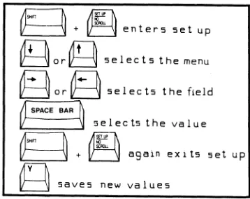
B
+~
enters set up~or~
selects the menu~or~
selects the field~SPACE BAR~
i-
~: ~~r:~::
::,'t:" .. t
"P~
saves new valuesThe Main Menu gives you control over communications between the
terminal and computer. These parameters must be set properly
before your terminal can transmit data to the computer. If you are
in doubt about a setting, don't change it until you consult the
manual for your computer or a technical specialist. See the glossary
at the end of the manual for detailed descriptions of each parameter.
Set Up 2.5
Main Port Parameters Table 2-1
Field/
Parameter Default Value Selections
Baud rate BAUD 9600
Word structure WORD 8
Parity PRTY NO
Stop bits STOP I
Increments from 50 to 19.2K baud.
7 or 8 bit data words
ODD, EVEN (transmitted and
received); MARK, SPAC (transmitted); NO parity.
I or 2 stop bits
Communication COMM FDX FDX (full), HDX (half), BLK (block).
mode
Handshaking PRTC X-ON X-ON, DTR, or NO.
protocol
Transmit XDL Y 0 Zero through 3 character delays.
delay rate
Print Menu -- Cominunications Between Terminal and Printer
Baud rate Word structure Parity
Stop bits
g
+~
enters set upt1TlIFl\
~orlt::j selects the menu
~
or~
selects the field~ SPACE BAR
1\
1/ -\J s e I e c ts the va I u e
g
+~t: ~
again eXl ts set up~
saves new valuesThe Print Menu controls communications between the terminal and
attached printer. As in the Main Menu, these parameters must be
set properly before your printer will operate with your 905. Consult a technician or your printer manual before changing any parameters. If you are unsure of a value, don't change it. See the glossary at the end of the manual for detailed descriptions of each parameter.
1::-
r
BAUDJ
.. _ ....
XL
PR I NT 1 200 WORD 8
Printer Port Parameters Table 2-2
Field/
Parameter Default Value
Baud rate BAUD 1200
Word structure WORD 8
Parity PRTY NO
Stop bits STOP 1
Set Up
foRTY NO
H
. stop...
Selections
...
1
1.
Printer Port Menu Figure 2-7
Increments from 50 to 19.2K baud.
7 or 8 bit data words.
ODD, EVEN, MARK, SPAC, NO 1 or 2 stop bits.
Keyboard Menu -- Keyboard Features; Compatibility Modes
Keyclick Key repeat
Editing key mode
.DOWN key cod~
Character sets Code compatibility
~t1f1
L : : j + E j enters set up
~or~
selects the menu~
or~
selects the fieldO-SPACE BAR ~
f
~: ~'~r:~,h:
::,'t:" ,.t
op~
saves new valuesThe Keyboard Menu controls key operation and code compatibility
modes. Most parameters are a matter of choice, and may be
changed by your application program. The glossary explains each
parameter in detail. See Appendix G for a summary of commands recognized by the terminal in each mode.
Set Up 2.8
Keyboard Parameters Table 2-3
Field/
Parameter Default Value
Keyclick KLIK EN
Key repeat REPT EN
Editing key EDTK DUPE
mode
DOWN keyl DOWN "/V
mode
Character CHAR U.S.
set2
Programming COMP 905
compatibility
Selections
EN (most keys click when pressed), DIS (keys are silent when pressed).
EN (most keys repeat), DIS (no keys repeat).
DUPE (editing key codes go to computer in full or half duplex modes), LOCE (key codes go to terminal only, even in conversational modes).
"/V (DOWN key sends cursor down
command);
"/J
(DOWN key sends linefeed comma.nd).
U.S. ASCII, U.K. (United Kingdom), FREN (French), GERM (German), SPAN (Spanish), FINN (Finnish), NOR W (Norwegian), IT AL (Italian).
Compatibility mode can be TeleVideo 905 or 910, Hazeltine 1410/1500, Viewpoint A2, ADDS Regent 25, ADM 3A/5. OR QVT-IOl.
lComputers may use a line feed code as a delimiter. add a line feed to each carriage return. or add a carriage return to each line feed. Consult your computer manual.
2Each foreign character set is available in an option kit
containing keycaps and EPROM See Appendix K for the foreign
character set keyboards.
Screen Menu -- Screen Display Features
Word wrap Autoscroll
Light or dark background Cursor appearance
Line or page base attributes Time-out blank
Carriage return
g
+~
ent'ers set up~or~
selects the menu~or§
selects the field~ SPACE BAR
1\
V--
i
selects the value~
+~i! ~
again ex i ts set up~
saves new valuesThe Screen Menu gives you control over a variety of screen display
features. These parameters should be set to best match your
application program. Check the glossary for detailed information
about screen parameters.
Regardless of how you set screen parameters, your terminal should be able to communicate with the computer. assuming the Main Port parameters described in Table 2-1 are properly set.
Set Up 2.10
Screen Parameters Table 2-4
Parameter
Word wrap
Autoscroll mode
Screen background
Cursor appearance
Attribute base
Time-out or blank
Carriage return!
Field/
Default Value Selections
WRAP EN
SCRL EN
ENabled (cursor wraps to the start of the next line), DISabled (no wrap).
ENabled (unprotected data can scroll off the screen), DISabled (data cannot scroll off the screen).
BACK DARK DARK (background is dark with light characters) or LITE (light with dark characters).
CURS BBLK BBLK (blinking block), SBLK (steady
block), BUND (blinking underline), SUND (steady underline), NO (in visible).
BASE PAGE PAGE (attributes affect data from the
cursor to the end of the page); LINE (from cursor to end of line).
TOB DIS DISabled (screen always remains on),
ENabled (screen blanks after 15 minutes of inactivity)
CR CR CR (RETURN key sends carriage
return only), CRLF (line feed and carriage return).
lComputers may use a line feed code as a delimiter, add a line feed to each carriage return, or add a carriage return to each line feed. Consult your computer manual.
Miscellaneous Menu -- Function Key Programming; Screen Features
Hertz rate
Status line appearance
Saving function key messages Reprogramming the function keys
g
+~
enters set up~or~
selects the menu~
or~
selec ts the fieldt'f"""SPACE BAR ~
II-
"\J selects the valueB
+~t; ~
again exi ts set up~
saves new valuesThe 16 function keys can send 32 separate messages, since pressing a key alone sends a code, and pressing the same key with SHIFT
sends a different code. The unshifted keys can be
reprogrammed--you can change the code that the keys send.
Detailed instructions for reprogramming the function keys follow Table 2-5. Before changing the function key messages, decide if you want to save the new messages in permanent or temporary memory. Messages in temporary memory are destroyed when you turn off or reset the terminal, and the keys return to default values. Messages saved in permanent memory remain until you change them again.
Two screen parameters--status line and hertz rate--are also included in this set up menu.
Set Up 2.12
Miscellaneous Parameters Table 2-5
Parameter
Status line appearance
Hertz1
Saving key contents
Field/
Default Value Selections
ST AT EN ENabled (status line appears on the
25th line during normal operation); DISabled (25th line is blank).
HZ 60 Screen refreshes at 50 or 60 hertz.
SAVE ON ON (function key contents are saved
in permanent memory); OFF (key contents are not saved).
Reprogramming F 1 = 1 SH@CR See instructions following this table.
function keys
ISelect 60 hertz for most of the United States and Canada and
50 hertz for most other locations. If in doubt. consult a technician.
Reprogramming the Function Keys
1. Position the cursor on the SAVE field in the Miscellaneous
Menu.
2. Press the space bar to select ON (permanent memory) or OFF
(temporary memory).
3. Press RIGHT to highlight the reprogramming field.
4. Press any unshifted function key to select it for
reprogramming. The key number, a code (I, 2, 3) that
indicates the destination of the function key message, and the cu.rent message appear in the field.
WARNING! The following step destroys the function key message
currently displayed in the set up line. Be sure this is what you
want to do.
5. Press the CE key to erase the present function key message
~ and begin loading a new message.
6. Press I, 2, or 3 to choose where the message goes whenever
you press the function key:
Code Destination
1 Message goes to the computer
2 Message goes to the terminal
3 Message goes to both computer and terminal
7. Enter any combination of characters and commands for the new
message. Each key can hold up to seven bytes. If you make a mistake, press ENTER, then CEo This restarts the process.
8. Press ENTER to end the loading process. You can then leave
the field or exit set up.
On the underside of the keyboard is an adhesive-backed bezel label. After you reprogram the function keys, you can write the new key
codes on the label and stick it onto the keyboard above the function
key row.
Second Miscellaneous Menu -- Answerback Message; Changing Modes
Enhanced compatibility mode
WordStar mode
Coding the answerback message
g
+~
enter5 5et up~or~
5elect5 the menu~or~
5elects the field~ SPACE BAR~
B
~ ~~r:~::.V:,'t:·,.t"P
~
5ave5 new value5Your computer program may require an answerback message from the
terminal. You can load an answerback message in this menu.
This set up menu also lets you enable WordStar mode, in which many editing and function keys send WordStar commands instead of
their normal codes. Appendix H contains a list of the keys that
send WordStar commands during WordStar mode.
Appendix G shows which codes the terminal recognizes in enhanced compatibility mode.
i;-MisC2r- ENHN DIS jWSMDDISr
Set Up 2.15
ANS8=
I
Miscellaneous 2 Parameters
Table 2-6
Parameter
Enhanced code
compatibility
WordStar mode
Field/
Default Value Selections
ENHN DIS DISabled (only basic code sets
available); ENabled (code sets enhanced).
WSMD DIS DISabled (WordStar mode disabled);
ENabled (function and editing keys send WordStar commands).
Reprogramming ANSB
=
the answerback message.
See instructions following this table.
Reprogramming the Answerback Message
1. Enter set up and press DOWN until the Second Miscellaneous
Menu appears.
2. Press RIGHT to move to the ANSB field.
3. Press CE to begin loading the answerback message.
WARNING! message!
Pressing CE clears any existing answerback
4. Enter a new message (characters or commands) at the
keyboard. It can contain up to eight characters.
If you make a mistake, press ENTER, then CEo This restarts
the process.
5. Press ENTER to end the loading process. You can then leave
the field or exit set up.
3. OPERATING THE 90S
The Keyboard
Alphanumeric Keypad The Numeric Keypad The Editing Keypad The Function Key Row
Editing and Sending Data
Communication and Editing Key Modes Sending Data to the Computer
Printing
Resetting the Terminal
Screen Appearance
The Cursor Screen Sa ver The Status Line
Operating the 90S
3.1
3.2 3.2 3.2 3.3
3.4
3.4 3.5 3.6
3.7
3.7
3. OPERATING THE 90S
This chapter describes how to operate the 905, including details on the keyboard, editing, printing, resetting, and screen/cursor control.
Note that many of the functions described in this chapter can be
changed by your application program. If a feature described here
does not operate as expected, contact your system manager, consult the manuals for your computer and application program, or call your dealer or distributor.
THE KEYBOARD
FUNCTION KEY ROW EDITING KEYPAD
I
~---4\---I---~\~\
ALPHANUMERIC "TYPEWRITER" KEYPAD
The 905 keyboard has four keypad areas. briefly explain the keys in each keypad. detailed description of key operations.
Opera ting the 90S 3.1
D
.
[]~[][J
·
EJ[]~D
EJ[]EJEJ[]:
LJEJDi
\ /
I
NUMERIC "ACCOUNTING" KEYPAD
The 90S Keyboard Figure 3-1
The following sections
Alphanumeric Keypad
This area of the keyboard is ptos't similar to an ordinary typewriter keyboard. ,All the alphanumeric and most of the other keys here repeat when pressed for more than one-half second.
The arrow keys, HOME, TAB,BACK TAB, BACK SPACE, RETURN, and LINE FEED move the cursor. The section in this chapter called "Printing" explains the PRINT key.
The operation of most other keys--ESC, CLEAR SPACE, CTRL, BREAK, DEL, FUNCT--is usually determined by your application
program. Check your computer or program manuals for the
functions they assign these keys.
The Numeric Keypad
This area of the keyboard is an accounting-style keypad (note the 0
and 00 keys and the raised center on the 5 key). However, some
programs may change the operation of these keys.
The TAB and ENTER keys work much the same as the TAB and
RETURN keys on the alphanumeric keypad. Your application
program usually controls the CE key.
The character and TAB keys repeat.
The Editing Keypad
This area contains six editing keys whose names describe what they
do--CHAR INSERT means Character Insert, and so on. These and
the PAGE key are usually controlled by your application program.
The SET UP key enables set up mode (described in Chapter 2). Press NO SCROLL to stop and start the flow of data coming in to the screen from the computer.
The SEND and RESET keys are explained later in this chapter in the sections "Sending Data to the Computer" and "Resetting the Termina1."
Operating the 90S 3.2
I
I
The Function Key Row
The function keys can be very useful to both programmers and
operators. The terminal does not recognize their default codes
(messages) as commands, so programmers can include the codes in a program for various special purposes.
The 16 function keys can send 32 separate codes, since pressing a key alone sends a code, and pressing the same key with SHIFT sends a different code.
But the unshifted function keys are reprogrammable; that is, the
codes they send can be changed by the user. You can load rry
message or command you like into a function key, such as a password, logon sequence, access code, or frequently typed words and phrases. You can program the function keys yourself, or your application program may do it for you.
After you reprogram the keys, you can write the new key code~ on
the adhesive-backed bezel label that comes taped to the underside of the keyboard, and stick the label onto the keyboard above the function key row.
Turn back to Chapter 2 (following Table 2-5) for directions on programming the function keys at the keyboard.
The function keys do not repeat.
EDITING AND SENDING DATA
Review the manuals for your application program or computer for instructions on editing and sending data, since programs often
control editing keys and operations. The following information is
very general and may not apply to your environment. Chapter 5
contains more technical descriptions of terminal operations.
Communication and Editing Key Modes
Before trying to edit. or send data, you should understand the 905 communication and editing key modes. You can change these modes in set up, but if you are unsure of which to use, don't change them. Your application program also often determines the editing and
communication modes. See the troubleshooting suggestions in
Chapter 4 if double characters or no characters at all appear when you enter data.
Full duplex:
Half duplex:
Block:
Most "interactive" application programs (those where you enter commands or data and the computer responds) work best with the 905 in full duplex communication mode. Your 905 is set for full duplex mode when it comes from the factory.
In full duplex, the terminal sends the key code only to the computer and not to the terminal. However, computers often "echo" key codes back to the terminal, so the printable characters you type appear on your screen, and special keys can control the
terminal. But remember, your application program
often changes how keys work.
If your computer does not echo key codes back to
the terminal, you can set it for half duplex. Then
the terminal sends key codes both to the computer and to the screen.
Data you enter goes only to the screen until you
send it to the computer by pressing the SEND key.
However, the terminal can still receive any data the computer sends.
Editing key: Editing keys control editing operations and cursor
movement. Appendix F lists the editing keys and
explains more about them. Editing key mode affects most, but not all, editing keys. In local editing key mode, editing key codes go only to the screen, even when the· terminal is in full or half duplex mode. In
duplex editing mode, the editing key codes are
handled the same as other characters you type--they go to the computer and/or the screen, depending on the communication mode.
Sending Data to the Computer
The SEND key sends screen data to the computer when the terminal is in block mode (explained in the previous section).
For a page send, press SEND. All data through the cursor position goes to the computer.
For a line send, press SHIFT-SEND. through the cursor goes to the computer.
Data on the cursor line
Page Send
Operating the 90S
CURSOR
lLiNE
~~~~~~nllnllll
C)'lIulio "L -_ _ _ _ _ _ _ _ - . _ _ _ _ _ _ _ _ ~" I
DATA SENT BY SHIFTED SEND KEY DATA NOT SENT
3.S
Line Send
Printing
Pressing the PRINT key sends the screen display to a printer
attached to the terminal. This is called a page print.
For a formatted page print, press PRINT. Each line sent to the
printer ends with a carriage return and line feed.
For an unformatted page print, press SHIFT-PRINT. Without
formatting controls, the appearance of the printed output varies, depending on the amount of space characters the screen contains.
A"'AAAAA'" 8888888'8.8888
cccccccc
D D D D D D D D DIl---t----CURSOR
AAAAA.AAA . 8 ' 8 . 8 8 8 8 8 8 ' 8 a
cccccccc
DOODDODDDO
AAAAAAAABB88B88888S8BBCCCC CCCCDQDDDDODDD
a. Screen Data
b. Formatted Page Print
c. Unformatted Page Print (Sample)
How the PRINT Key Works Figure 3-3
During a page print, the screen does not accept new data from the computer or keyboard. When the page print finishes, data can again flow onto the screen.
If you have a problem with printing, see the troubleshooting suggestions in Chapter 4.
RESETTING THE TERMINAL
For a full reset, press CTRL-RESET. This has the same effect as
turning the terminal off and back on again. All operating
parameters return to the last values saved in permanent memory.
For a partial reset, press CTRL-SHIFT-BREAK. This disables write
protect, protect, and the print mode; returns the terminal from block mode to the previous duplex communication mode; restores communication between the terminal and the computer (if previously halted); unlocks the keyboard; and sounds the bell.
SCREEN APPEARANCE
When you turn on the terminal, you see the cursor and the status
line.
The Cursor
The cursor indicates the position of the next entered character. It
can be steady or blinking, block or underline, or invisible. You
select its appearance in set up.
The UP, LEFT, DOWN, RIGHT, TAB, BACK TAB, HOME, LINE FEED, RETURN. ENTER, and BACK SPACE keys move the cursor.
Screen Saver
If you enable the screen-saver feature in set up, the screen blanks
after 15 minutes of inactivity. Blanking the screen conserves the
phosphor coating inside the face of the screen. Any new data from the keyboard or host makes the display reappear.
The Status Line
In normal operation the status line appears at the bottom of the
screen. It summarizes the current terminal operating characteristics.
Most fields are normally blank; information appears only when appropriate.
Your application program may let you display a user message in
place of the status line. Turning off or resetting the terminal
erases the message.
Figure 3-4 shows a status line with only the default messages. Note
the communication mode (FDX) in the 10th field. Appendix J
explains all the status line messages '-that may appear.
Operating the 905
3.8
4. MAINTENANCE ANn ASSISTANCE
Trou bleshooting
Running the Self Test
Checking and Replacing the Line Fuse
If You Need Assistance
Service Under Warranty Shipping the Terminal
Maintenance and Assistance
4.1
4.4 4.5
4.7
4. MAINTENANCE AND ASSISTANCE
TROUBLESHOOTING
Your 905 terminal is engineered to provide years of service. Occasional problems are usually the result of some cause other than
a fault in the terminal. If you have a problem with your 905, find
the symptom in Table 4-1 and try the solution listed there before
placing a service call. If you can't solve the problem yourself, call
your dealer or distributor.
Troubleshooting Terminal Problems Table 4-1
Symptom
Terminal dead (no bell; no cursor)
Possible Solution
Unplug power cord and plug in both ends again.
Check the line fuse; replace if necessary (see the instructions in this chapter).
Turn on power switch.
Check the terminal voltage setting (on the shipping carton).
Terminal does not Make sure system is "up."
go on line
Disconnect all cables and check for damage, then reattach.
Reset the terminal.
Make sure the terminal is not in block mode (check the set up menu).
Check the main port set up line to see that terminal communication values match your computer communication format.
Troubleshooting Terminal Problems Table 4-1 (continued)
Symptom
Terminal does not go on line
Cursor does not appear
Computer does not respond while on line
No keyboard response
Keyboard locked up
Possible Solution
Check computer port pin signals (see Appendix D). Ensure that pins 1, 2, 3, and 7 are
connected as specified. Pins 5, 6, and 8 must
be driven by +12 volt dc power or be
disconnected.
Turn on the modem.
Connect a different modem.
Check handset position in modem cradle.
Adjust screen brightness.
Check cursor style in set up.
Set baud rate, parity, word structure, and stop bits to match computer requirements.
Check cables connecting the terminal to th computer.
Unplug and reattach both ends of keyboard cable.
WARNING! Do not unplug the keyboard cable while the terminal is turned on. A power surge may result, which could severely damage the terminal.
Try half duplex communication mode.
Review all set up line values.
Reset the terminal.
Troubleshooting Terminal Problems Table 4-1 (continued)
Symptom
Printer does not print correctly
Escape and control codes do not function as expected
Display is wavy or bell sounds unusual
Possible Solution
Check communication values shown in the main and printer port set up menus against your computer and printer communication format.
Are the communication, editing key and print modes set so the terminal receives the PRINT key codes and printing commands?
Check that the cable connecting the terminal and printer is properly connected.
Check printer port pin signals (see Appendix D). Ensure that pins 1, 2, 3, and 7 are connected as specified. Pins 4 and 20 must be driven by
+ 12 volt dc power or disconnected.
Check escape sequences and control codes.
Make sure upper- and lowercase letters are entered correctly. Is a one used instead of a lowercase L? Zero for uppercase a?
Make sure the ALPHA LOCK key is not engaged.
Disconnect the cable from the terminal main port and loop main port pins 2 and 3; try operating in full duplex.
Try ESC sequences with LaC ESC key.
Change hertz setting.
Running the Self Test
You can verify proper operation of the terminal video display
circuitry by running the self test. The test shows all displayable
characters and visual attributes.
NOTE: Running the self test erases any data on the screen.
1. Press (in sequence):
SET UP 1
2. Watch for the test screen to appear.
Maintenance and Assistance 4.4
3. Check the screen:
*
*
*
*
*
Four lines should blink.
All' characters (ASCII control and display; graphics) should be displayed.
Each character should be formed properly, with no extra or missing dots.
The screen should show all the visual attributes in both full and half intensity.
The firmware revision level should appear in the lower left corner.
4. Press SET UP to stop the test.
5. Press CLEAR SPACE to clear the test from the screen.
Checking and Replacing the Line Fuse
Figure 4-2 (next page) shows the terminal line fuse.
1. Turn off the power and unplug the terminal power cord from
the wall outlet.
2. Remove the fuse holder by unscrewing it counterclockwise.
3. Slip the glass fuse out of the holder and examine it.
If the thin wire inside the fuse is intact, the fuse should be
functional. If the thin strip is broken and/or the glass is
slightly black the fuse has blown and must be replaced. (A
totally black fuse can indicate a problem with the power outlet. If that happens, call your service technician.)
4. Replace and tighten the fuse holder.
5. Plug in the terminal power cord.
If the newly replaced fuse blows out immediately, do not replace it
again. Call your service technician.
•
.-..:
.
() )1---1:'
D
GOOD FUSE
BLOWN FUSE
Replacement fuse: loS-ampere slow-blow (110 volt) 0.75-ampere slow-blow (220 volt)
Maintenance and Assistance 4.6
IF YOU NEED ASSISTANCE
Your TeleVideo dealer can help you solve problems and obtain
service. Before calling your dealer, review the troubleshooting
solutions listed in Table 4-1 and check the operating parameters (go
back to Chapter 2 to review them). Try to place the terminal by
the phone. Have the terminal serial number, found on the rear of the case, and this manual at hand.
Service Under Warranty
. The terminal is covered by a limited warranty (see Appendix B). No
warranty registration is required. If you need #service during the
warranty period, call your dealer. Should you need to ship the
terminal to the factory for repair, ask your dealer to first contact TeleVideo and secure a Return Material Authorization.
Shipping the Terminal
Have your service technician check the integrity of the cabling and
the security of the internal mounting hardware. Repack the
terminal, using either the original TeleVideo shipping container or other suitable materials.
5. PROGRAMMING THE 905
Entering Commands
Sending Commands From the Host Entering Commands From the Keyboard Command Format
Verifying Operations Self Test
Monitor Mode
Resetting the Terminal
Keyboard and Bell
Locking/Unlocking the Keyboard Editing Key Mode
Keyclick
Sounding the Bell
Screen Appearance Screen Visibility Screen Background Cursor Style
Visual Attributes Special Graphics Mode
Editing Modes
Write Protect and Protect Modes Creating a Protected Form Autoscroll Mode
Cursor Control
Line Feed and Reverse Lille Feed Cursor Movement
Addressing the Cursor Reading the Cursor Cursor Home
Tab Stops
Setting Tab Stops Clearing Tab Stop(s)
Moving the Cursor to a Tab Stop
Editing Data
Inserting Data Deleting Data Erasing Data Clearing Data
Communicating With the Computer Selecting a Handshaking Protocol Communication Modes
Setting the Communication Mode
Sending Screen Da ta in Block Mode Delimiters
Reprogramming Delimiters Text Markers
Sending Data
Loading and Sending Messages Displaying the Message Line Loading the Message Line
The Default Function Key Codes Reprogramming Function Keys The FUNCT Key
Sending the Terminal Identification Sending the Answerback Message
Printing
Print Modes and Protocols Print Commands
Page Print Terminator
5. PROGRAMMING THE 905
The 905 command set is compatible with the TeleVideo model 925
code set. It contains additional commands that control the added
features of the 905, and has omitted some unnecessary 925
commands. Other programming modes (selected in set up) are
compatible with TeleVideo 910, Hazeltine 1410 and 1500, Lear Siegler ADM-3A/5, Qume QVT-I0l, and ADDS Viewpoint A2 and Regent 25 code sets.
This chapter describes the operation of the 905 command set.
Appendix G lists all code sets. and Appendix F lists the codes
transmitted by the editing keys in each mode.
Most reprogrammed operating values are not saved in nonvolatile
memory (exceptions. such as function keys and page print
termination character. are noted in their descriptions). Resetting
the terminal destroys the reprogramming.
Some reprogrammable operating values. however. can also be changed in set up (the section called "Command Format" tells how to identify these values). When you change a set up value with a programming command. the set up line reflects the change. If you then enter set up and save the set up line values. the reprogrammed value is stored in nonvolatile memory.
NOTE: It's often convenient to change an operating feature by
commanding the terminal directly (Iocally) from the keyboard. If
you are not experienced in sending commands locally. read the subsection called "Entering Commands From the Keyboard" in the following section.
ENTERING COMMANDS
The terminal responds to commands sent from the host or entered at the keyboard.
When you enter commands from the keyboard, use the LOC ESC key instead of ESC, or put the terminal into block communication mode.
Sending Commands From the Host
The 905 terminal responds to control codes and escape sequences from the host regardless of your programming language format and syntax. How you incorporate commands into your programs depends on your programming language.
The multitude of languages and syntaxes recognized by each language makes it impossible to show you in this manual how to
incorporate commands in each program. If you need help with the
proper syntax, refer to the documentation for your programming language.
The Appendix C shows the ASCII characters and corresponding numeric values in various systems.
Entering Commands From the Keyboard
Sending programming commands from the keyboard lets an operator control many aspects of terminal operation not available in set up. Two factors affect the terminal response to commands from the keyboard:
*
Communication mode*
Correct keystrokesCommunication mode To ensure that commands from the keyboard go to the terminal, enable block communication mode. If you enter commands Cit the keyboard during full or half duplex communication
mode, the results are unpredictable. The computer receives the
commands, and its response depends on its application program.
However, you can send escape sequences to the terminal during full or half duplex mode by entering the commands with the LaC ESC key instead of ESC. This sends commands to the terminal only.
Correct keystrokes Always press the CTRL key first and hold it
down while you press the other key <as you would the SHIFT key).
Always press and release the ESC key before pressing the next key.
Enter characters exactly as shown. Notice whether the command
requires an upper- or lowercase character, a number one" or a
lowercase L, a zero or an uppercase O. Make sure the ALPHA
LOCK key is not locked.
Commands are printed in this manual with a space between the
characters. Do not type this space as part of the sequence; it is
included only for clarity. For example, the sequence
ESC c
involves pressing only the ESC key followed by a lowercase c.
Command Format
This manual presents programming commands in a format that shows the section title, values selectable in set uP. default values. the command function. the command in ASCII characters, and the equivalent key (if any). Of course. no one command has all these
elements. .
For example. look at the command to change the cursor style:
Cursor Style
Select cursor style
SET UP
DEFAULT Ps
=
1ESC. Ps
Cursor Style is the title of the section. Each section contains
one or more commands. All the commands that affect one
terminal function are grouped under a section title. listed in the table of contents.
SET UP indicates that the function or value can also be selected in set up.
DEFAULT Ps = 1 gives the default terminal condition.
Select cursor style defines the function of the command.
ESC • Ps is the command in ASCII characters. Variables in
commands are usually shown as Pn or Ps. Pn represents a
decimal value and Ps a selective value. Variable choices and their effects are listed in the descriptive text following each command.
The sixth element (not shown in the above example) is the keyboard key that sends the command code. For example, the command
Move the cursor right CTRL L
key RIGHT
means the right arrow key sends the code CTRL L.
VERIFYING OPERATIONS
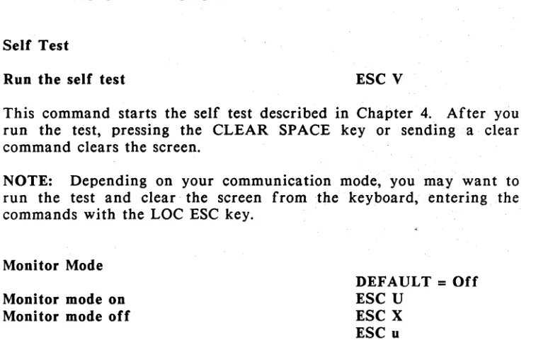
Self Test
Run the self test ESC V
This command starts the self test described in Chapter 4. After you run the test, pressing the CLEAR SPACE key or sending a clear
command clears the screen. .
NOTE: Depending on your communication mode, you may want to run the test and clear· the screen from the keyboard, entering .the commands with the LOC ESC key.
Monitor Mode
Monitor mode on Monitor mode off
DEFAULT
=
OffESC U ESC X ESC u
Mode on The terminal displays commands (control and escape
sequence characters) on the screen, instead of acting on them.
Mode off Terminal processes commands normally.
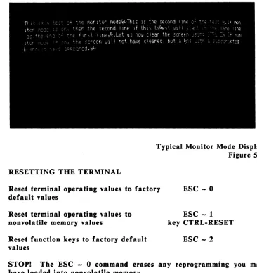
Figure 5-1 shows a typical monitor mode display. Seeing command characters on the .screen can help you debug a program. Appendix C shows how control characters appear on the screen in monitor mode.
If you want to display a control character without putting the terminal in monitor mode, send an escape character (or press LOC
ESC) just before the control character. .
RESETTING THE TERMINAL
Typical Monitor Mode Display Figure 5-1
Reset terminal operating values to factory default values
ESC - 0
Reset terminal operating values to nonvolatile memory values
Reset function keys to factory default values
ESC -1
key CTRL-RESET
ESC - 2
STOP! The ESC - 0 command erases any reprogrammi