.
, ",;; .. t. ":.i;l"#'.' .'" ~; . '".,~,~ .... ' ... / '
mini)Li5)) Li5=1min£lL
REPAiR AGREEMENT
The Mindless Terminal sold hereunder is sold "as is", with all faults and without any warranty, either expressed or implied, including any implied warranty of fitness for intended use or merchantability. However, the above notwithstanding, VECTOR GRAPHIC, INC., will, for a period of ninety (90) days following delivery to customer, repair or replace any Mindless Terminal that is found to contain defects in materials or workmanship, provided:
1. Such defect in material or workmanship existed at the time the Mindless Terminal left the VECTOR GRAPHIC, INC., factory;
2. VECTOR GRAPHIC, INC., is given notice of the precise defect claimed within ten (10) days after its discovery;
3. The Mindless Terminal is promptly returned to VECTOR GRAPHIC, INC., at customer's expense, for examination by VECTOR GRAPHIC, INC., to confirm the alleged defect, and for subsequent repair or replacement if found to be in order.
Repair, replacement or correction of any defects in material or workmanship which are discovered after expiration of the period set forth above will be performed by VECTOR GRAPHIC, INC., at Buyer's expense, provided the Mindless Terminal is returned, also at Buyer's expense, to VECTOR GRAPHIC, INC., for such repair, replacement or correction. In performing any repair, replacement or correction after expiration of the period set forth above, Buyer will be charged in addition to the cost of parts the then-current VECTOR GRAPHIC, INC., repair rate. At the present time the applicable rate is $35.00 for the first hour, and $18.00 .per hour for every hour of work required thereafter. Prior to commencing any repair, replacement or correction of defects in material or workmanship discovered after expiration of the period for no-cost-to-Buyer repairs, VECTOR GRAPHIC, INC., will submit to Buyer a written estimate of the expected charges, and VECTOR GRAPHIC, INC., will not commence repair until such time as the written estimate of charges has been returned by Buyer to VECTOR GRAPHIC, INC.,
signed by duly authorized representative authorizing VECTOR GRAPHIC, INC., to commence with the repair work involved. VECTOR GRAPHIC, INC., shall have no obligation to repair, replace or correct any Mindless Terminal until the written estimate has been returned with approval to proceed, and VECTOR GRAPHIC, INC., may at its option also require prepayment of the estimated repair charges prior to commencing work.
Repair Agreement void i f the enclosed card is not returned to VECTOR GRAPHIC, INC. within ten (10) days of end consumer purchase.
TABLE OF CONTENTS
Section
Repair Agreement Table of Contents I. Introduction
1.1 Specifications •••••••••••••••••••••••••••••••••••••••••••••••• 1-1
1.2 Description of the Mindless Terminal •••••••••••••••••••••••••• 1-2 1.3 Description of the Manual ••••••••••••••••••••••••••••••••••••• 1-2
II. Users Guide 2.1
2.2 2.3 2.4 2.5
Keyboard Controls ••••••••••••••••••••••••••••••••••••••••••••• 2-1 Installation •••••••••••••••••••••••••••••••••••••••••••••••••• 2-2 Cables •••••••••••••••••••••••••••••••••••••••••••••••••••••••• 2-6
Keyboard Code COnversion •••••••••••••••••••••••••••••••••••••• 2-8 Adjusting Procedure for ·the CRT •••••••••••••••••••••••• 2-9 - 2-12
III. Schematics
ASCII Code Chart •••••••••••••••••••••••••••••••••••••••••••••• 3-1
Interface Board in Mindless Terminal Schematic •••••••••••••••• 3-2
Monitor Schematic •••••••••••••••••••••.••••••••••••••••••••••• 3-3
Monitor Parts List and Components Layout •••••••••••••••••••••• 3-4
Keyboard Schematic ••••••••••••••••••••.••••••••••••••••••••••• 3-5
Keyboard Mechanical Assembly and Keytop Layout •••••••••••••••• 3-6 Keyboard Code Chart ••••••••••••••••••••••••••••••••••••••••••• 3-7
1.1 SPECIFICATIONS
Screen Size
Resolution
Bandwidth
Video Interface
Compatibility of Video
Keyboard
Keyboard Electronics
External COntrols
Internal Controls
Power
Power Source
Cables
Rev. O-B 3/30/79
I . IN'.rRODUC'l'ION
12-inch diagonal CRT
900 lines at center 750 lines at borders
12 MHz
Separate TTL video and sync
Compatible with Vector Graphic Flashwriters
I and I I alphanumeric video display
boards and most other alphanumeric video display boards
Not compatible with Vector Graphic High Resolution Graphics board
Custom 60 keys, typewriter format, 12-key numeric pad, ESC, DEL, ALL CAPS
CTRL, LF, and cursor movement keys
Capacitance key switches and LSI N-channel
MOS encoding electronics
COntrast
Vertical hold Height
Vertical linearity Vertical centering Focus
Brightness
Horizontal centering
+16V @ 1.15A +8V @ 0.25A
+16V and +8V from mainframe power supply
Purchased separately: cable to connect terminal to mainframe and to connect inside of mainframe to
power, to keyboard port, and to
video board
Vector Graphic Mindless Te:r:minal Users Manual
1.2 DESCRIPTION OF THE MDIDLESS TERMINAL
The Vector Graphic Mindless Terminal is a high quality terminal that, particularly when used with Vector Graphic video display boards, provides the user with features and versatility not available in other terminals.
The CRT monitor has up to 900 lines resolution and 12 MHZ bandwidth. All elements of the display are adjustable and adjustment procedures may be found later in this manual.
The keyboard is a high reliability unit with capacitive type switches. A numeric keypad and lighted shift lock and ALL CAPS lock keys are standard.
The Mindless Terminal is designed to receive power (+8V and +16V) from the computer power supply. cables are available (ordered separately) which make these connections quite simple to implement.
The Mindless Terminal requires that the video information be provided at TTL levels as separate video, horizontal sync and vertical sync. This is provided by Vector Graphic alphanumeric video boards.
1 .3 DESCRIPTION OF THE MANUAL
II. USERS GUIDE
2.1 BX1'ERNAL CON'l'ROLS
Operation of the Mindless Terminal is very straightforward. The power to the Mindless Terminal is provided by the computer power supply and is thus switched on and off by the computer power switch.
The only external control is the contrast control located on the rear panel of the Mindless Terminal. This should be adjusted to suit personal preference and ambient light level.
For other adjustments see section on CRT monitor adjustments later in this manual.
Vector Graphic Mindless Terminal Users Manual
2.2 INSTALLATION
In additien to, the Mindless Terminal, yeu must erder separately the VMTC
cabl~. ~et, which includes:
,,). A 4 .. foet 25-cenductor .flat. ribben ca.ble used .te intercennect the
MiI)dless Terminal to, the. cemputer interface.
2. A signal/power cable assembly, used inside the mainframe chassis, to,
. connect. the termina.l. to, pewer supply and al so, previde the video, si9TIals and receive the keybeard sign<1;ls.
TERMINAL
25 CONDUCTOR
FLAT CABLE
fiGURE 1
COMPUTER
The fbllewing precedure describes hew to, cennect the Mindless Terminal to,
Vecter Graphic systems (such aS,the Vecter MZ) utilizing a Vecter Graphic
Flashwriter Video, Beard and the abeve mentiened VMTC cable. Wire lists are
previded fer the tiser to, fabricate cust~m cables fer cennectien to,
nen-standard devices. Please nete that due to, the large variatiens in
VIDEO
CONNECTOR
t·
nGtnE 2
INTERFACE
CONNECTOR
-:::::::::--
--:.:::::
~
+8v~+16V
~GND
KEYBOARD
CONNECTIONS
1. Eefore prc,=edi:l9', :a.mi::'iarize yoursel:: wi t::h the "-:'1TC cables and thi:;
mClnual.
Note ,:ha':: the internal cabl-= is divide 1. ir:to four parts: video c.::Jnne::tor; k",ybo:1rd conn-3cto::; power sup?ly connections; and interface conne'.:-:or.
2. M':>unt th<: DE-25S Interf=.ce Conr.eet')r in a con'.·ienent ::utout on t::e compm:er c"las:'s ba:kpa:lel tlsin::r the ha=dwa:-e s:.:pplied.
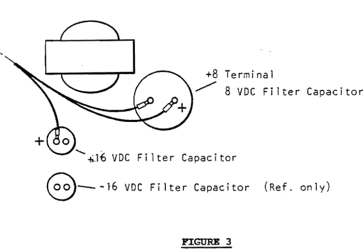
3. C)nnect -:-.he ?ower termi:1al lug mar::ed -'-SV ::0 t::e +SV termi',.3.1 on tr.e l~rge :il~er capacitor (se: Fi~ure 3). Ve::ify all ~f ~~e cthe: ter~in~l L:gs are :n pl.-3.ce :md ':ig1:-. ~ene i sa :ure::"y.
4. I:-. a ::"ike"ise :nanY'.er c;)nne:t t·.1e t:rmi-.al :'ugs ma'·:<.ec +1E1, a •. d G';D t,,)
t:-.eir :::"es:~ct:..,e c)nn.:::.:tic', pc':'nts as .;ho ... --. in Fig'.:.re .:.
Vector Graphic Mindless Terminal Users Manual
+8
Terminal~
8
VDC Filter Capacitor"-~.16
VDC Fi lter Capacitor8-
-16 VDC Fi Iter Capacitor (Ref. only)FIGURE 3
WARNING - It is very important that the power connections are made correctly. Failure to provide correct power may result in equipment damage.
5. Install the video board in a motherboard slot near the rear of the computer chassis to permit the video and keyboard cables to be connected to i t conveniently.
6. Plug in the 24 pin DIP plug connector into the keyboard connector socket on the video board. Note correct pin orientation as shown in Figure 4 •
••••••••••••
Notch
24
Dip Plug, . pin••••••••••••
pin
FIGURE 4
~
----,mooth surface
~_____
to the front
pin
pin 6
video board
F'IGURE 5
8. Check all connections; verify all boards are plugged into the motherboard. Connect the 25-conductor flat cable between the Mindless Terminal and the interface connector on the mainframe as shown in Figure
1. This completes the hardware connection of the Mindless Terminal.
Vector Graphic Mi.nd1ess Terminal Users Manual
2.3 CABLES
The following information is provided to help users connect the Mindless Terminal in non-standard situations. The "Interface Board" refers to the small PC board at the rear and inside the Mindless Terminal.
IN'1'ZRCORNECT CABLE - CRT MON:ITOR / INTERFACE BOARD
MONITOR INTERFACE BOARD
10 PIN EDGE 16 PIN DIP SIGNAL
1 15, 16 HORZ GND
5 12, 13, 14 GND
6 6 H SYNC
7 1, 2, 3, 4 +12 VDC
8 7 VIDEO
9 5 V SYNC
10 9, 10, 11 VIDEO GND
IN'l'ERCONNBC'l' CABLE - KEYBOARD
/
:INTER:FACE BOARDINTERFACE BOARD KEYBOARD
16 PIN DIP DUAL TEN PIN EDGE SIGNAL
1 C GND
2 C GND
3 5 DATA 8
4 6 DATA 7
5 1 DATA 4
6 4 DATA 1
7 N/C PRESET
8 2 DATA 3
9 10 -V REG
10 E STROBE
11 D GND
12 7 DATA 6
13 3 DATA 2
14 8 DATA 5
15 9 VCC
J2
-6
PIN MQLEX
INTERFACE
CONNECTOR
~---
.• --...~+8
~~+16
~GND
13
12
2~ PIN 0 I P _PLUG
INTERNAL PORTION OF VMTC
WIRE
. FROM TO GUAGE SIG~AL
J2-2 J1-14 22 VIDEO GROUND
-3 -15 TTL VIDEO
-4 -16 TTL HSYNC
-5 -17 TTL VSYNC
J3-7 J1-20 22 KYBD DATA 1
-8 -21 DA':'A 3
-9 -22 -V REG
-11 -24 PRESET
-12 -25 STROBE
-13 -12 GND
-14 -1 1 DATA 4
-15 -10 DAT.l\ 6
-16 -9 DATA 7
-17 -8 DATA 2
-19 -6 DATA 8
-20 -5 DATA 5
+BV J1-1 18 POWER +8V
vee
UNREG+16 -18 +16
vee
UN REG+16 -19 +16
vee
UNREGGND -2 GROTJND
Gm) -3 GROUND
Vector Graphic Mind1ess Terminal Users Manual
2.4 lCBrBOARD CODE CONVKRS:IOH
Due to limitations in the keyboard encoder chip, i t was not possible to provide several codes, in particular, those for the following characters:
[ (SB)
] (SD)
\ (SC)
(7E)
The conversion can be done in software, as the [] key generates unique codes
for the four modes: unshifted, shifted, control, control shift. This
conversion is done in the Version 3 Monitor PROM (purchased separately from
Vector Graphic), which is the companion PROM for this keyboard. Furthermore
2.5 ADJUSTING PROC:EDURE FOR CRT MONrroR
Normally, no adjustment of the CRT screen should be required as i t is adjusted at the factory. However, i f adjustment is required for any reason, the following explanation of the functions of the various adjustments is provided. All the adjustments except the last two must be made inside the Mindless Terminal, requiring you to unscrew and remove the shell.
I t is assumed that the terminal is connected properly to the computer. A display which can be used to check adjustment is obtained by depressing RESET on the mainframe front panel to call up the Monitor Executive, then, for the Flashwriter I board, by typing Z 0400 07FF 06, or for the Flashwriter II video board by typing Z 0000 07FF 38.
, . If the deflection yoke is not firmly against the bell of the tube, shadows will be caused at the corners of the display as shown below. If the yoke is slightly twisted, the display will also be twisted.
RASTER
Adjustment for this is made by first loosening the clamp screw holding the yoke and positioning i t properly. CAUTION: DO NOT TOaCH ANY OF THE ELECTRICAL TERMINALS ON THE TUBE OR YOKE, AS HIGH VOLTAGES ARE PRESENT. Tighten the clamp gently when finished.
.-CENTERI NG MAGNET
CENTER I NG ,u;;;!ltt---CLAMP _SCREW
MAGNET---
----tr---~--~~~~J
Vector Graphic Mindless Terminal Users Manual
2. If the width of the display is improper, adjust the core of the width
coil (L103) on the P.C. board.
r"
. ..,
J
I
I DATA I
L.t---1.
J
3. When data linearity in the horizontal direction is not good:
Wl
~A
A
W2
DATA
Turn the core of the horizontal linearity coil (L102) so that W
1
=w
2=w
3•4. When data runs in the vertical direction:
t
•
•
DATA
Turn the V. HOLD pot with a screwdriver and stop data display.
5. When the vertical size (height) of data is not proper:
r
Turn the HEIGHT pot (R110) with a screwdriver to adjust the height as required.
6. When vertical linearity of data is not good:
jilL-DATA
,
-H~-DA-rA
r.-rl j
F
=
c::;:t_-r-.-Turn the
v.
LIN pot with a screwdriver so that 81=82=83•
7. Raster deviation:
rt=~7
R;l,STER
I
I
\
L - - - J
Turn the two centering magnets so that the raster is centered in the vertical direction.
8. When data is not focused satisfactorily, turn the FOCUS pot (R122) with a screwdriver so that focusing of the entire picture is optimum.
9. The correct adjustment of the brightness potentiometer R117 is when the background raster is just barely extinguished (black). If you can see f3.int lines zig-zagging across the screen in the background, turn the brightness do'HTl..
10. 7he contrast pot on the rear of the chassis should then be minimum consistent with good legibility of the display. depend on the ambient light level and personal preference.
Rev. O-B 3/30/79
set to the This will
Vector Graphic Mind1ess Tezmina1 Users Manua1
11. The horizontal positioning is controlled by both the video CENT (A103) control and also the position control on the upper left hand corner of
1968 ASCII: American Standard' Code for Information Interchange. Standard No. X3.4-1968 of the American National Standards Institute.
b7
-I
0
0
I0
Bits
b,
• 0
0
1
bs
I0
1
0
_:
t4t3~~1
t.OWt,
..
0
1
2
000.0
0
NUL DLE SP
0001
1
SOH DCl
1
0010 2
STX DC2
II001 1
3
ETX DC3
#
0100
4
EOT DC4
$
o
1 0 1
5
ENQ
NAK 0/0
o
1 1 0
6
ACK SYN
&
o
1 1 1
7
BEL ETB
,
1000 8
BS CAN
(
100 1
9
HT EM
)
1 0 1 0
A
LF
SUB
*
1 0 1 1
B
VT ESC
+
1 100
C
FF
FS
,
~
1 1 0 1
D
ICR GS
-1 -1 -1 0
E
SO RS
•
1 1 1 1
F
SI
US
/
\. ¥
All characters in these two columns and SP (Space) are non-printing.
L
G=l4P1-iC inC.
NOI athhaled WIlli Vector General, Inc.
Rev. O-B
0
1
1
1
I1
1
0
0
1
1
1
0
1
0
1
3
4
5
6
7
0
@)
P
,
•
I1
A
Q
•
CI
2
B
R
It
r
3
C
S
I
C
•
4
D
T
cI
t
5
E
U
•
u
.6
F
V
f
y
7
G
IW
•
•
8
H
X
h
X
~9
I
Y
I
Y
•
J
Z
J
z
•
•
K
[
II:
{
,
<
L
\
I
II
•
M
]
•
}
>
N
-
II
"'""
?
o
I _
•
DEL
When UPPER CASE ONLY is used, shaded lower case
characters (columns 6 & 71 from keyboard are converted to
their upper case equivalents (columns 4 & 51 before being
printed or transmitted.
Mindless ~er.minal Users ManU8i
A
'"
150
CONTRAST
.500
r-'\I'(V-j
DB-2.5P
_ _ .--.t1 I
150 PF
C) c)DIP
CRT
.... " 1
~
TIL Y
IDEO
15
I--... -J\ v - " ' - - - t - + - + _7
-+-+---1
8
IHSYNC
161---~-7-0---~-+-r-6~-+---~
6·
!
YSYNC
17
5
-+-+---1
9
GND 1.04
1---~
100p.H...
--+-9-16
; - 1510
_ _+16 18
-
.~
-
-
1---+-+--+-1-~
7
+16 19
U
0.1
T~
+
d:~.7/50
7812
MONITOR
...:....
GND
2
-GND
3
U
--~.
7/.50
DIP
KY.! I
+
8
1
+-T,
7805
1---....
,5, 16
-+-.f---t9
rD
GND
12 1 - - - + - 1 , 2 . 1 1
C
ii
DATA
8
6
3
5
!I
DATA
7
9
~
6 I
DATA
~11
5
1
DATA
1 20
6
..
PRESET
2'-
7
__+_+-N/C
DATA
3 21
8
-+-+---;
2
-Y
REG
22
9
10
STROBE
25
10
E
DATA
6 10
12
7
DATA
2 8
1-13
3
DATA 5
5
1.04
8
----KYID
SPECIFICATIONS
MODEL CIQ-9
MODEL CIQ-12
g"
and t2"CRT
DISPLAY
MONITOR
~
c.
ITOH ELECTRONICS, INC.
5301 8eetl'loven Street Los Angeles. Calif. 90066 TelephOne: (213) 390-7778 Telex: {WU165·2451
SPECIFICATIONS
GENERAL
The Model CIQ-12 and CIQ-g are a 12-inch and 9 inch CRT Display Unit is to be used as an alpha-numeric display device. The CRT will be scanned in conventional TV fashion.
All input signal connections to the monitor will be via a single 10 pin card edge connector, and comprise:
RATING
1. Video Input
2. Video Input Impedance
3. Horizontal Drive
4. Horizontal Drive Input Impedance
5. Vertical Sync.
6. Vertical Sync Input Impedance
7. Signal Level
8. Power Supply
Video
Horizontal Drive
Vertical Sync
4.0Vp-p :: 1.5V positive going pulse
More than 1 K.o
4.0 Vp-p
=
1.5V positive going pulse Pulse width: 4 to 40 JJ.Sec.Frequency: 15.75 KHz =500 Hz
More than 470.0
4.0 Vp-p :: 1.5V negative going pulse Pulse width: 300 ,usee. to 1.4 msec. Frequency: 55 Hz =8 Hz
More than K!1
Low: 0:: 0.4V High: 4 = 1.5V
DC +15V :: 0.2V (Less than 1.2A)
or DC +12V :: 0.2V (Less than 1.5A) or AC 115/230V
=
10%,50/60 Hz (Option)Input connector for AC power supply (customer supplied).
10. Humidity
11. C.R.T.
12. X -ray Fiadiation
13. Weight
14. Dimensions
15. Inside Controls
16. Phosphor
CHARACTERISTlCS
1. Video Band Width
2. Rise Time And Fall Time
3. Storage Time
4. Horizontal Retrace Time
5. Vertical Retrace Time
6. Resolution
10 to 90% (Non-condensing)
12 and 9-inch, 90" deflection 20·
Less than 0.5mR/H
C1Q·12
Approx. 9.9 Ibs (4.5 Kg) without AC power unit AC power unit Approx. 3.3 Ibs. (1.5 Kg) CIQ·9
Approx. 6.2 Ibs. (2.8 Kg)
Based on the drawing of External View.
Sub-brightness Horizontal Centering
Focusing Horizontal Size
Vertical Frequency Horizontal Unearity
Vertical Size Vertical Linearity
P4 -Standard P31-Option P39-0ption
16MHz :: 3dB
35 nsec or less (linear mode)
15 nsec or less (linear mode)
Approx. 8.5 iJ.Sec.
0.9 msec. or less
CIQ·12
Center: 850 TV lines (mean) Corner: 700 TV lines (mean) CIQ-S
Center: 800 TV lines (mean) Comer: 650 TV lines (mean)
7. Distortion and Unearity Offset
Within limit equivalent to 2% measured with EIA's ball chart
(with PC board mounted according to manufacturers specification)
8. SN Fiatio 40dB or more (800
/0 area of CRT screen)
S. MTBF More than 20.000 H (without CRT)
10. Performance range COC to 40"C
1. Connection of Connector
I
H.D. -B Ground
I 1
r--Brightness
~
2
~---I
3 Brightnessr -
Brightnesso---J
B100KD 1/4W
4
~--I
5 Ground
t---L
~-
H.D. InputI
7 -i-15V, ..,..12Vr]
Video Input~~-I
9 V.D. Input~
V.D. Video Ground2. Input Connector
Card edge connector
• Viking #: 2VK10S/1-2
• Amphenol #: 225-21031-101
• Cinch #: 1-039-0119
• Hirose #: CR7E-20DA-3.96E
• Or Equivalent
Polarizing key shall be inserted between 9 pin and 10 pin.
3. C.P.U. Output Circuit
-i-5V
H.D.
+5V
V.D.
(O.C.)
220
Video
(O.C.) Coaxial cable
ILo
u:-
4VIII III
H.D.
Display Blanking
Data Input Signal
Horizontal (in .u.s)
(15.75 KHz)
Vertical (in ms)
v.o.
~
300 . . -1.Lf
Display Blanking
Data Input Signal
I
I
1
I
I
I
0.9
Data Canter
I
I
I
I
I
I'-.~
!
I
~RasterI
15.77I
I
WS.79-!
'
I
I
I
1
I
!
III
illl
!
/ I I
Data~
I
I
I
I
DisplayI
I
14.4I
I
16.67·1
I (1 V) ,
1 .. 0
L
(0
11101
ill.
QIOI ••
,f:J'-
'-:<31°1
.----l~
l!C'S"'14r=r----2
""'"
IF-~
111« 1114'
t()O b9
JI'It
5006
~ T~~~I ~::r:l-
I '~OP 11110.1.( 47
IIlOli
6&0
I ...
11104
loot<
r
v.o,d
~-+--1'-"""""'-l };,r .... "
J
QIO!>r-' ~'Ol Z5AIO,j
O.SW .w
- - - \ 1 I • - .
CI~?
.--____ -Jr
nr~
56101. 111"6u<
0.'''''
L-J,I
T.c,." ...
(;.f()~ 1kCJOIJ(''''P
I
~;: 'st.'" 010'1--1--('RT
I,' "JO· lOti
E1.110 M
M,I e.~p
::t:!q
_T Q.04 i:StU~$ltOi 0
!~:
RlOtl~C-.tlA
~~~~ ~~f
tll)'l
CA.,."U , .. '" 4.1" 'U!tl'~'1!'
RIO.;!;:;"
M
ICn_
1
~~I
v!
='
1-" .,,~ f.'l;. "III>
J:}J
\.lIO"I
' ..
r -J u(Oal$I
Err CRT6NO 1'M.'ll..:LI Rfln DRUtlff' ( ).... - - .
.. t v ,.., -II 'J'
~~"C)
':1~
~~~K
ItT
qlO," \I''''O~ O,5W ---"V\Iv--- " P tlC-ltttS 20k& lID$ ""no"," (
i---·.
ow.~ • • ~ I>l·U1 lOOk.
I
1,00KII.""DC VUH - - - ~ 'II RI:\!\ .ltr.(un) ~~~~
JPft
r~:1
JVfG
=~l:
lun~
i
~J-410K
~r--J
\1.1> :\:to ,::1 II, "I~O ll01
I
Rna.~ •• U 4.1 IR',aIS(II
i'OJ4v ~)K ) ' " 1~.l---1l~
D
-41-"""'j
VltI"2- -r""
til'~
1
...
1 (H)I
DY0" I ,til -lIlll 20K.
Mol
(1/9 IK (_I! P'(·1I10G0<'''4:., S 6K .. tu:,Hr ,0
I
J
-;;-Lr-~
t7V
(.~'Lt-·--"'e----~-RU, 10" /,6f4...
I
(v) A.N'v- '\AhV 6
r
":I,
11
u~f
I .
:~~~
~:
.~t._
....
"
I
I:>IO"UO)I
LIO~
Pl-lb\
II.LI ..
@
~
'Oz.+e-O .. , •
•
~
010 2ZtlF-\ O.SW
~
~bO0' ....
o
to
:~:"~'l~ ~'~
-
~~~OI5 ~ ~
<ID
2~l1f6I1T
""~\:!J
r-\ (.IIT\..1.1 <. RIZi
R~Dp, ~~O~'::Io~HK
III 25"CID
..)0"" .,
<ID
VI'"OI160 'M8
VflUQ
10K-&
010.
qg
CII"~llJ/'1 &.11;.
.,
l'tlS'
<-'
~CIOJ
~!>K
Q
tQI<ll
:';~
1111 E
~
"1"-
3.31< ~o
PO·BII CIO-12 AND 9 ISVOC VERSION COMPONENtS LOCATION
(COMPONENTS SIDE I
llO~
\)l: 21Sl>
nnnn rq
.1rR ••••L--.
t • .. CRTJooru~
.
I M~~ v.JI'Co GIIO'
ne,,...
I:l." "ld' 20~::'-1 E271D 84
I tSOCtC)
l •
t
II:I"~,_'-I i:lo-t
11:141
,00
0."
C''l.i!f
O.tH
. • tnbV
t:~(I"
~e
I lOOt<
•
T!;r~i----t-~-:~:!~----~---1L---1
1£'~I
Q~
.el~
II<
0<'"
Qlat
~~
~
~_.,.
.... 'IPI
:,.,..w
~J!l7
j
-rn'l
l- - - --
~~rIM
~ '~\P
",t-
IIUO' , ...~
""''''SI C 111"",.. 'I( . . 1 1 1 0 5 " . . l . . . ° <>1
~V,~ tlF-1 "'~ 1.4.
~iSl f:J.~
£X1I'U
J"
I
11110% •.uc-
~w
I
rwJ (.. 2$(181S'<oN!' .~ •• : ' ~ RI:\2 llI(Ju~T ..
I 211( 1134
It-'
cw-t12\1 .,ut(.) Rll7 ,::'01< 1<:155" I
t
I
o.
:,.,OK. l
QID6 vf'i\I03 (),I'W .... ".
1',""",,1t Ii 2~CISIs" 20K~ ~4J~3 1{1~;;:IV--IJ4
-"'-1"
,OOKI'""f"(;
V.LlN ".'IN ~~ ~ ~!["~7oF __________ o .. r.) ~. 2.70K ~ IJI'R
~::7
.mo Lle>4I
~t-_.J
D
.:
p,
:~
' ; ; ! "
MO'
,;
~'"
1r0~::'
=-'0 .... Jt,Ol. .. ~".
I
"I (II)Qv I
~~~rr
t;,' ",Cq(leJ'l::
._--,""",-"NV' 2~V I'j(ll -
-DY DY-H40 6
1m" """" (v)'''NV '""'"
Y <;NV
~~ n:~
I - (1-) IIea
5.'''' "'Wi . " " .. ~I< /f !i'i""..1:t---...J fPl
,.
~""i1.1:1 ___
-_--;~~--=;---:=---1
I
P'O. (1I1"
o
D,rtP
[
"221ft1
81)~'A~,ft
:]
'<t
oft_++_1-1
+~q
Nm
,...
",q
+10
Mit
,...
...
...
(I)uS
~
o
I 1'" 1 111111 _I
• .. 7.12610.04
MI~
a
~~:~~~L~;I
" /
Ca"ANGU DIMENSIONS ... 1 I .. ch I MOUff1 •
INQ
NO.
e
a b c IOLE.1 G' 14.521100791 .,512 IUsa 22113 10. 1111 I1t8SOl0J511 3G.t4 IAWII :I Ii" 14665tOD791 118.lll 11UI27to.ll1l 22UU 11'UJZ1IU51' 29814 IAIoa
31 1.5' 14.12410.0.791 181!1I 10..'111 I1l&J41011i11 12012 223313 2' lUll 4 ~
4 uf (4.164100.191 18.72410. ... 12.ll 221.13 1 IU4511O.1611 UIWII nlt4
•
15' (U6!itG01!11 .SUll IUUlo.nl, 246.213 111.IC210..1i11 28314 ~•
0' 14.5281G0791 11.1581 0.111, I1U114 10..51 1 USt2 2l1Sn 29U4 w..al' uf non 22o.IU 21014 IU24100nl ".68SI0.1111 IllG24101571 IAboID
•
u( 18D24*0.0191 163*2 1."5.110.111' 2U1U 0019110.1511 2slt4 ~21012 114\1tO.011
y-
-,.
- r
~~
l$I
:t
..
tV
"1
POWER UN" IOPTlONI
~-7rl. ~11.d.&J....
U
.-oo-ct·o-·
,
.
.,
_ _ ,'P"l _ _
tnc.h
•
NO.1 002
'J::::n
.~
~'-32,,", IAI N03 NO'!HOS NO."
N01 !fua
I':~-
r~',;:
.
Ir~.\·,;·
(9 ... ....
1, - , - : ' - : - - •I ';;;
.'~'I.'i-;;'~:
"'>
J CIQ'I2 SEflIESI~
311
-I.
_~.
_ _ _~
; ;:',I~_'
" ' .I
~~T~I~E
DIMENSION " . ! •~~
--
.. ~ ,o
257.0 Min.
281=3
R6:35
Cla~12 CATHODE RAY TUBE
DIMENSIONAL OUTLINE
External Conductive Coating (Note 2) (Note 3.4)
Umt: mm 288 Max.
26B
=
7 13 Max. 166=4 102=3109
Reterence Una (Note 1)
against the bulb.
2. External conductive coating and implosion protection hardware must be grounded.
3. The plane through the tube axis pin No.5 may vary from the plane through the tube axis and anode contact by angular tolerance of :::30 degrees. Anode contact is on same side as pin No.5.
4. Socket for this base should not be rigidly mounted. It should have flexible leads and be allowed to move freely.
5. The mounting bolts in the cabinet must be situated inside
a
circle of 4.5 mm (0.177 inch) diameter on the true geometrical positions.BASING
G1
JEDEC No. 7GR
R21
Screen Width
1ge.4 Min.
CIQ-9 CATHODE RAY TUBE DIMENSIONAL OUTLINE
3.0
=
1.5MOUNTING LUG (t1.0)
Tension Band
Unit: mm
External
against the bulb.
2. External conductive coating and implosion protection hardware must be grounded.
3. The plane through the tube axis pin NO.5 may vary from the plane through the tube axis and anode contact by angular to tolerance of :: 30 degrees. Anode contact is on same side as pin No.5.
4. Socket for this base should not be rigidly mounted. It should have flexible leads and be allowed to move freely.
5. For the mounting batt holes, a free space of 4.0 mm (0.157 inch) diameter is ensured around this nominal
position.
SOCKET CONNECT10N (BOTTOM VIEW)
G1
JEDEC 7GR
INSPECTIONI ADJUSTMENT PROCEDURE
1. Inspect the following items thoroughly upon arrival for any physical damage:
1) Metal works (bent. loose, and/or missing screws, etc.)
2} Printed circuit board (crack, fracture. etc.)
3) Discrete components (crack, poor soldering, etc.)
4) Wiring (broken lead, poor soldering, damaged insulation, etc.)
5) Illegible label
2. Raster Check and Adjustment Procedure
1) Apply HD and VD signal to the input terminal (No.6 and 9 respectively) of the circuit board. Ref. P3-1
2} Apply 15VDC or 12VDC to the input terminal NO.7 of the circuit board. Raster will appear in 15 seconds or
so.
3) Check tilting 01 the raster.
Neck shadow
CRT
DY
Clamp
screw
"~
"
~
---
:::;,...--'Centeri ng -::::
magnet
Loosen DY clamp screw, and cor-rect tilted raster or neck shadow.
Tighten clamp screw, and fix it with
Horizontal Unearity-L103 Vertical Hold- VR101 Vertical Height- VR1 02 Vertical Unearity- VR1 03 Focus-VR105
Sub-brightness- VR1 04
(SEE PC SOARD PARTS LAYOUT FOR LOCATION)
1) The brightness can be controlled by adjusting VR104. If EXT-SRT is utilized, set it to the center before
Internal Srightness Control is adjusted.
2) Blurred display may not be caused by improper focus adjustment. High video signal will also create a
blurred image. In this case, reduce video signal level by EXT-CONTRAST CONTROL
4. Shod< Test
Uft one side of the unit about 2 inches off the surtace and release. Observe whether or not the display is
affected by the shock; if the unit is affected, check for loose soldering, screws, etc.
5. CRT Spot Test
One minute aiterthe power is turned off, if the spot appears at the center of the CRT screen, it may be defective.
6. Raster Deviation
Tum the two centering magnets until the raster is centered. Apply screw loek when correction is completed.
(6) Raster deviation
rr==~+1
u:::J(
1..-- - ---...1
(7) Raster distortion
z
B
Cf)
N
S
i\ l
...c::::c:::J;!-L
,,-';.
'1')
B
Cf)
8
z
z
Ordinary magnet
Long magnet
Thick magnet
Short magnet
Thin magnet
Raster distortion can be compensated by ap-plying a small magnet to the deflection yoke. as shown. Sarrel-shaped '?;
8
Cf)N S
...
"
----.-""'"
N
! S I
I '---l
Nt
Is
.... " ,
-' ,
...---/
...---
..,.'--
---Compensation of nearly normal raster Compensation of entire rasterLarge compensation Local compensation Small compensation Large compensation over small area
CIQ -
W
@]
@]
[QJ
[II
I
F
I@][]]
1 . . - '----..;...~I
QJ
A -12:
09:
OS:
a
-C:X:
U:
Z:C -0;
P:
inches. diagonal measurement of CAT screen
with chassis
kit version
universal chassis (settings for 0.5,7.5. 10. 15. -10. or -15 degree tilt positions) chassis per customer's requirement
chassis compatible with Ball TV-12 by physical measurement
" according to Ball drawing
(Slight difference between drawing and actual measurement.)
X; kit version
Z: chassis per customer's requirement
D -00. OS. 7.5. 10. 15: degree(s) tilt angle of CAT
XX: kit version
E - D: DC power
A: AC power
F -015: 15 VOC
012: 12 VOC
XXX: 115/230 VAC
G -C: clear face (standard)
E:
etched face (non-glare)H -04: P4 phosphor
31: P31 phosphor
39: P39 phosphor
I - (25-30): Horizontal drive input, 25-30,u.s pulse width
(04-40): 4-4O/oLs pulse width
J - S: separate signal
C: composite signal
outside the junper area! To cut this connection, locate
pad7 of area
Jon the component side of the b::>ard
arrlturn the b::>ard over. Locate
pad7 on this side of the board.
andnotice that there is a trace which leads
from the
padto
the large 5V trace at the left. This also lec:rls
to
pad5 via an indirect route. To cut the jumper from pad 7 to pad 5 of
junper area rut this trace.
Schematic errata- on page 5
ofthe Schematic.
Area L pad 6 should
belabelled pad 7
and pad7 slnlld
belabelled pad
6.
Make the sane dlan;:Je for area M.
~
SYII D€SCR1PTlOH PART NUKBER 0698 0686 0697 0110
o
m
a
m
"
"
SYII DESCRIPTION PART HlI\B[R 0698 0686 0697 "10om am
0735>
TRANSISTOR c
Al01 RES TRJII, 6OK, VERT 00lll l-OU-81XJ6 X X X X X X X
.~~
A1Cl1 RES TRIll. 201(, VUT LIN 1-011-8005 X X X X X X X GIOI 2M5830
I
-OlS-un
x
x
x
x
x
x
XAlOJ RES TRill. 2.51(, VI[UCEHTER 1-011-8001 X X X X X X X 0lCl1 2Jt6021 1-015-1157 X
x
Xx
x
x
x
~,-;;~QI03 o'PH65 J..OlS-ll86
x
x
x
x
x
x
x
,
CAPACITOR. fIXED. uF UNLESS HOTED 0101 '"""5 J.OlS-Il56 X X X X X X X
"
(101 lOOfoFtSI. SOOv. 1»1 1-012-0300 X X X X X X X O1OS 21t11m J.Ols-m9
x
x
x
x
x
x
X(102 .00St20%; lOOv. CD IG-12-7508 X X X X X X X 0100 2K1!m I-015-1119
x
Xx
x
x
x
X(103 .22110%; lOOv. Iff 1-012-2271 X X X X X X X al07 IIPS-U05 1-015-1159 X X X X X X X
(10' .22tlO%; 100.... IIY 1-012-'N77 X X X X X X X '108
.,,"
1-015-1210 X X X X X X X<1OS .68; SOY. E }-012-22611 X X X X X X X
<100 ~70; lOY, E 1-012-2158 X X X X X X X RESISTOR. FIXED, CARSON. iSI; 1/411 UNLESS *lTUl 0
GOl
"" USED RIO!
"
70-16-(1/170 X X X X X X X<108 25; 25v, E l-Ol2-lJ3Q X X X X X X X RlCl1 100 11}-16-0101 X X X X X X X
(10' ,Olt2Ol; lOOOv. CD 1-0l2-221~ X X X X X X X RlOJ
"
71}-16-0lI70 X X X X X X XCUD .021201; 10lJ0v,
co
l-OI2-2217 X X X X X X X RlOi220; 112'01 I-OU-22St! X X X X X X X
e
m
.nIt20!; lION. CD I-OU-2mx
x
x
x
x
x
X RlOS 820; 1I2lt 1-0U-2268 X X X X X X X<112 ,00221}01; 63Ov. I'IY 1-012-22511 X X X X X X X RlOO
"0 71)-16-01171 X X X X X X X
em
.QOIIlilO%; &3Ov. l'IY I~012-2279 X X X X X X X RlO1'"
7D-I&-0361x
x
x
x
x
x
x
0<11' .02120%; l00v, CD ID-l2-7209 X X X X X X X Rl08 lOOK 7D-l&-01011 X X X X X X X
~~G)
,
Cll5 1; soy, E I-0l2~2189 X X X X X X X Rl09 180
1-011~2252 X X X X X X
x
i
8
<11' so; SOv. E 1~012-2157 X X X
,
X X X RlIO VAAl 250t201; COVER'
'"'
7D-B9-0251 X X X X X X X-
,
e117 . 01171101; 251}1, PlY 1~0l2~mo
x
x
x
x
x
x
X Rlll U;lI2v1-011-22211 X X X X X X X
,
.
CUB 220J 2$v, E 1-012-2159 X X X X X X X Rl12 U; l/2lI 1~01l-2224 X X X X X X
,
,
§,
-.Cll9 101101; 100v, 1'IY 1-012-2155 X X X X X X X Rl13
ttOT USED
•
m
o
.021201; 500v, CD 1-012-0180 X X X X X X X RlIO I.SKJ l/2lI 1-011-22711X X X X X X X
Cl2l
so;
SOv, E 1-012-2157 X X X X X X X Rl15 I«>T USED(122 . 03liI0%; 250'1, Iff 1-012-2298 X X X X X X X Rl16
62X 7G-l&-0623 X X X X X X X
(l2l 10; 25v, E 1-0U-2273 X X X X X X X RlV VAA; 100020%; CO
SR'
ADJ 1-011-51135
,
X X X<120 10; 25v, [ 1-012-2273 X X X X X X X Rl18 JQK; lI2v 1-011-2305
X X X X X X X
D[ODE Rl19 9.1K 7G-l&-0912
x
x
x
x
x
x
x
•
Rl20 ',211 7G-16-0825 X X X X X X
x
2tRl ",10 1-021-0II2~ X X X X X X X Rl21 100<
,
70-1&-01011 X X X X X X X
mOl
""""
l-021-0II10x
X X X<
X XRl22 VAR: 2.5l\i20%, co fOC ADJ Hlll-S566 X X X X X X X ~
<RlCl1
lNl""
l-02I-OII!D X X X X X X XCRI03 1"'" 1-021-01110 X X X X X X X Rl2l !tOT USED f~g
<Rl0i
''
l605
1-021-(11110 X X X X X X X Rl2' Rl25 510 70-1&-0511x
x
x
x
x
x
X.>
lk 70-1&-0102 X X X X X X X t->"l
<RlOS
''l605
1.021-0'<10 X X X X X X X'126
""
70-16-0203 X X X X X X X~-<Rl00 1J1l605 1-021-01110 X X X X X X X Rl21
3.3K 71)..16-0312 X X X X X X X
.
tRl" 00605 !-02l-OIIIO
x
X X X X X XRl2'
'"
70-16-0153 X X X X X X X(0
<Rl08
Rl29 2.~K 70-16-0241 X X X X X X X m
(Rl09
''
l605
1-021-QIII0 X X X X X X X-(RllO IM328018599 1-021-QII03 X X X X X X X Rll1 RllO 1.2J 11211 56!.1!1'%; 3iI, IN 70-1&1-011-2520 -2521 X X X X X X X u
X X X X X X X
<Rlil lOSl l-O'21·Qlj58 X X X X X X X Rll2 .47tlO%; 211, II'W l-QU-l39/!
X X X X X X X
(Rll2 lOSl 1-021-Qlj58 X X X X X X X Rlll
G.BK 71)..16-0682
x
x
Xx
x
x
XCRl13 111328018599 1-02l-()403 X X X X X X X
""
1.8:1:5%; 2W 1-011-24V X X X X X X X(RlIO
''
l605
1-021-()/I10 X X,
X X X X Rll5 /tOT USEDFUSE
FlOI 2A-125v. PieD 1-028-0247
x
x
X X X X X TRAHSFORI'ER >n
NOT USED cCOItIECTORS
,
12 HIGH VOLTAGE, MO 6-OO}'OOOS X X
JlCl1 CCflHECTOR, II PIli !!ALE 1-03'}-0146 X X X X X X X OR HIGH VOlTAGE. TV90ITRII 6-oo}.0571 X
JI03
"" USED OR HIGH YOlTAGE, NUO &-003-0599 X X
J101 COIiNECTOR. 7 PIN IIAlE l-Q39-0m
x
x
x
x
x
x
x
OR HI6H VOlTAGE, TVXl20 6-oo3-0S86 X XPl CONIlECTOR. 1 PIN FEIIAU 1-034-0323 X X TlOl I«)!IIZ DRIVER 1-017-51102 X X X X X X
Jl COIINECTOR. 1 PIN IW...E 1-034-0300 X X
COIL " [SCELJ..AljEOUS
U VERTlrAl CIKlKE 6-003-05n
x
x
x
x
x
x
XCRT SOCKET 1-022-1:1427 X X X X X
12 DEfl£CTlOtI, TV 12O 1-023-0239 X X X X
011 OEFLECTlOI!, 'N 90 1-023-021fO X X X
~
UO! ..." 1-016-0302 X X X X X X
x
~8U02 LINEARITY 1-01G·0328 X X X X X X X
.,
~1.UOl IIIDTH l~OI&-Om
x
x
x
x
x
x
x
.
'
~
IIYoe
IQtIZOIIT.\L
,
.
,,
'
J',":
~...
,
..
'
"
",
,,~',UtRAt :1)1(5: U~LlSS OIlI!.RVI~ SPfWI[D
1
P.OOII(T S;M't:tT IItIST at! COIISIDUI!D II"" NO' COI'IrDNtHT IS U-PlACto
'''I
ntll! 1tOH1f0ll. 1H1! (J;J11UL COIOI'OHI!fIITS T~T ""~InIf-!V.DI''llM ,\lit DU<OTI!D lH 11ft! SkIoot:D ... ItU.S ON I>lf StI<l!MTIC.
'~l{TS I/O mt StlADtD Me.- ,..~ TO U UI'LAet!D Q/oI~T W'1I<
EDD DIY. Al'P'lWVeO COI'\I'OoIt>(f$.
HC OU 01' $OUfffUTI! tOl1POfO(I~U WIlltN 00 lICIT .... ve T!If! 5.!I>'E
O,,uAnUISJ"lCS "'S f"~ (00 1)1'1. 0II1GlNAL ( _fIIT$ MY CU",T(
e_cuslY!: X~MOU.T1011.
SCHEMATIC
TV-90/1200C
,
,
.
';,;"
~'I"ODR2
'CY'
.A
.a.I!EW (17 ~)
OJ
"
T~~
"
L
.3. /CYI3C /$ I-DIJ FJ26FILE ':"TEP/,:.t::;o UIlJLc~o:;,;; OTI/.~!JJ..:..E /VlRRKLD. 2. FLWlIf"rK'::' fl.eL- CL:/VTZ./'': IL~ .. fi'a . .o
i/,fJ£L..S:5 t.lTHZ.~·I.p:Z '::';I('J't./T.P • ..1. fl.t-""" y ~ aRTE ..;L/'-'1fiL lZIe .... l'iCHL".;,51 U~
T...st::> /"n C·yY)R".Y'!.C.F;fT.:=Iac L"'.r."" A.:e.
IUOTES:
!
I
@
/
i
C!
Q~'I
w
Rev. 0-8
# '
:p':>
-3
.
4
E
It'
,
-
00/ R5SY
\
~/-c%-v-oo/
.518
ilVELI/l.t:j &9F.!..¥~. COlCU'cr:x::;
~/.s ,EC, I'cR:.CSJ
'.~/U2.ca:>
/1
L<R'CLJ0
~<XJC
I
'
/YJ/lJT PlATe s..~ .h7/11TLA.
.
'LULJ2
I£1.11Q SClliPTLi£CD(/~ PLC-!:~
FOR
PRELIMINARY
,\J
OT
A
'NFO
R
MATION ONLY
REL
EA
SED
DRA
W
ING
J
UL 311978
tc:e"
'.0
n ~ c(::./3-
":;
"
"
3.,
2"''''
U8 5>
"
S
"
0 IS7
..
"
'"
"
S,n
,
, ,
-"
In-,
,-
Cl-'
,
...
fj Cl
,
"
'i'I,'"
"
ill,
N.e9
H
§§
r l lL.SIO
~
PF"[.[;hMf ABLE ;
Io,)-;.? ;;E'';IT ;
,
I
8 7
6
5
F
6
/1j,A
'I,B
~-
--12 V1)£.:
G
-F-,
D -c-•
--- ,
-" -""T' ,o"'fO erto ... , -"""'''L'
•
: 1I .... wO> ,
,
:
,
I ~.""
•
II
L.-...
,
.
, '
"1
_,
f . . . .
--
..
.
_ ,_""
~TI·'" , , , , '0 " ... ."...,. .... , ... ,
...
..
-
...
-~..
"
~
I
~i
j
"
I
''.::':
",
..
:;.
'
'-1'
1
E
~);~
'
-
'
-
,
c:'/J.j.
r
.
-I
,
II
I
II
" .. ,.0< H
r;-:
.-I'
I-::!J-
'-...-
_
..
t-II·
,,",
~
~•
"-=
.•
..
~ ~;::;\l
..
y
-1
-....:t
f-I
.o-f:
.J
"
"J'
~:GJ
,
-' -
I'-7
F,
-,
"
'
"-;;
_
,...
....
.
.
,
-
-•
A B G
o
EEFF. REV. ECO BY DESCRIPTION APP DATE
I 1
-2
1
00
23
::2.'/
2S
s
E
I
'
;2./0
2,4
28
:z.9
SF
:2B
I
B
.31
32
33
3'/
35
3(,
I
37
35'
.39
30
2
})
3D
08
/1'
37
39
31
21
1/0
:z3
2'/
2S
5"E
2
t,
:z.p
28
2'1
5,F
2B
-
31
32
3
33
"I
34
s
St.
36
37 8
3B
q
3'1
'030
,/
.zj)
I~
3.0
'3 / .I-;Z.
5"
7
If
If / l /61/
17
OS-
/2
/
</
/'1
I
:;
0'1
O
F
/0
I])
AI
7£
7F
DC;
/I
/
7
Os
/2
/'/
19
I!;
()"I
O
F
/0
/])
BI
GO
3
L
/
3S"
3'~
5"
1
57
'IS-
5"Z
51
S1
.>~-'If
~Fso
7))
£/
7
&
1
9
207/
:2177
.12
(,S;u
72:2Y
71,,(
7"1
:2.67
5-~
7
69
;l.!!~F
2.t
70 301
7.13
31F
I3.
60~
..
3fJ>
362 2
ALL
01
/3
g$
06
07
08
0.4
~~
OC-
3A
2:2..
'8;2..
LOCK
0/
1.5
OI'P
07
06
/);1
oC-
3B
27
O
J)
97-
3/
32
33
CAP~
I/!
.£"..3
If'!
4'?
47
~6
~f11i
'18
'Ie
3.4
2:2-
/J2
,
3738
61
_""
73.."
6'1
'I'
. ; " ;t;z.b
7
'{3!3
n
-1
."1",
('iJ
.v:
ben
315."
•
27,
,?
~
"
92"
s~ 5".3 .,-~-
1/1
18
03
/t,
I
02-
0&
0])
3C
:?£
3F
-C
TRL
S
HIFT
1
/1
Ie
03
/(,.
02-
DEi
oD
2..C
2~
2 r
SH
IFT
/
11
0
11
30
2..£
Sf!
s8
1
3
s6
4:z.
7'~
'1D
3c
.3£
3.c
I
5S
st.
7
11
S778,
~
6.3
5
1
7
6
6062~,
6£"2
6])
.c
2C.,,;y
:2£~
~
..z
F
.:.6- ,f.7""
65
70
7 /,
,
3
20
3
72-.
x~
SIlI
FT C.TRL
-
x-,t
C
TRL
-xf-
.5
H 1FT
.xi"
>x
UN
S
HIFT
LOGI L
1
5
P05/T1IJE
' - /'fEY NUMBER
U:llESS OTHERWISE NOTED TOl.EXCEPT ITEM
I
PART HO.I
DESCRIPTIONan
.
4 All.OIMfNSIOtIS ARE IN INCHES
AS NOTED 4
MANUFACTURE PARTS
.
xxx
DIMENSION NOT TO ~CAlE SCALE TiTlE~~~\111:1::1,. ANDIOR ~SSY'S PER
HOLE ~
HEX
COrlE
OIART
_~ ... ,,_ .;oo." "'!O ...... '1
_ _ I ....... ~ 'J ~ . . . eo ...
K. T.C. DOCUMENT: USED ON
:""?~~·.!3::""'l'!r;t~~~~ RElEASED DIA.
uK" ..,. . . . '0 ... c,,~ ' ... --...
VP
_ L " ~"R f ..fC