International Journal of Scientific Research in Computer Science, Engineering and Information Technology © 2017 IJSRCSEIT | Volume 2 | Issue 4 | ISSN : 2456-3307
Design of Reversible 32-Bit and 64-Bit BCD Add-Subtract
using DKG Gate
Aseem Shrivastava1, Vipul Agarwal21Mtech Scholar, Trinity Institute of Technology & Research, Bhopal, Madhya Pradesh, India
2Assistant Professor, Trinity Institute of Technology & Research, Bhopal, Madhya Pradesh, India
ABSTRACT
Reversible logic gates have gained great attention due to its competence to reduce the power dissipation. Therefore, it is widely adopted as the main requirement in low power digital design. Reversible logic has been widely used in advanced computing applications such as DNA computing, low power CMOS design, in bio information, Optical information processing, and nanotechnology and quantum computation. In all these applications the prime application of the Reversible logic is for designing and implementation of the Arithmetic and logic gate unit (ALU) tasks. This paper focuses to improve the efficiency of the arithmetic operations by reducing the desired power consumptions in the existing Reversible ALU designs and to compare the performance of the various existing reversible logic gates for ALU designs mentioned that ALU.
Keywords: Reversible logic gates, ALU design, Reversible Arithmetic Logic unit (RALU), DKG Gate
I.
INTRODUCTION
Binary calculations can apparently make some expected results mistaken. Such errors may gather unnoticed and then surface after repeated operations. Hence, binary arithmetic is not suitable for financial, commercial, and human-centric applications or for any calculations where the results achieved are required to match those that are calculating by hand. To overcome this, calculations are to be carrying out using decimal arithmetic for data, which are in decimal form. Moreover, in many cases, the law requires that results generated from financial calculations performed on a computer exactly match with manual calculations. The legal necessities order the working precision in decimal digits and rounding method to decimal digits to be use for computations. All these requirements can be meet only by radix l0 arithmetic that preserves precision. Now-a-days decimal arithmetic has received enlarged attention due to this growing importance in financial analysis, banking, tax calculation, currency conversion, insurance, telephone billing and
accounting. In engineering, exact measurements are often keeping in a decimal form and processing such values in binary can lead to inaccuracies. This was the cause of the Patriot missile failure in 1991, when a missile failed to track and intercept an incoming Scud missile. The error was caused by multiplying a time (measured in tenths of a second) by 0.1 (approximated in binary floating point) to calculate seconds [M. Blair er al. 1992]. This makes it difficult to develop and test applications that use exact real-world data using binary floating-point arithmetic.
tool affords the low memory requirement approximate 27 percent low. ISE 14.1i that offers superior tools like clever collect generation with better utilization in their computing hardware presents faster timing closure and higher pleasant of effects for a better time to designing answer. ISE 14.1i Xilinx equipment permits more flexibility for designs that leverage embedded processors. The ISE 14.1i design suite is accompanying by the release of chip scope ProTM 14.1 debug and verification software. additionally protected is the newest release of the chip scope pro Serial IO tool package, offering simplified debugging of high-velocity serial IO designs for Virtex-7,Vertex-6Virtex-forty five, Vertex-four and Spartan-five device circle of relatives. With the assist of this tool we will increase in the region of communication as well as within the area of sign processing and VLSI low energy designing.
II.
LITERATURE SURVEY
The configuration of reversible rationale door structures and number-crunching units, nonetheless, there are very few endeavors coordinated towards the outline of reversible ALUs. They propose the outline of two programmable reversible rationale door structures focused at ALU execution and their utilization in the acknowledgment of a proficient reversible ALU is illustrated. The proposed ALU configuration is confirmed and its preferences over the main existing ALU outline are quantitatively investigated (Kazuo Sakiyama et al). ALU is a fundamental building block of a central processing unit (CPU) in any computing system; reversible arithmetic unit has a high power optimization on the offer. By using suitable control logic to one of the input variables of parallel adder, various arithmetic operations can be realized (Abhishek Gupta et al.) In order to make ALU’s vitality and force effective, once again reversible rationale entryway has been proposed which is like Fredkin Gate. In the wake up of combining these modules they have picked up the vitality, velocity, and force effective ALU’s for their
designed using Verilog HDL as language or platform, blended and recreated utilizing Xilinx ISE9.2i programming (Nidhi Gupta et al). The reversible 32-bit BCD subtraction unit is designed based on the nine’s complement method of 4-bit reversible BCD addition. In BCD subtraction unit, the error correcting block is designed with the conditional reversible logic COG gate to make the necessary corrections at the output to get exact output. The reversible 32- bit BCD addition and subtraction unit is designed based on the parallel pipelined unit to enhance the speed of operation. This proposed reversible 32-bit BCD addition module has 416 garbage values with the critical path delay of 17.420 ns; reversible 32-bit BCD subtraction module has 240 garbage values with the critical path delay of about 17.420 ns (A. Anjana et al). ALU consists of eight operations, three arithmetic and five logical operations. The arithmetic operations include addition, subtraction, multiplication and the logical operations include NAND, AND, OR, NOT and XOR. All the modules are being designed using the basic reversible gates. The power and delay analysis of the various sub modules is performed and a comparison with the traditional circuits is also carried out (Lekshmi Viswanath et al). ALU is a fundamental building block of a central processing unit (CPU) in any computing system; reversible arithmetic unit has a high power optimization on the offer. By using suitable control logic to one of the input variables of parallel adder, various arithmetic operations may be realizing. ALU based on a Reversible low power control unit for arithmetic & logic operations is proposed. In our design, the full Adders are realizing using synthesizable, low quantum cost, low garbage output Peres gates (Akanksha Dixit et al).
III.
PROPOSED DESIGN
conventional algorithm. The all component of arithmetic logic unit (ALU) procedure is simulating in Xilinx 6.2i.
A. 32-bit Reversible BCD Adder
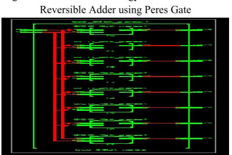
View technology schematic of 32-bit reversible adder using Peres gate is shown in figure 3.1.1. In this figure A and B is the two input of the BCD adder with 32-bit word length, sum is the output of
BCD adder with 5-bit word length.
Figure 3.1.1: View Technology Schematic of 32-bit Reversible Adder using Peres Gate
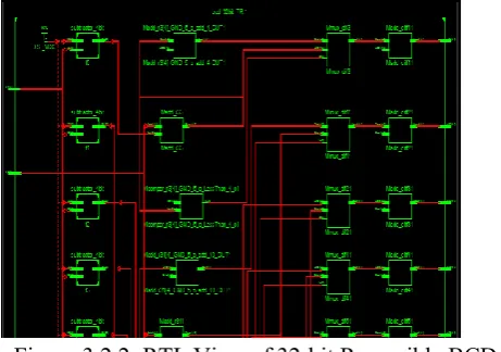
Figure 3.1.2: RTL View of 32-bit Reversible BCD Adder using Peres Gate
RTL view of 32-bit reversible adder using Peres gate is shown in figure 3.1.2. Device utilization summary of 32-bit reversible BCD adder using Peres gate is shown in figure 3.1.3 and timing summary of the 32-bit reversible BCD adder using Peres gate is shown in figure 3.1.4.
Figure 3.1.3: Device Utilization Summary of 4-bit Reversible BCD Adder using Peres Gate
Figure 3.1.4: Timing Summary of 4-bit Reversible BCD Adder using Peres Gate
Figure 3.1.5: Output Waveform of 32-bit Reversible BCD Adder using Peres Gate
B. 32-bit Reversible BCD Subtractor
Figure 3.5.1: View Technology Schematic of 32-bit Reversible Adder/Subtractor using DKG Gate
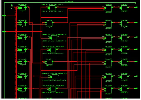
Figure 3.2.2: RTL View of 32-bit Reversible BCD Subtractor using TR Gate
RTL view of 32-bit reversible BCD subtractor using TR gate is show in figure 3.2.2. Device utilization summary of 32-bit reversible BCD subtractor using TR gate is show in figure 3.2.3 and timing summary of the 32-bit reversible BCD subtractor using TR gate is shown in figure 3.2.4.
Figure 3.2.4: Timing Summary of 4-bit Reversible BCD Subtractor using TR Gate
Figure 3.2.5: Output Waveform of 32-bit Reversible BCD Subtractor using TR Gate
C. 64-bit Reversible BCD Adder
View technology schematic of 64-bit reversible adder using Peres gate is shown in figure 5.21. In this figure A and B is the two input of the BCD adder with 64-bit word length, sum is the output of the BCD adder with 5-bit word length.
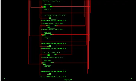
Figure 3.3.2: RTL View of 64-bit Reversible BCD Adder using Peres Gate
RTL view of 64-bit reversible adder using Peres gate is shown in figure 3.3.2. Device utilization summary of 64-bit reversible BCD adder using Peres gate is show in figure 3.3.3 and timing summary of the 64-bit reversible BCD adder using Peres gate is shown in figure 3.3.4.
Figure 3.3.3: Device Utilization Summary of 64-bit Reversible BCD Adder using Peres Gate
Figure 3.3.4: Timing Summary of 64-bit Reversible BCD Adder using Peres Gate
Figure 3.3.5: Output Waveform of 64-bit Reversible BCD Adder using Peres Gate
D. 64-bit Reversible BCD Subtractor
View technology schematic of 64-bit reversible subtractor using TR gate is shown in figure 3.4.1. In this figure A and B is the two input of the BCD subtractor with 5-bit word length, B2 is the output of the BCD adder with 5-bit word length.
Figure 3.4.2: RTL View of 64-bit Reversible BCD Subtractor using TR Gate
RTL view of 64-bit reversible BCD subtractor using TR gate is show in figure 3.4.2. Device utilization summary of 64-bit reversible BCD subtractor using TR gate is show in figure 3.4.3 and timing summary of the 64-bit reversible BCD subtractor using TR gate is show in figure 3.4.4.
Figure 3.4.3: Device Utilization Summary of 64-bit Reversible Subtractor using TR Gate
Figure 3.4.4 : Timing Summary of 64-bit Reversible
Figure 3.4.5: Output Waveform of 64-bit Reversible BCD Subtractor using TR Gate
E. 32-bit Reversible BCD Adder/Subtractor using
DKG Gate
View technology schematic of 32-bit reversible adder/subtractor using DKG gate is shown in figure 3.5.1. In this figure A and B is the two input of the BCD adder/subtractor with 4-bit word length, B2 is the output of the BCD adder with 5-bit word length.
Figure 3.5.1: View Technology Schematic of 32-bit Reversible Adder/Subtractor using DKG Gate
3.5.3. and timing summary of the 32-bit reversible BCD adder/subtractor using DKG gate is shown in figure 3.5.4.
Figure 3.5.3: Device Utilization Summary of 32-bit Reversible Adder/Subtractor using DKG Gate
Figure 3.5.4: Timing Summary of 32-bit Reversible BCD Adder/Subtractor using DKG Gate
Figure 3.5.5: Output Waveform of 32-bit Reversible BCD Adder/Subtractor using DKG Gate
F. 64-bit Reversible BCD Adder/Subtractor using
DKG Gate
View technology schematic of 64-bit reversible adder/subtractor using DKG gate is shown in figure 3.6.1. In this figure A and B is the two input of the BCD adder/subtractor with 4-bit word length, B2 is the output of the BCD adder with 5-bit word ength.
Figure 3.6.1: View Technology Schematic of 64-bit Reversible Adder/Subtractor using DKG Gate
Figure 3.6.2.: RTL View of 64-bit Reversible BCD Adder/Subtractor using DKG Gate
RTL view of 64-bit reversible BCD adder/subtractor using DKG gate is show in figure 3.6.2. Device utilization summary of 64-bit reversible BCD adder/subtractor using DKG gate is showin figure 3.6.3 and timing summary of the 64-bit reversible BCD adder/subtractor using DKG gate is shown in figure 3.6.4.
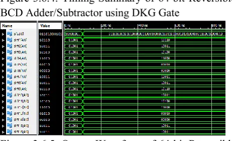
Figure 3.6.4: Timing Summary of 64-bit Reversible BCD Adder/Subtractor using DKG Gate
Figure 3.6.5: Output Waveform of 64-bit Reversible BCD Adder/Subtractor using DKG Gate
IV.
RESULTS AND CONCLUSION
In this paper, the design of 32-bit BCD add- subtract unit have been implemented using reversible logic gates. BCD arithmetic units are speedy manipulation with reduced area. 32-bit subtraction unit have been design using 4-bit nine’s complement and 4- bit BCD addition unit. The proposed module has wide range of application in digital signal processing. The estimated parameters for reversible 32-bit BCD addition unit is about 416 garbage values with the critical path delay of 17.420 ns; reversible 32-bit BCD subtraction module is about 240 garbage values with the critical path delay of about 17.420 ns.
V.
REFERENCES
[1]. Vivechana Dubey and Ravimohan Sairam, “An Arithmetic and Logic Unit Optimized for Area and power”, 978-1-4799-4910-6/14 $31.00 © 2014 IEEE DOI 10.1109/ACCT.2014.70.
4799-4910-6/14 $31.00 © 2012 IEEE DOI 10.1109/ACCT.2014.70.
[3]. Nidhi Gupta, “Thermal Analysis of Energy Efficient Clock Gated Arithmetic Logic Unit on FPGA”, 978-1-4799-4190-2/14/$31.00 ©2014 IEEE.
[4]. Matthew Morrison and Nagarajan Ranganathan, “Design of a Reversible ALU based on Novel Programmable Reversible Logic Gate Structures”, 2013 IEEE Computer Society Annual Symposium on VLSI.
[5]. LekshmiViswanath and Ponni.M, “Design and Analysis of 16 Bit Reversible ALU”, ISSN: 2278-0661 Volume 1, Issue 1 (May-June 2012), PP 46-53
[6]. Akanksha Dixit and VinodKapse, “Arithmetic & Logic Unit (ALU) Design using Reversible Control Unit”, International Journal of Engineering and Innovative Technology (IJEIT) Volume 1, Issue 6, June 2012.
[7]. Mr. Abhishek Gupta, Mr. UtsavMalviya and Prof. VinodKapse, “Design of Speed, Energy and Power Efficient Reversible Logic Based Vedic ALU for Digital Processors”, 2012 IEEE Computer Society Annual Symposium on VLSI.
[9]. H. Thapliyal and N. Ranganathan, "Design of Reversible Sequential Circuits Optimizing Quantum Cost, Delay, and Garbage Outputs," ACM Journal on Emerging Technologies in Computing Systems, 2010.
Physics A: Mathematical and Theoretical. 43 (2010).
[13]. H. R. Bhagyalakshmi, M. K. Venkatesha, “An improved design of a multiplier using reversible logic gates”, International Journal of Engineering Science and Technology, Vol. 2(8), pp: 3838-3845, 2010.
[14]. Lihui Ni, Zhijin Guan, and Wenying Zhu, “A General Method of Constructing the Reversible Full-Adder”, Third International Symposium on Intelligent Information Technology and Security Informatics, pp.109-113, 2010.
[15]. H. Thapliyal and N. Ranganathan, "Design of Efficient Reversible Binary Subtractors Based on A New Reversible Gate," Proc. of the IEEE Computer Society Annual Symposium on VLSI, 2009, pp 229-234.