CSEIT1725202 | Received : 10 Oct 2017 | Accepted : 25 Oct 2017 | September-October-2017 [(2)5: 878-887]
International Journal of Scientific Research in Computer Science, Engineering and Information Technology © 2017 IJSRCSEIT | Volume 2 | Issue 5 | ISSN : 2456-3307
878
Network Simulator Version 2 for VANET
Venkatatamangarao Nampally
*1, Dr. M. Raghavender Sharma
2, Dr. K. R. Balaji
3*1Department of Computer Science, University College of Science, Osmania University, Hyderabad, Telangana, India 2Department of Statistics, University College of Science, Osmania University, Saifabad, Hyderabad, Telangana, India 3Department of Network Systems and Information Technology, University of Madras, Guindy Campus, Chennai, Tamil Nadu, India
ABSTRACT
A Network simulator is used in different areas such as academic research, industrial development, and Quality Assurance (QA) to design, simulate, verify, and analyze the performance of different networks protocols. Network simulators are also particularly useful in allowing the network designers to test new networking protocols or to change the existing protocols in a controlled and reproducible manner. NS2 is often growing to include new protocols. NS2 is an object-oriented simulator, written in C++, with an OTcl interpreter as a frontend. In this paper we discuss NS2 simulator in detail.
Keywords : NS2, TCL, C++, NAM, Xgraph, and Ubuntu OS.
I.
INTRODUCTION
Simulation is a very important modern technology. Computer simulation can be used to assist the modeling and analysis in many natural systems. NS (Version 2) is an open source network simulation tool. It is an object oriented, discrete event driven simulator written in C++ and Otcl. The primary use of NS is in network research to simulate various types of wired/wireless local and wide area networks; to implement network protocols such as TCP and UPD, traffic source behaviour such as FTP, Telnet, Web, CBR and VBR, router queue management mechanism such as Drop Tail, RED and CBQ, routing algorithms such as Dijkstra, and many more. Ns2 is written in C++ and Otcl to separate the control and data path implementations. The simulator supports a class hierarchy in C++ (the compiled hierarchy) and a corresponding hierarchy within the Otcl interpreter (interpreted hierarchy). The reason why ns2 uses two languages is that different tasks have different requirements: For example simulation of protocols requires efficient manipulation of bytes and packet headers making the run-time speed very important. On the other hand, in network studies where the aim
Volume 2 | Issue 5 | September-October-2017 | www.ijsrcseit.com | UGC Approved Journal [ Journal No : 64718 ] implementations for network nodes, links between
nodes, routing algorithms, some transport level protocols (especially UDP and many different variants of TCP) and some traffic generators. The simulator can be extended by adding functionality to these objects. NS2 also contains some useful utilities include like Tcl debugger, simulation scenario generator and simulation topology generator. Tcl debugger is used to debug Tcl scripts and it might become necessary if one is using large scripts to control a simulation. Tcl-debug is not however installed automatically with NS2 but it can be installed later. One drawback of using Tcl-debug is that it is dependent on used Tcl version and NS2 version. For topology generation there are four choices: NTG, RTG, GT-ITM and TIERS packages. With these topology generators, one can create large network topologies without the need to define the whole topology by hand. Simulation scenario generator can be used to create traffic between nodes. When simulating wireless networks, the scenario generator can be used to generate files that define the movement of nodes.
Figure 1. Simplified user‟s view of NS2
A. Features of NS2
NS2 are discrete simulation events aimed in networks researches. It provides support for simulation of Transmission Control Protocol (TCP) and it is one of the core protocols of the Internet protocol suite. TCP is one of the two original components of the suite, complementing the Internet Protocol (IP), and therefore the entire suite is commonly referred to as TCP/IP, routing, and multicast protocols over all networks including wired and wireless networks. NS2 can be employed in most UNIX and it is a multitasking, multiuser computer operating systems and windows (XP, VESTA and 7). Most of the NS2 code processing is in C++ language. It uses Terminal Command Language (TCl) as its scripting language.
B. Programming Languages
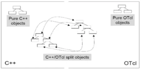
The reason for having two programming languages is to have an easy to use, yet fast and powerful simulator. C++ forms an efficient class hierarchy core of NS2 that takes care of handling packets, headers and algorithms. Object Tcl, or OTcl, is also an object oriented programming language utilized in NS2 for network scenario creation, allowing fast modifications to scenario scripts. OTcl and C++ interact with each other through Tcl/C++ interface calledTcl/C++. Tcl/Otcl is a language with very simple syntaxes that allows easy integration with other languages. Tcl was created by JohnOusterhout. The characteristics of these languages are :
• It allows a fast development. • It provides a graphic interface. • It is compatible with many platforms. • It is flexible for integration.
• It is a scripting language.
Tcl in ns-2 enables full control over simulation setup, configuration, and occasional actions (e.g. creating new TCPflows). It is a language that compromise between speed and abstraction level offered to the user. In the scenario of this project the Tcl language is used to design the network (set parameters, node configurations, and topology, Connection between nodes, transfer packages and simulation time).Further more, C++ language is used for the security package (encryption /decryption).
Figure 2. C++ and Tcl communication
Volume 2 | Issue 5 | September-October-2017 | www.ijsrcseit.com | UGC Approved Journal [ Journal No : 64718 ]
II.
RELATED WORK
In the research area of computer and communications networks, simulation is a useful technique since the behaviour of a network can be modelled by calculating the interaction between the different network components (they can be end-host or network entities such as routers, physical links or packets) using mathematical formulas. .In order to understand and simulate in NS2, we have to understand the syntax and some basic commands of the TCL language which is used by ns2 software given by some literature survey. It is important to understand how TCL works before moving to the part that deals with the creation of the actual simulation scenario.
A. OTCL Basics
1) Assigning Values to Variables: In tcl, values can be stored to variables and these values can be further used in commands: argument to another command, which in turn assigns a value to the variable b. The “$” sign is used to obtain a value contained in a variable and square brackets are an indication of a command substitution.
2) Procedures: One can define new procedures with the proc command. The first argument to proc is the name of the procedure and the second argument contains the list of the argument names to that procedure. For instance a procedure that calculates the sum of two numbers can be defined as follows:
proc sum {a b} {
#here the procedure is called again expr $x * [factorial [expr $x-1]] }
It is also possible to give an empty string as an argument list. However, in this case the variables that are used by the procedure have to be defined as global. For instance:
set testfile [open test.dat r]
The first line of the file can be stored to a list with a command:
gets $testfile list
Now it is possible to obtain the elements of the list with commands (numbering of elements starts from 0):
set first [lindex $list 0] set second [lindex $list 1]
Similarly, a file can be written with a puts command:
set testfile [open test.dat w] puts $testfile “testi”
4) Calling Sub processes: The command exec creates a sub process and waits for it to complete. The use of exec is similar to giving a command line to a shell program. For instance, to remove a file:
exec rm $testfile
The exec command is particularly useful when one wants to call a tcl-script from within another tclscript. For instance, in order to run the tcl-script example.tcl multiple times with the value of the parameter “test” ranging from 1 to 10, one can type the following lines to another tcl-script:
for {set ind 1} {$ind <= 10} {incr ind} { set test $ind
exec ns example.tcl test }
B. Simulation Parameters
When a new simulation object is created in tcl, the initialization procedure performs the following operations:
Volume 2 | Issue 5 | September-October-2017 | www.ijsrcseit.com | UGC Approved Journal [ Journal No : 64718 ] •create a scheduler (defaults to a calendar scheduler)
•create a “null agent” (a discard sink used in various places)
1) Creating topology: To be able to run a simulation scenario, a network topology must first be created. In ns2, the topology consists of a collection of nodes and links. Before the topology can be set up, a new simulator object must be created at the beginning of the script with the command:
set ns [new Simulator]
The simulator object has member functions that enable creating the nodes and the links, connecting agents etc. All these basic functions can be found from the class Simulator. When using functions belonging to this class, the command begins with “$ns”, since ns was defined to be a handle to the Simulator object.
2) Creating nodes: New node objects can be created with the command:
set n0 [$ns node] set n1 [$ns node] set n2 [$ns node] set n3 [$ns node]
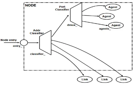
The member function of the Simulator class, called “node” creates four nodes and assigns them to the handles n0, n1, n2 and n3. These handles can later be used when referring to the nodes. If the node is not a router but an end system, traffic agents (TCP, UDP etc.) and traffic sources (FTP,CBR etc.) must be set up, i.e, sources need to be attached to the agents and the agents to the nodes, respectively.
Figure 3.Structure of unicast node
3) Agents, Applications and Traffic Sources: The
most common agents used in ns2 are UDP and TCP agents. In case of a TCP agent, several types are available. The most common agent types are:
Agent/TCP – a Tahoe TCP sender Agent/TCP/Reno – a Reno TCP sender
Agent/TCP/Sack1 – TCP with selective acknowledgement
The most common applications and traffic sources provided by ns2 are:
Application/FTP – produces bulk data that TCP will send
Application/Traffic/CBR – generates packets with a constant bit rate
Application/Traffic/Exponential – during off-periods, no traffic is sent. During on-periods, packets are generated with a constant rate. The length of both on and off-periods is exponentially distributed.
Application/Traffic/Trace – Traffic is generated from a trace file, where the sizes and inter arrival times of the packets are defined.
In addition to these ready-made applications, it is possible to generate traffic by using the methods provided by the class Agent. For example, if one wants to send data over UDP, the method
send (int nbytes)
can be used at the tcl-level provided that the udp-agent is first configured and attached to some node.
Below is a complete example of how to create a CBR traffic source using UDP as transport protocol and attach it to node n0:
set udp0 [new Agent/UDP] $ns attach-agent $n0 $udp0
set cbr0 [new Application/Traffic/CBR] $cbr0 attach-agent $udp0
Volume 2 | Issue 5 | September-October-2017 | www.ijsrcseit.com | UGC Approved Journal [ Journal No : 64718 ] An FTP application using TCP as a transport protocol
can be created and attached to node n1 in much the same way:
set tcp1 [new Agent/TCP] $ns attach-agent $n1 $tcp1 set ftp1 [new Application/FTP] $ftp1 attach-agent $tcp1 $tcp1 set packet_size_ 1000
The UDP and TCP classes are both child-classes of the class Agent. With the expressions [new Agent/TCP] and [new Agent/UDP] the properties of these classes can be combined to the new objects udp0 and tcp1. These objects are then attached to nodes n0 and n1. Next, the application is defined and attached to the transport protocol. Finally, the configuration parameters of the traffic source are set. The default value is 0, meaning that no randomness is added. The TCP agent does not generate any application data on its own: instead, the simulation user can connect any traffic generation module to the TCP agent to generate data. Two applications are commonly used for TCP: FTP and telnet. FTP represents a bulk data transfer of large size, and telnet chooses its transfer sizes randomly from tcplib. There are two major types of TCP agents : one-way agents and a two-way agent.
One-way agents are further subdivided into a set of TCP senders (which obey different congestion and error control techniques) and receivers (sinks). The two-way agent is symmetric in the sense that it represents both a sender and receiver. It is still under development.
4) Traffic Sinks: If the information flows are to be terminated without processing, the udp and tcp sources have to be connected with traffic sinks. A TCP sink is defined in the class Agent/TCPSink and an UDP sink is defined in the class Agent/Null. A UDP sink can be attached to n2 and connected with udp0 in the following way:
set null [new Agent/Null] $ns attach-agent $n2 $null $ns connect $udp0 $null
A standard TCP sink that creates one acknowledgement per a received packet can be attached to n3 and connected with tcp1 with the commands:
set sink [new Agent/Sink] $ns attach-agent $n3 $sink $ns connect $tcp1 $sink
For example, to create a standard TCP connection between n1 and n3 with a class ID of 1:
$ns create-connection TCP $n1 TCPSink $n3 1
One can very easily create several tcp-connections by using this command inside a for-loop.
5) Links: Links are required to complete the topology. In ns2, the output queue of a node is implemented as part of the link, so when creating links the user also has to define the queue-type.
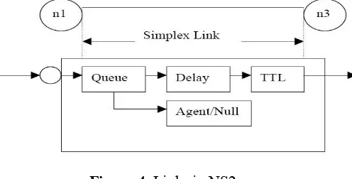
Figure 4. Links in NS2
Figure shows the construction of a simplex link in ns2. If a duplex-link is created, two simplex links will be created, one for each direction. In the link, packet is first enqueued at the queue. After this, it is either dropped, passed to the Null Agent and freed there, or dequeued and passed to the Delay object which simulates the link delay. Finally, the TTL (time to live) value is calculated and updated. Links can be created with the following command:
$ns duplex/simplex-link endpoint1 endpoint2 bandwidth delay queue-type
For example, to create a duplex-link with DropTail queue management between n0 and n2:
$ns duplex-link $n0 $n2 15Mb 10ms DropTail
Creating a simplex-link with RED queue management between n1 and n3:
$ns simplex-link $n1 $n3 10Mb 5ms RED
Volume 2 | Issue 5 | September-October-2017 | www.ijsrcseit.com | UGC Approved Journal [ Journal No : 64718 ]
Figure 5. Composite construction of a unidirectional link
C. Tracing and Monitoring
In order to be able to calculate the results from the simulations, the data has to be collected somehow. NS2 supports two primary monitoring capabilities: traces and monitors. The traces enable recording of packets whenever an event such as packet drop or arrival occurs in a queue or a link. The monitors provide a means for collecting quantities, such as number of packet drops or number of arrived packets in the queue. The monitor can be used to collect these quantities for all packets or just for a specified flow (a flow monitor).
1) Traces : All events from the simulation can be recorded to a file with the following commands:
set trace_all [open all.dat w] $ns trace-all $trace_all $ns flush-trace
close $trace_all
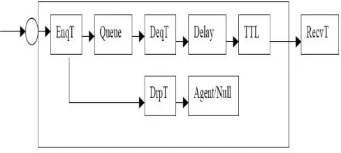
First, the output file is opened and a handle is attached to it. Then the events are recorded to the file specified by the handle. Finally, at the end of the simulation the trace buffer has to be flushed and the file has to be closed. This is usually done with a separate finish procedure. If links are created after these commands, additional objects for tracing (EnqT, DeqT, DrpT and RecvT) will be inserted into them.
Figure 6.link in NS2 when tracing enabled
These new objects will then write to a trace file whenever they receive a packet. The format of the trace file is following:
+ 1.84375 0 2 cbr 210 --- 0 0.0 3.1 225 610 - 1.84375 0 2 cbr 210 --- 0 0.0 3.1 225 610 r 1.84471 2 1 cbr 210 --- 1 3.0 1.0 195 600 r 1.84566 2 0 ack 40 --- 2 3.2 0.1 82 602 + 1.84566 0 2 tcp 1000 --- 2 0.1 3.2 102 611 - 1.84566 0 2 tcp 1000 --- 2 0.1 3.2 102 611
+ : enqueue - : dequeue d : drop r : receive
The fields in the trace file are: type of the event, simulation time when the event occurred, source and destination nodes, packet type (protocol, action or traffic source), packet size, flags, flow id, source and destination addresses, sequence number and packet id. In addition to tracing all events of the simulation, it is also possible to create a trace object between a particular source and a destination with the command:
$ns create-trace <type> <file> <src> <dest>
where the type can be, for instance,
Enque – a packet arrival (for instance at a queue) Deque – a packet departure (for instance at a queue) Drop – packet drop
Recv – packet receive at the destination
Tracing all events from a simulation to a specific file and then calculating the desired quantities from this file for instance by using perl or awk and Matlab is an easy way and suitable when the topology is relatively simple and the number of sources is limited. However, with complex topologies and many sources this way of collecting data can become too slow. The trace files will also consume a significant amount of disk space.
2) Monitors: With a queue monitor it is possible to track the statistics of arrivals, departures and drops in either bytes or packets. Optionally the queue monitor can also keep an integral of the queue size over time.
For instance, if there is a link between nodes n0 and n1, the queue monitor can be set up as follows:
set qmon0 [$ns monitor-queue $n0 $n1]
Volume 2 | Issue 5 | September-October-2017 | www.ijsrcseit.com | UGC Approved Journal [ Journal No : 64718 ]
set parr [$qmon0 set parrivals_] set bdrop [$qmon0 set bdrops_]
Besides assigning a value to a variable the set command can also be used to get the value of a variable. For example here the set command is used to get the value of the variable “parrivals” defined in the queue monitor class. A flow monitor is similar to the queue monitor but it keeps track of the statistics for a flow rather than for aggregated traffic. A classifier first determines which flow the packet belongs to and then passes the packet to the flow monitor. The flow monitor can be created and attached to a particular link with the commands:
set fmon [$ns makeflowmon Fid]
$ns attach-fmon [$ns link $n1 $n3] $fmon
Notice that since these commands are related to the creation of the flow-monitor, the commands are defined in the Simulator class, not in the Flowmonitor class. The variables and commands in the Flowmonitor class can be used after the monitor is created and attached to a link. For instance, to dump the contents of the flowmonitor (all flows):
$fmon dump
If you want to track the statistics for a particular flow, a classifier must be defined so that it selects the flow based on its flow id, which could be for instance 1:
set fclassifier [$fmon classifier]
set flow [$fclassifier lookup auto 0 0 1]
D. Controlling of Simulation
After the simulation topology is created, agents are configured etc., the start and stop of the simulation and other events have to be scheduled. The simulation can be started and stopped with the commands:
$ns at $simtime “finish” $ns run
The first command schedules the procedure finish at the end of the simulation, and the second command actually starts the simulation. The finish procedure has to be defined to flush the trace buffer, close the trace files and terminate the program with the exit routine. It can optionally start NAM (a graphical network animator), post process information and plot this information. The finish procedure has to contain at least the following elements:
proc finish {} {
Other events, such as the starting or stopping times of the clients can be scheduled in the following way:
$ns at 0.0 “cbr0 start” $ns at 50.0 “ftp1start” $ns at $simtime “cbr0 stop” $ns at $simtime “ftp1 stop”
If you have defined your own procedures, you can also schedule the procedure to start for example every 5 seconds in the following way:
proc example {} { global ns
set interval 5 ….
…
$ns at [expr $now + $interval] “example” }
III.
METHODOLOGY
A. Extending NS: Creating a new Agent
One can extend NS by adding new protocols. One node will send n user defined number packets, one at a time at regular intervals, to another node which will return the packet immediately. For each packet the sender will then calculate the round trip time.
1) Header File : First, we have to create a header file
“myPing.h” in which we will define the data structure
for the myPing packet header. The char „ret‟ is going to be set to '0' if the packet is on its way from the sender to the node which is being pinged, while it is going to be set to '1' on its way back. The double 'send_time' is a time stamp that is set on the packet when it is sent. This time is later used by the sender to calculate the round-trip-time. The rest of the part of program codes of the header are used to access the packet header from any packet reference.
B. Necessary Changes to NS2
Volume 2 | Issue 5 | September-October-2017 | www.ijsrcseit.com | UGC Approved Journal [ Journal No : 64718 ]
Figure 7. Directory structure
1) Edit packet.h file: We need a new packet type for our MyPing agent, therefore the first step is to modify the “$NS/common/packet.h” file (assuming that the $NS environment variable points the …./ns-allinone-2.31/ns-2.31 location). There you can find the definitions for the packet protocol IDs (i.e. PT_TCP, PT_TELNET, etc.). Add a new definition for PT_PING there. In my edited version of packet.h, the last few lines of enum packet_t{} looks like the following code (it might look a bit different in different NS releases). You also have to edit the p_info() in the same file to include "MyPing".
2) Edit ns-packet.tcl file: Now in “
$NS/tcl/lib/ns-packet.tcl” file search for the part foreach prot { .. }.
Within this part add an entry for MyPing.
3) Edit ns-default.tcl: The “$NS/tcl/lib/ns-default.tcl” file is the file where all default values for the Tcl objects are defined. Insert the following line to set the default packet size, packet number and wait interval for Agent/MyPing.
Agent/MyPing set packetSize_ 200 Agent/MyPing set num_packets_ 3 Agent/MyPing set wait_interval_ .001
4) Edit Makefile.in: The last change is a change that has to be applied to the “$NS/Makefile.in”. You have to add the file “myPing.o” to the list of object files for ns.
C. Recompile NS
After the changes are done in the NS files we need to recompile the NS simulator. To do so use the following command:
droy@aggarpc3:~$ cd $NS droy@aggarpc3:ns-2.31$ pwd /usr/share/ns-allinone-2.31/ns-2.31
droy@aggarpc3:ns-2.31$ sudo ./configure
droy@aggarpc3:ns-2.31$ sudo make
After recompiling the NS simulator we can use our MyPing agent in our simulations. Following code is simple tcl program that uses the MyPing agent.
D. Notepad++
Notepad++ is a text editor and source code editor for use with Microsoft Windows. It supports tabbed editing, which allows working with multiple open files in a single window. The project's name comes from the C increment operator. Notepad++ is distributed as free software. since 2015 Notepad++ has been hosted on GitHub. Notepad++ uses the Scintilla editor component.
Figure 8.Notepad++ text editor
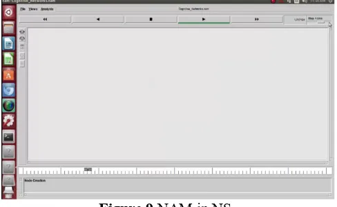
E. NAM (Network AniMator)
NAM is a Tcl/TK based animation tool for viewing network simulation traces and real world packet traces. It supports topology layout, packet level animation, and various data inspection tools.
Volume 2 | Issue 5 | September-October-2017 | www.ijsrcseit.com | UGC Approved Journal [ Journal No : 64718 ]
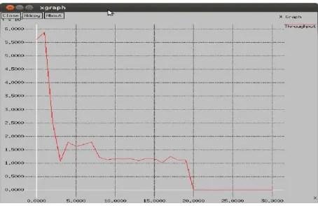
F. Xgraph
One part of the ns-allinone package is 'xgraph', a plotting program which can be used to create graphic representations of simulation results.
Figure 10. Xgraph in NS
IV.
SIMULATION RESULTS
it is concluded that NS2 is most common used simulator for obtaining accurate results. When we crated VANET environment in NS2 simulator, we got some results given below. Not only these results but also we can get other results in the form of Xgraph.
Figure 11.
Simple example in NS
Figure 12.
NS2 graph specimen
V.
CONCLUSION
We have learnt a lot about NS-2 and simulation scenarios in ns2 and it is also a good experience to work on ubuntu. In conclusion, we found out that network simulator (NS2), is used as a tool to design the result of the simulation are transfer information secure between nodes.
VI.
ACKNOWLEDGMENT
I will be thankful forever to the LORD BAJARANGBALI for his boundless blessings showered on me. I am very grateful and express my heartfelt countless Namaste to most respectable and my M.Phil. Guide and supervisor who are Dr. S. Ananthi madam ji,B.E.,M.Tech.(IISC),Ph.D., Associate Professor, Department of Network Systems and Information Technology, University of Madras, Guindy Campus, Chennai for their constant support, invaluable and inspiring guidance to the progress of my paper work. Without madam ji, and Sir K. Padmanabhan inspiration, definitely this paper work would not have been possible.
Volume 2 | Issue 5 | September-October-2017 | www.ijsrcseit.com | UGC Approved Journal [ Journal No : 64718 ]
VII.
REFERENCES
[1].
Bidgoli H., "Handbook of Information Security", john Wiley & Sons, Inc. Volume 1, 2006.[2].
Andrea Goldsmith, Wireless Communications, Cambridge UniversityPress, September 2005, ISBN13: 9780521837163.[3].
Altman, E.; Jiménez, T. (2003). NS Simulator for beginners [Online]. Available: citeseer.ist.psu.edu/altman03ns.html[4].
Greis, Marc. Tutorial for the Network Simulator "ns"[Online]. Available:
http://www.isi.edu/nsnam/ns/tutorial/
[5].
L. Breslau et al. Advances in network simulation. IEEE Computer, 33(5):59-67, May 2000.[6].
S. McCanne and S. Floyd. ns Network Simulator. http://www.isi.edu/nsnam/ns/.[7].
T. Issariyakul , and E. Hossain , "Introduction to Network Simulator NS2," Springer, Oct. 2008, ISBN: 978-0-387-71759-3.[8].
[REAL] REAL 5.0 simulator overview, http://www.cs.cornell.edu/skeshav/real/overview.ht mlAUTHORS
Dr. M. Raghavender Sharma ([email protected]) pursed Bachelor of Science in Mathematics, Master of Science in Statistics, and achieved Doctoral Degree in Statistics, all degrees from Osmania University, Hyderabad, Telangana, India, and currently he is working as an Assistant Professor and Head of Department, Department of Statistics at University College of Science, Saifabad, Osmania University, Hyderabad, Telangana, India. He is supervising many Ph. D.‟s. He has excellent teaching track record with 25 years teaching experience.
Dr. K. R. Balaji
([email protected]) has completed M.sc, M.Phil., Ph.D. currently he is working at University of Madras, Guindy Campus, Chennai, Tamil Nadu, India in the department of network systems & information technology. He is the author of several papers. He has presented papers at the National and Interactional conferences relating to convolutional encoding and fuzzy based decoding as alternative to Viterbi‟s decoder. His special interests are in Telecommunication Engineering and Mobile wireless sensor networks