Design and Prototyping of a
Human-Computer Interface for a Desktop
Tele-classroom Conference Application
Author: Marcel van Bergen
Date: August 30, 2007
University: University of Twente, Netherlands
Department Electrical Engineering, Mathematics & Computer Science
Architectures and Services of Network Applications
Graduation Committee: dr.ir. I.A. Widya
Table of contents
1 PROBLEM DEFINITION ... 6
1.1 SUMMARY... 6
1.2 BACKGROUND... 6
1.2.1 General ... 6
1.2.2 Human Computer Interface ... 7
1.2.3 The Desktop Tele-classroom Conference system ... 7
1.2.4 Lecture ... 7
1.3 MORE DETAILED BACKGROUND AND FIRST REQUIREMENTS... 7
1.3.1 Use of different classroom descriptions... 7
1.3.2 Description of a real, face-to-face classroom... 8
1.3.3 Requirements for a DTC system... 8
1.3.4 Description of a DTC system ... 9
1.3.5 Differences with existing teleconference systems... 10
1.4 GOAL... 10
1.5 RESEARCH QUESTIONS... 11
1.6 ORGANISATION OF THIS REPORT... 11
2 LITERATURE STUDY ... 13
2.1 SUMMARY... 13
2.2 WHAT IS RELEVANT? ... 13
2.3 WHERE TO SEARCH? ... 14
2.4 EXAMINED LITERATURE... 14
2.4.1 Finding a design method for HCI’s ... 14
2.4.2 Additional constraints ... 15
2.4.3 Results ... 15
2.5 CONSTRAINTS... 17
2.5.1 Hardware constraints ... 17
2.5.2 Software constraints... 17
2.5.3 Functional constraints ... 17
3 USER REQUIREMENTS ... 18
3.1 INTRODUCTION... 18
3.2 THE 2-STEPS APPROACH... 18
3.3 DTC APPLICATION ORIENTED HCI-REQUIREMENTS... 19
3.3.1 General description of the desktop Tele-classroom Conference (DTC) system... 19
3.3.2 Actors, roles and scenarios: a description... 20
3.3.3 Actors, roles and scenario’s in the desktop Tele-classroom Conference system ... 20
3.3.4 Detailed lecture scenario for the desktop Tele-classroom Conference ... 21
3.3.5 Task analysis for the lecture scenario... 21
3.3.6 Definition of “Floor”... 22
3.3.7 Entity-Relationship diagrams ... 22
3.4 GENERIC DESKTOP TELECONFERENCE MODEL ORIENTED HCI-REQUIREMENTS... 25
3.4.1 A generic Desktop Teleconference model ... 25
3.4.2 Detailed description of the generic desktop teleconference model... 25
3.4.3 Description of the scenario, the actors and their roles within a generic Teleconference model. 25 3.4.4 Detailed lecture scenario for a conference system using a generic desktop Teleconference model26 3.4.5 Rights that belong to roles ... 26
3.4.6 Task analyses for a conference system using a generic Teleconference model... 27
3.4.7 Entity-Relationship diagrams ... 27
3.5 THE MAPPING OF THE DTC SYSTEM TO A SYSTEM USING A GENERIC DESKTOP TELECONFERENCE MODEL33 3.5.1 The mapping of the systems ... 33
3.5.2 The mapping of the actors and roles... 35
4 HCI DESIGN FOR THE DTC SYSTEM ... 36
4.1 INTRODUCTION... 36
4.2 GENERAL OVERVIEW OF THE FUNCTIONALITY OF THE HCI FROM THE DTC SYSTEM... 36
4.3 THE MAPPING FROM TASKS TO FUNCTIONALITY... 38
4.4 THE DIFFERENT HCI MAIN-ELEMENTS OF THE DTC APPLICATION... 38
4.4.1 Division into HCI-views... 38
4.4.2 The HCI-views ... 38
4.4.3 Relation between the HCI views ... 39
4.5 THE FULLY DESIGNED HCI-VIEWS WITHIN THE DTC SYSTEM... 40
4.5.1 Considerations for all HCI-view descriptions ... 40
4.5.2 A HCI view for entering a groupmeeting... 40
4.5.3 A HCI view for inspecting / modifying / requesting floors... 41
4.5.4 A HCI view for local media control ... 48
4.5.5 HCI views for adapting and using floors ... 51
4.6 SUGGESTIONS FOR A NEXT DESIGN-CYCLE (HALF-IMPLEMENTATIONS, MOCK-UPS AND PROPOSALS) .... 52
4.6.1 A HCI view for inspecting, modifying and requesting floors... 53
4.6.2 A HCI view for inspecting and modifying the groupmeeting ... 54
4.6.3 A HCI view for local media control ... 58
4.6.4 HCI views for adapting and using floors ... 58
4.7 FLOOR MANAGEMENT... 60
4.7.1 Introduction ... 60
4.7.2 An extra floor management layer... 61
4.7.3 Floor information... 62
4.7.4 The management of floors... 63
5 IMPLEMENTATION ... 68
5.1 INTRODUCTION... 68
5.2 IMPLEMENTATION REQUIREMENTS... 68
5.3 MAIN ARCHITECTURE OF THE DTC SYSTEM... 69
5.3.1 Division into layers ... 69
5.3.2 Subdivision into modules ... 70
5.4 THE ARCHITECTURE OF THE LAYERS... 70
5.4.1 The HCI layer ... 70
5.4.2 The floor management layer ... 72
5.4.3 Session-independent-layer ... 73
5.4.4 Operating-System Independent layer... 73
5.5 THE MODULES... 75
5.5.1 The initialisation module (Main) ... 75
5.5.2 The start-up HCI-view ... 75
5.5.3 The floor management HCI-view... 77
5.5.4 The floor status HCI-view ... 78
5.5.5 The local media control HCI-view... 79
5.5.6 The text-floor HCI-view ... 79
5.5.7 Refuse request popup. ... 79
5.5.8 Floor request popup... 80
5.5.9 Whiteboard mock-up HCI ... 80
5.5.10 The groupmeeting control mock-up HCI ... 81
5.5.11 External module: pictures of faces... 81
5.5.12 The user database module ... 81
5.5.13 Request / grants module... 82
5.5.14 The floor database module... 82
5.5.15 The floor-windows module... 82
5.5.16 The floor control module ... 82
5.5.17 The floor use module... 82
5.5.18 The floor definition module... 83
5.5.19 The network layer module... 83
5.5.20 System independent layer module ... 83
5.5.21 Summary ... 84
5.6 IMPLEMENTATION DETAILS... 84
5.6.1 Databases... 84
5.6.2 Interfacing with the network layer ... 85
5.6.3 Session-layer problems ... 85
6 TRIALS ... 86
7 INTERMEDIATE CONCLUSIONS AND RECOMMENDATIONS ... 87
7.1 HCI ... 87
7.2 DETAILS ABOUT THE PROBLEMS WITH THE CURRENT SESSION LAYER AND HOW TO SOLVE THESE... 88
8 EXTRA DESIGN CYCLE ... 89
8.1 AIM... 89
8.2 ORGANISATION OF THIS SECOND PART OF THE REPORT... 89
8.3 BACKGROUND... 90
8.3.1 Scope of time ... 90
8.3.2 Progression in hardware ... 90
8.3.3 Progression in software ... 91
8.3.4 Advancement in HCI theories and practices... 92
8.3.5 Conclusion ... 92
8.4 APPROACH... 93
8.4.1 General strategy selection ... 93
8.4.2 Literature study... 94
8.4.3 New requirements ... 95
8.4.4 A more generic design ... 95
8.4.5 A design using current technology... 95
9 CURRENT LITERATURE STUDY... 96
9.1 APPROACH... 96
9.2 CURRENT THEORIES AND PRACTICES FOR HCI DESIGN... 96
9.2.1 The HCI design process ... 96
9.2.2 Models and theories about user interface design ... 97
9.2.3 Specification methods for HCI’s ... 97
9.2.4 Design principles ... 99
9.2.5 Design guidelines... 100
9.2.6 Designing for real-time different place collaboration ... 101
9.3 CURRENT AND NEW DEVELOPMENTS IN INTERACTION... 102
9.3.1 Interaction styles ... 102
9.3.2 Interaction devices ... 106
9.4 DEVELOPMENTS IN PROGRAMMING AND SOFTWARE ENGINEERING ENVIRONMENTS... 109
9.4.1 Scripting languages ... 110
9.4.2 AJAX ... 110
9.4.3 Java ... 113
9.4.4 Flash ... 113
9.4.5 Dot Net ... 113
9.4.6 CMS ... 114
9.4.7 Conclusion ... 114
9.5 DEVELOPMENTS IN THE AREA OF TELECONFERENCE SYSTEMS... 114
9.5.1 Marratech ... 115
9.5.2 Adobe Acrobat Connect ... 115
9.5.3 Tandberg hardware-based teleconference system ... 116
9.5.4 Microsoft Live Meeting ... 116
9.5.5 Dimdim Webmeeting ... 116
9.5.6 Vmukti ... 116
9.5.7 LearnLinc... 117
9.6 RESULTS... 118
10 NEW CONSTRAINTS AND USER REQUIREMENTS ... 119
10.1 APPROACH... 119
10.1.1 Old constraints... 119
10.1.2 Old user requirements... 119
10.2 ADAPTATION OF CONSTRAINTS... 120
10.2.1 Hardware constraints ... 120
10.2.2 Software constraints... 121
10.3 ADAPTATION OF USER REQUIREMENTS... 123
10.3.1 Keeping the old requirements ... 123
10.3.2 Removing restrictions ... 123
10.3.3 Extra user requirements... 124
11 RECOMMENDATIONS FOR A NEW HCI DESIGN OF A DTC SYSTEM ... 125
11.1 APPROACH... 125
11.2 INTERACTION STYLES AND DEVICES... 125
11.2.1 Use medium sized, individual displays ... 125
11.2.2 Use a 2D direct manipulation interaction style ... 126
11.2.3 Use traditional interaction devices in a traditional way... 126
11.3 MODELLING USER INTERACTION FOR THE DTC SYSTEM... 126
11.4 VISUAL APPEARANCE AND OPERATION... 127
11.4.1 Use only one window, divided in sections... 127
11.4.2 Use colours sparingly ... 127
11.4.3 Use icons where possible ... 128
11.4.4 Use pull-down menus only when needed ... 128
11.4.5 Ensure keyboard operation for all major functions... 128
11.5 DESIGN PLATFORM... 129
11.6 AN INTEGRATED WEB BASED SYSTEM... 129
11.7 RECOMMENDATIONS TO IMPROVE A CURRENT TELECONFERENCE SYSTEM... 129
11.7.1 Selecting the most suitable application... 129
11.7.2 Recommendations for the improvement of LearnLinc ... 130
12 ELABORATIONS ON SOME DESIGN AND IMPLEMENTATION DETAILS ... 133
12.1 SCOPE... 133
12.2 APPROACH... 133
12.3 HCI SPECIFICATIONS... 134
12.3.1 User requirements... 134
12.3.2 Mapping from tasks to functionality ... 135
12.3.3 Modelling user interaction... 136
12.4 WEB BASED PROTOTYPE USING AJAX AND TIBCO GENERAL... 143
12.4.1 General layout ... 143
12.4.2 Buttons and icons... 143
12.4.3 Internal design ... 144
12.4.4 Participant simulation ... 144
12.4.5 Graphical view... 145
13 CONCLUSIONS AND RECOMMENDATIONS... 146
13.1 CONCLUSIONS... 146
13.2 RECOMMENDATIONS... 147
REFERENCES ... 148
APPENDICES... 152
APPENDIXA:EXCERPTS FROM EXAMINED LITERATURE... 153
APPENDIXB:FINDING A SUITABLE PROGRAMMING ENVIRONMENT... 207
APPENDIXC: LECTURE SCENARIO AND TASK ANALYSIS FOR THE DTC... 216
APPENDIXD:SCENARIO AND TASK ANALYSES FOR A GENERIC TELECONFERENCE SYSTEM... 220
APPENDIXE:MAPPING OF GENERIC TELECONFERENCE TO DTC SYSTEM... 226
APPENDIXH:DATABASE FOR THE DTC SYSTEM... 229
APPENDIXI:CHANGES TO THE NETWORK LAYER... 231
APPENDIXJ:START-UP PARAMETERS OF THE DTC-SYSTEM... 232
APPENDIXK:ADAPTATION OF GUIBUILDER... 233
APPENDIXL:DESCRIPTION OF THE MAIN MODULES OF THE HCI FOR THE DTC SYSTEM... 236
APPENDIXM:SOME EXISTING TELECONFERENCE APPLICATIONS... 249
APPENDIXN:IMPLEMENTATION DETAILS FOR A NEW PROTOTYPE OF A DTCHCI... 258
1 Problem definition
1.1
Summary
This chapter gives a general introduction and some definitions and explanations of the most important terms which will be used throughout this report. It also gives the main problem definitions and research questions that are relevant to the assignment described in this report.
1.2
Background
1.2.1 General
In 1997, the application protocols subgroup from the Tele-Informatics and Open Systems (TIOS) research group from the faculty of Computer Science of the University of Twente was doing research on network support for distributed education. This is done in co-operation with the research group Instrumentational Technology from the Faculty of Educational Science and Technology of the University of Twente. One part of this network support consists of a Desktop Tele-classroom Conference (DTC) system. Teachers can use such a system to give lectures to students, using workstations in a network environment instead of a classroom.
A first design and prototype of such a DTC system was already made in that time [1]. The DTC system discussed in this report is its successor. Part of this new system has already been made [2]. This report describes the design and implementation of a Human-Computer Interface (HCI) part for this system. This HCI -part will make it possible for end-users to use this system.
Due to circumstances, this assignment was suspended in 1998 although a lot of work was already done and a working prototype of the above HCI was already made. Now, in 2007, this
assignment is allowed to be continued and to be finished. Since a lot of time has passed while the IT has developed enormously, an extra design cycle, using modern knowledge and techniques, is required to actualize this assignment. This assignment is now being done within the research group ASNA (Architecture and Services of Network Applications) from the faculty of Electrical Engineering, Mathematics and Computer Science (EEMCS) of the University of Twente.
The next sections explain the two important terms, HCI and DTC, more precisely.
1.2.2 Human Computer Interface
A HCI of a system defines the whole of all possible interaction between the human and the computer of that system. In this case, “system” refers to the DTC system that is being designed.
A HCI, therefore, incorporates more that just the layout and design of the graphical windows, buttons, menus, etc. To design a HCI, you first have to know what kind of actions both humans and computers can or must take and how they are related. This will be explained in chapter 3.
1.2.3 The Desktop Tele-classroom Conference system
The objective of a DTC system is to be a system that can be used by a teacher to lecture students that are geographically separated, instead of using a real classroom. This means that it must at least support the functionality of a real classroom for its users. The DTC system therefore acts in fact electronically like a “virtual classroom” using a number of computers in a network that can exchange all kinds of information like audio, video and text that is necessary for teaching. In the future, the quality of a lecture can be improved by providing extra tools that can only be used in such an electronic classroom. The DTC system will be further explained in the next paragraphs.
1.2.4 Lecture
In the remainder of this report, the term lecture will be frequently used. Within the scope of this report, “lecture” is meant to be a lecture in the classical form, where one teacher, presents his course to a group of students.
1.3
More detailed background and first requirements
1.3.1 Use of different classroom descriptions
For this prototype, the emphasis is on providing a substitute, virtual, classroom, as mentioned in Section 1.2.3. To know the substitute, the best way is first look at the original. We therefore first have to analyse what happens during a lecture in a real, face-to-face, classroom.
1.3.2 Description of a real, face-to-face classroom
Figure 1
A real, face-to-face classroom is a room in which both students and teacher are physically together to exchange audio, visual and textual information in order for a teacher to give lectures to students.
Most important situations during a lecture in an ideal version of a “real” classroom:
1. When a teacher in a real classroom gives a lecture according to the definition above, he
takes part in and controls most communication. He presents his lecture by talking, presenting sheets, drawing on a blackboard, making gestures, etc.
2. Occasionally, a student who wants to ask a question, raises his hand, waits for permission
to speak and then poses his question in the class. The teacher then answers the question in the class.
3. The other way around, a teacher sometimes asks a question to his students and waits for
someone give an answer or chooses a specific student who has to give the answer.
4. When the teacher requests silence, immediately all students stop speaking and listen to
the teacher.
1.3.3 Requirements for a DTC system
Within a DTC system, there is no face-to-face contact between the different users so there is no means of physical exchange of information. All exchange of information must be done
electronically.
To give a lecture using such a system, there are a number of minimal requirements for information exchange:
• When we look at part 1 within the section above (Section 1.3.2), we see that the teacher must
• When we look at part 2 and 3 within the section above (Section 1.3.2), we see that the
Students must have the means to pose or answer questions. That means that they must at least have the possibility to transmit text or audio, so the teacher and other students can hear or read the question.
• When we look at part 2, 3 and especially 4 within the section above (Section 1.3.2), we see
that the teacher must have the means to control the lecture.
To control a lecture, the teacher in a real classroom is dependant on “social protocol” For instance, a student is not supposed to interrupt the teacher at random moments. He risks a reprimand if he does so. He could eventually even risk removal from the classroom. This social protocol, on its turn, is dependent on more than just audio-information. For instance a student raises a hand to ask permission to speak. Within the DTC system, there is not always video information available from students. Also, the “psychological distance” between participants is larger because each is sitting behind his own computer in his own physical environment. Because of this we will not rely on the social protocol alone, but have chosen for a floor control mechanism. This is a mechanism that substitutes amongst others “hand raising” and enables the controller, i.e. the teacher, to permit or refuse exchange of information like audio or video from all others on an individual base.
Hereafter, the DTC system and a lecture situation within such a DTC system will be described using the sketched situations within a real classroom and the above requirements.
1.3.4 Description of a DTC system
A DTC system provides a “virtual classroom”. It does this by using a number of computers in a network that can exchange audio, video, image and text information in order for a teacher to give lectures to students without physically being together (see Figure 2).
Desktop Tele-Classroom system Network
Video
Video
Video
Teacher
Student Student
Video
Description of the most important situations during a lecture in a Desktop Tele-classroom Conference system:
The numbering, used below, corresponds to analogue situations as given in Section 1.3.2 for a real classroom.
1. Like the lecture as described earlier in a real classroom, the teacher within this system takes part in the communication and has all the control. He uses the DTC system to present his lecture.
2. When a student wants to pose a question (In order to do that, he must be able to transmit
audio, text and/or video), the student first has to request explicit permission of the teacher. When that permission is granted, everyone can hear / see his question and the teacher’s answer.
3. When the teacher wants to ask a question to his students, he can ask the question and wait
for someone to request permission to give an answer. Alternatively, he can choose a specific student who then has to give an answer immediately.
4. Since the teacher has all the control, the transmission-rights of a student can be taken by the teacher at any time, to interrupt a student.
1.3.5 Differences with existing teleconference systems
Typical, already existing teleconference systems, like Cu-Seeme, IVS and MMCC [1] or Showme [Sun Microsystems], provide their users also with means to exchange data, like audio, video text, images and drawings. In some cases a teleconference system provides means for a number of persons to enforce control over this exchange to give the conference more structure [4].
The main difference between these already existing teleconference systems and the DTC system reported here is that this system behaves towards the users as a virtual classroom and not as a general conference-tool. Furthermore, there is more centrally enforced control over all data-exchange than in a normal conference system.
The DTC system is designed to eventually use ATM networks instead of ISDN, Ethernet or Internet. Therefore the number and quality of audio and video-connections can eventually be much larger than for the older systems like CU-Seeme.
1.4
Goal
1.5
Research Questions
The design and implementation of this DTC HCI can be guided by a number of problems/questions that have to be solved.
− First of all, a design-method for HCI’s has to be found.
− The requirements and functionality of a Desktop Tele-classroom Conference has to be
defined exactly.
− Design- and implementation-constraints have to be found. These are for example imposed by
the available hardware or other research and implementations within our research group.
1.6
Organisation of this report
This report exists basically out of 2 parts. The first part, consisting of Chapter 0 to Chapter 7, treats the initial assignment. The second part, consisting of Chapter 8 to Chapter 13, treats the actualization of this assignment: an extra design cycle for the HCI of the DTC system.
After this initial chapter, first all initially used literature will be treated in Chapter 2. At the end of this chapter, the known constraints for the design and implementation of the HCI for the DTC system are given.
In Chapter 3, the information gathered in Chapter 2, together with the already given requirements in Chapter 0, will be used to derive all user requirements and a design-approach for the HCI of the Desktop Tele-classroom Conference system.
The actual design is given in Chapter 4.
This design is derived from the user requirements and approach as given in Chapter 3, together with the design-oriented constraints that are given in Chapter 2.
The design from Chapter 4, together with all implementation-oriented constraints from Chapter 2, result in an implementation of the HCI for the DTC system that will be described in detail in Chapter 5.
In Chapter 6, the implementation as described in chapter 6 will be evaluated.
Chapter 7 contains the conclusion and some recommendations for the old DTC system from the initial assignment.
Chapter 8, introduces the actualization of this assignment.
In Chapter 10 the information from Chapter 9 will be combined with the existing user requirements from Chapter 3 to arrive at new user requirements for such an improved DTC system.
In Chapter 11, the above user requirements, together with the new constraints as given in Chapter 9, will be used to give a number of recommendations for a new HCI design. Since this is done as an actualisation of an assignment, it will not result in a complete design. Also a number of recommendations will be given for improvement of a selected current teleconference system.
Chapter 12 is an elaboration on a few design and implementation details. It will not result in a design for a full working prototype of a new DTC, but will allow the exploration in some detail of some modern techniques and theories.
2 Literature study
2.1
Summary
In this chapter, various literature will be examined. First, a number of topics of relevance will be established. Then, the ways of finding literature will be discussed. After that, all found literature will be presented, along with its respective contribution with respect to the earlier found topics of relevance. As a conclusion, a number of design and implementation constraints, mainly as a result of this literature examination, will be presented.
2.2
What is relevant?
To find and evaluate literature, first a number of topics of relevance must be established. These topics must be relevant to the designing and or implementation of the Human Computer Interface (HCI) of the Desktop Tele-classroom Conference (DTC) system.
These topics can be ordered in two separate groups:
Design
• First, it is important to get a number of examples of the development of other HCI’s. These
give examples of useful design methods, provide adequate terminology to describe all aspects of a HCI design, and give hints to additional methods to solve small practical design
problems.
• Using these examples, a suitable design method has to be found that can be used to make the
actual design of the HCI of the DTC system.
Implementation
• Additional design constraints for the Human Computer Interface of the Desktop
Tele-classroom Conference system must be found, if existent. These are not only determined by available hard- and software, but also by related projects within our research group and by existing standards.
• In a later stage of the design or during implementation, it is very useful to have a number of
practical design tips for HCI’s.
• For the actual implementation, a suitable development environment has to be found. This can
2.3
Where to search?
There are a number of places to look for relevant literature. Some are specific for the topic of relevance and will be described below.
To find a general, standardised design method, the best place to look is in ISO documents.
For additional design constraints, the best place to look would be in reports, made by members of our own department (e.g. to find descriptions of already implemented parts of the DTC system and or to look for possibilities of co-operation between this DTC and other applications).
Practical design tips can best be found in books or lecture notes since they are mostly a compilation of a number of different areas of research.
Descriptions of programming / development environments can be found mostly in online-documentation and in specialised books that each handles one particular programming environment.
2.4
Examined literature
2.4.1 Finding a design method for HCI’s
As described in Section 2.2, a design method for HCI’s has to be found. This can be done, amongst others, by looking at examples of HCI-design.
The paper about “Project Platinum” [4] describes a complete design of a HCI and illustrates the whole design process of a HCI for a conference system. It contains some ideas about floor control and a generic teleconference model. This paper refers to a standard design method that was developed by ISO for the design of HCI’s.
2.4.2 Additional constraints
To get additional design and implementation constraints, a number of reports, made by members of our own department, as suggested in Section 2.3, were studied.
The first report was about the first design and implementation of a DTC system by Vincent Korenromp [1] that initiated this project. This report can’t contribute much to this part of the project anymore.
A second report is about the implementation of a session-layer that will be used for a DTC system that is capable of transport of audio, video, text and protocol-information by Alex
Jongman[2]. This implementation was build for Sun workstations equipped with Sun
video-digitising hardware and optional with ATM network cards. From this report it is clear that the, by the session layer provided service to implement floor control, is mostly a transport-service and not enough to use for floor control. Most of it has to be implemented in the layer above this session layer.
The last report is from Xanter Wilhelm [5] and treats a design of the logistic support for a larger tele-education environment. The DTC system could be made in such a way as to make it easier to integrate user-data, provided by this logistic support system.
To have an idea of existing standards for teleconferencing, as suggested in Section 2.2, a document, from ITU, called “Real time audio-visual control for multimedia conferencing” [12] was read. This document defines a standard architecture with standard functionality for
teleconference systems. The borders between different modules and layers as already laid out by Alex [2] have a lot of similarity with the described architecture in this ITU-document.
To get some practical guidelines on HCI implementation, as suggested in Section 2.3, lecture notes made by Gary Perlman, [6] were read. These lecture-notes contain numerous practical design and implementation tips.
As suggested in Section 2.3, an evaluation was made of a number of languages and environments that are capable of generating a program within the desired hard- and software environment. Some attention has been given to cross-platform development, possibilities to implement an extended graphical user-interface and the ability to adapt existing code later.
The final recommendation was to use the language TCL/TK, developed by SUN Microsystems. This language can be used on multiple platforms and has some good public-domain
development-tools available.
In Appendix A, all the literature described below is presented more comprehensively.
In Appendix B, the search for a programming and development environment is presented in detail.
The found design- and implementation-constraints from this chapter and from chapter 0 are presented short in Section, 2.5.
2.4.3 Results
Search results of literature study
Article General design/
im-plementation constraints
Design method
Examples tele conf. Ideas and test method for HCI’s based on a complete design of a HCI. the prototyping of a Multimedia
Report about the first design and DTC system that is capable of transport of audio, video, text and protocol-of the logistic support for a larger
tele-Gary Perlman, User Interface Appendix B Search for a
2.5
Constraints
2.5.1 Hardware constraints
For now, because of historic reasons ([1], [2]), the system will be developed using
Xwindows/Solaris on a Sun Sparc-station. These systems can need to be equipped with Sun video-digitising hardware and, optionally, with ATM network cards.
In the future, this DTC system will probably be used on more than one type of computers. This must be taken into account.
2.5.2 Software constraints
To implement a real working Desktop Tele-classroom Conference system, only a HCI is not enough (see above). Therefore, this HCI will be built upon a session layer that was being
designed and implemented by another student in this group [2]. This session-layer will take care of the actual connection establishment and of transport of all audio, video, text and control information. In addition, it will present audio and video directly to the users. The interface between this above-mentioned session-layer and the HCI-layer must be well defined in terms of data and functionality and must be tested. Any obscurity must be clarified. Any problem must be solved, if possible.
Because of the above hardware constraints, the HCI implementation must be made in such a way that it is possible to convert the HCI from one platform to another without much difficulty. This sets some serious demands on the used development languages and tools. This has been
investigated in Appendix B. The final conclusion from that investigation is that the language Tcl/Tk in combination with some further development tools will best suit these demands.
There must be a way to simplify integration of user-data as provided by the logistic support system as described in [5] into the DTC system.
2.5.3 Functional constraints
From Chapter 0, we can deduce the following constraints: The teacher must at least have facilities to transmit audio, so students can hear him. In addition, means to visualise sheets and drawings, like transmission of video, text or electronic drawings, are needed. Students must have the means to pose or answer questions. That means they must at least have the possibility to transmit text or audio, so the teacher and other students can hear or read the question (see Section 1.3).
There must be a floor control mechanism. This is a mechanism that enables the teacher to permit or refuse transmission of information, like audio or video, from all others on an individual base (see Section 1.3.4). This is only partly implemented within the used session-layer [2] and therefore this must be designed and implemented as well.
3 User requirements
3.1
Introduction
Within this chapter, the user-requirements for a HCI for the desktop Tele-classroom Conference system will be determined.
The HCI for the Desktop Tele-classroom Conference system will not be designed directly from the outlines of the DTC system as sketched in Chapter 0. Instead, a more generic conference-model will be used that is suggested by the Platinum document [4]. This conference-model provides better extendibility in a later stage.
Only the first design-steps will be made for the actual DTC system as described in Chapter 0 to provide both a mapping to the generic Conference system and a number of constraints for the actual implementation of a Generic Conference system that can be used as a DTC system.
The user-requirements will be derived from the known design constraints with the first steps of the method suggested by ISO 9241-11 [3] and the platinum document [4]. These documents describe a standard method to specify the usability of HCI’s that uses actors, roles and scenarios to describe all interactions between humans and computers.
3.2
The 2-steps approach
The DTC system is based on an older design [1] that did not incorporate any real HCI considerations. The DTC system from this second design cycle will be the first to offer a complete HCI. In the future, within a next design cycle, the HCI-definitions might be extended to incorporate other educational schemes as those described in Chapter 1. Examples of such schemes are working classes, in which the students can communicate in small groups with each other or student-lectures in which a student-lecturer provide and control most of the lecture while the teacher only supervises. This means that in the future it might be necessary to introduce new kinds of users and functions. Alternatively, the needs and behaviour of existing users may become different from what we expect them to be at this stage.
It is therefore that we want to look for a more general description to incorporate a superset of the functionality of the desired DTC system. This will be done by using a generic Desktop
Teleconference model that is suggested by the Platinum document [4]. The functionality of this generic Desktop Teleconference (DT) model will be used to further design and implement the actual Desktop Tele-classroom Conference system.
In doing so, we have made a design that can incorporate changes more easily because, in most cases, only the mappings from actors within a specific DTC system to roles from the generic DT model have to be changed to create a new and different DTC system.
We can’t make such a design for the HCI of a more general DTC system in one step. To make a good mapping possible from the already outlined specific DTC system to a more general DTC system, both sides must be known in more detail. The first design cycle will therefore be the direct initial HCI design for that specific DTC system as outlined in chapter 1. The next cycle will be the design of a more generic Desktop Tele Conference system, by giving a design according to a generic conference model, followed by a mapping from the specific DTC system to this more generic system to enable us to construct a more generic DTC system.
The actual implemented system will not be a complete generic conference-management system. Some functions will not be implemented yet. However, the architecture to implement and extend the system will be there.
3.3
DTC application oriented HCI-requirements
3.3.1 General description of the desktop Tele-classroom Conference (DTC) system
This section describes the general situation for the use of a DTC system. It is mostly derived from Section 1.3.4. This is combined together with reports about design and implementation of an earlier version [1] of this system and the session-layer for the present system [2].
1 In this DTC system there is one teacher, who gives a lecture to a number of students, who
attend the lecture. The teacher presents his lecture using all available media (audio, text, video, etc.: this term will be explained in the next section). The teacher controls the whole DTC system and therefore also all permissions from all students for all available media.
Students and teacher both have standard sink-permission for all media, but only the teacher has standard source-permission for all media.
2 When a student poses a question, he has to gain access to one ore more media. To do so, a
student first has to request explicit permission of the teacher to access those media. When that permission is granted, everyone can hear / see that student’s question on the granted media. The teacher’s answer is received by all students on all media the teacher wishes to use.
A student that has requested permissions for one ore more media can always withdraw that request.
Once a student has got permissions for a medium, he can always give them up voluntarily.
3 When the teacher wants to ask a question to his students, he can ask the question and wait
4 Since the teacher has all the control, the permissions of a student for any medium can be taken away by the teacher at any time, to interrupt that student.
3.3.2 Actors, roles and scenarios: a description
To make a good design according to the ISO [3] standards, all types of users have to be defined. These types are called “actors” (e.g., the actors of a football game are player, referee and coach). These types of users all can have one or more functions. These are called “roles”. For instance, a player can be a lead, a defender, a keeper etc. For different global situations, types of users can have different functions. The total description of all functions in one global situation is called a “scenario” (you could, for instance, let a football team play volleyball: then you have the same actors, but with different functions).
The definitions are as follows:
An actor: This is a user of the system to be described with a certain number of roles to
perform within that system. The name and functionality of an actor do not have to be the same as the real function in society. For instance: A referee might act as a player and vice-versa.
A role: This is a coherent set of distinguished functions within the system, performed by
one actor. An actor can have more than one role.
A task: The description of one single function for an actor-role to be performed in one
global situation within the system. This is mostly given by a short, simple description.
A scenario: The total description of all roles and their main tasks in one global situation within the system. This is mostly given by a short, simple description of the main tasks that can or must be performed for all actor-roles in one global situation within the system.
3.3.3 Actors, roles and scenario’s in the desktop Tele-classroom Conference system
In the DTC system as described in the previous part, two actors can be distinguished: T and S. There is only one scenario, the lecture scenario. The actor-roles for this scenario are simply defined: There is one teacher who gives a lecture. The Students attend this lecture.
Actors and roles for the lecture-scenario:
Actor Role Function
T Teacher Providing a lecture to a number of students.
3.3.4 Detailed lecture scenario for the desktop Tele-classroom Conference
This is a more detailed description of the roles in the lecture scenario. The lecture scenario is, at the moment, the only scenario for the use of a desktop Tele-classroom Conference system. This description has been divided in a separate part for the role of the Teacher and the role of the Student.
Role description for Teacher:
The teacher provides a lecture to a number of Students.
A teacher enters the desktop Tele-classroom Conference and must identify himself. Optionally, he must be able to check for the presence of all subscribed students. After that, he gives the lecture, which consists of the lecture itself (audio + video), a
presentation of lecture notes and the answering of questions by students and/or the posing of questions to students. The teacher has to do the accompanying management of local media and student floor-access rights. Managing floor-access rights means the teacher has to be able to view, acknowledge, or refuse requests for floor-access. When the lecture is finished, the teacher leaves the desktop Tele-classroom Conference.
Role description for Student:
A student attends a lecture give by a teacher.
A student enters the desktop Tele-classroom Conference and must identify himself. After that, he attends the lecture, which consists of the lecture itself (audio + video), a
presentation of lecture notes and the posing of questions to the teacher and/or the answering of questions posed to him by the teacher. When the lecture is finished, the student leaves the desktop Tele-classroom Conference.
A point wise lecture scenario for both teacher and student can be found in appendix C.
3.3.5 Task analysis for the lecture scenario
The tasks analysis can be seen as a refinement of the scenario. Given the above lecture scenario, a number of goals and tasks can be identified for each actor and each role.
These are point wise presented in Appendix C.
3.3.6 Definition of “Floor”
The term “floor” has to be explained, since it will be used frequently in the next sections.
In the Platinum project [4] and in the report about the implementation of the session layer [2], an elaborate view about teleconferencing is presented. This view implies that a conference has not just audio and video connections, but has controlled media, called “floors”. These floors are separate universal transfer-channels that can distribute audio, video, text, or whiteboard
information for which both source- (i.e. read) and sink- (i.e. write) permissions are managed by a controller.
Each floor can be separately controlled for source/sink access of all users by its controller. The controller can view all pending requests and acknowledge or refuse them at will. Requests can be withdrawn at will by the requesting user. Permission to access a floor can be granted without a prior request.
Within a DTC system, the use of floors gives the teacher a good method of control over the lecture. These terms and ideas, like the use of separate, different, controlled media were therefore integrated in the description for a desktop Tele-classroom Conference system.
The above-mentioned session layer [2] that is being used, does not provide a complete service for floor control yet. Only a service is available to transport all necessary information to implement floor control. A working version of floor control, however, is necessary to design and implement an acceptable HCI for the DTC system. This means that floor control itself also has to be
designed and implemented. Floor control will make use of the already available transport functionality of the session layer [2].
3.3.7 Entity-Relationship diagrams
To describe the actors, their roles, their mutual interaction and their interaction with the system itself more clearly, point wise scenario-definitions and task analysis will be used.
In addition to these, Entity-Relationship (E-R) diagrams will be used in this report. The reason for their use is that they give a more clear survey of the whole system. Another advantage of E-R diagrams is that they give an accurate definition of the coherence of all different parts of a system.
These E-R diagrams will be presented with a stepwise refinement to introduce details at a later stage. The last diagram contains a model of the whole system in full detail.
DTC USES
TO TEACH
USES TO LEARN
TEACHER STUDENT
1 1
1
N
Figure 3: The actors and the system.
A Teacher uses a DTC to teach a number of students. A student uses a DTC to learn something from a teacher.
Hereafter follow two more E-R diagrams that give a more detailed model of a Desktop Tele-classroom Conference system.
Figure 4 adds general control to the DTC system. The teacher controls the DTC. The student does not.
CONTROLS
DTC USES
TO TEACH
USES TO LEARN
TEACHER STUDENT
1 1
1
N 1
1
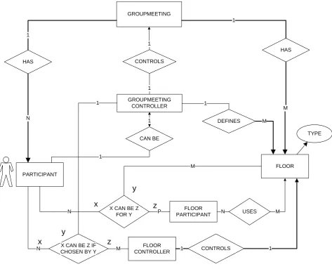
Figure 5 is the final diagram and adds media and media-control to the DTC system. Media and their control are further called floors, as described in Section 3.3.6. Floors are controlled by the teacher. Floors are accessed by both the teacher and the students, according to their rights.
X CONTROLS ACCESS RIGHTS
OFZ TO Y CONTROLS
DTC
USES TO TEACH
USES TO LEARN
TEACHER STUDENT
1
1
1
N
1 N
1
HAS
FLOOR
1
M
ACCESSES
ACCESSES 1
N
M
M M
1
CONTROLS 1
M
TYPE SOURCE
SINK
x
y
z
RIGHTS
Figure 5: Complete diagram.
3.4
Generic desktop teleconference model oriented
HCI-requirements
3.4.1 A generic Desktop Teleconference model
A generic Desktop Teleconference (DT) model, according to the ideas presented in the platinum document [4], models a conference that is hierarchically organised in groupmeetings and floors. Floors were explained in Section 3.3.6 and form a more generic way to use different media like video or audio. Each conference, group and floor has a single controller and a number of participants.
A groupmeeting consists of a number of floors and a number of participants that use/control those floors. One of the participants is the group controller.
All communication is done by using floors. For the handling of requests, a separate mechanism exists.
The above-mentioned ideas will be used to make a generic DTC system. To simplify the design and implementation, there will be only one groupmeeting in this conference. This means that there is no need for the definition and use of conference participants or a conference controller.
3.4.2 Detailed description of the generic desktop teleconference model
The generic DT model consists of one groupmeeting that is controlled by one groupmeeting controller. This groupmeeting has a number of floors and a number of participants that can use or control those floors. These floors are each controlled by a floor controller and have a number of floor participants. Each of those floor participants may, when permitted by the floor controller, access (source and/or sink) that particular floor.
Floor controllers are group participants, assigned to control a floor by the groupmeeting controller.
A floor participant may ask a floor controller permission to access a floor. A floor controller may grant or reject such a request. When a request is granted, a floor participant instantly gains the requested access.
A floor controller can always give or withdraw floor-access rights from floor participants at will.
3.4.3 Description of the scenario, the actors and their roles within a generic Teleconference model
There is only one scenario at this moment for the generic DT model. That is the “simple
Actor Participant
Roles
Groupmeeting controller: A participant who is allowed to manage and release a
groupmeeting. He can create or delete floors and assign floor controllers.
Groupmeeting participant: A participant who has any combination of management and medium access rights.
Floor controller: A participant who controls the access to a floor.
Floor participant: A participant who may have or request access to a floor.
In this scenario, we have one groupmeeting controller and a number of groupmeeting participants.
3.4.4 Detailed lecture scenario for a conference system using a generic desktop Teleconference model
Groupmeeting Controller (GC):
A groupmeeting controller enters a conference and therefore (there is only one) the groupmeeting and identifies it. He can create and delete floors and assign the accompanying floor controllers. He can take part in the groupmeeting. At the end, he will leave the groupmeeting.
Floor Controller (FC):
A floor controller gets floor control rights. He thereafter controls the access rights of the floor participants to the floor and uses that to manage the floor in order for the discussion on his floor to run smoothly. At the end, he will release or lose his floor control rights.
Groupmeeting Participant (GP):
A groupmeeting participant enters a conference and identifies himself. After that, he takes part in the groupmeeting by becoming floor-controller and/or floor participant for a number of floors in order to have access to a number of floors.
He can always leave a groupmeeting.
Floor Participant (FP):
A floor participant joins a floor by asking and getting sink-access for a floor to the floor
controller. He can also ask for source-access for the floor to the floor controller or release access. He can always leave a floor by releasing source- and sink-access for that floor.
A more detailed description can be found in Appendix D.
Because right are important within such a hierarchical model as this generic DT model, these are treated separately.
A Groupmeeting Controller is allowed to:
- Start and end the Groupmeeting
- Add and delete the Groupmeeting Participants to the Groupmeeting
- Add and delete Media to the Groupmeeting
- Assigns Floor Controller to media
A Floor Controller allowed is to:
- Start and end Participant’s access to the Medium
- Grant or reject a Participant’s request for Media Access to the Medium
A groupmeeting participant is allowed to:
- Request to Groupmeeting Controller to become floor-controller
- Leave Groupmeeting
- Leave Conference
A floor participant is allowed to:
- Depending on Medium access rights, read and write from/to this Medium
- Request the Floor Controller for Access Rights to a Medium
- Leave floor
It might be possible for a floor to have no controller at all. In that case, access to that floor might be free for all floor participants, or may be according to fixed rights.
Next, follow some diagrams that explain the relations between the different roles and components of the system in more detail.
3.4.6 Task analyses for a conference system using a generic Teleconference model
The task analysis are mostly derived from the scenarios mentioned above can be found in Appendix D.
The result of the scenario in appendix D is a global description of the cohesion and functionality of all defined roles within a generic DT model. The result of the task analysis in Appendix D is a large set of tasks that can be performed for each role within that given scenario.
3.4.7 Entity-Relationship diagrams
To describe the actors, their roles and their mutual coherence more clearly, not only point wise scenario-definitions and task analysis, but also E-R diagrams will be used.
These E-R diagrams will be presented separately for different aspects of the DTC. A stepwise refinement will be used to introduce details at a later stage. After that, a last diagram, containing an E-R diagram of the complete generic DT model in full detail, will be given.
GROUPMEETING
HAS HAS
1 1
PARTICIPANT USES FLOOR
N M
N M
Figure 6: Simple E-R diagram of a groupmeeting.
Figure 7 adds all controllers with respect to the groupmeeting and floors. A groupmeeting controller controls the whole groupmeeting and therefore may define floors and appoint floor controllers and floor participants. A floor controller may decide the access-rights to his floor for all floor participants.
GROUPMEETING
HAS
HAS 1
1
PARTICIPANT
FLOOR N
M CONTROLS
1
CAN BE GROUPMEETING
CONTROLLER 1
1
1
CONTROLS
N FLOOR 1
CONTROLLER 1 X CAN BE Z IF
CHOSEN BY Y M X CAN BE Z
FOR Y
FLOOR PARTICIPANT P
N
M
x
y
z
USES
N M
TYPE
x y
z
1
DEFINES 1
M
Figure 7: More detailed diagram of a groupmeeting.
A Groupmeeting has participants and floors
Each floor is of a certain type (e.g. audio, video, text)
A participant can be a groupmeeting participant. One participant can be a groupmeeting controller.
The groupmeeting controller controls the groupmeeting.
Several participants can be floor controller for a certain floor or a floor participant for a certain floor.
Figure 8 gives the relation between the groupmeeting, the groupmeeting controller and groupmeeting participants in a separate E-R diagram in more detail.
GROUPMEETING
HAS 1
GROUPMEETING PARTICIPANT
N CONTROLS
1
GROUPMEETING CONTROLLER
1
Figure 8: The relation between group controller and group participant.
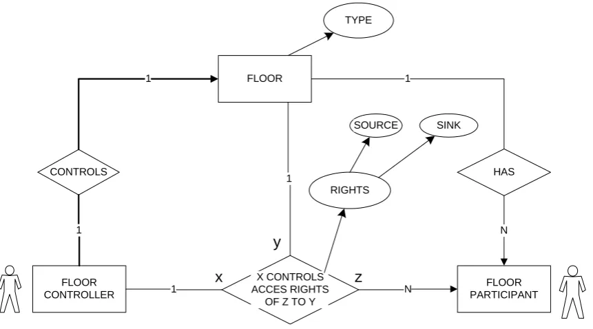
Figure 9 gives the relation of floors, floor controllers and floor participants in a separate E-R diagram in more detail.
FLOOR
CONTROLS
FLOOR CONTROLLER
X CONTROLS ACCES RIGHTS
OF Z TO Y
HAS
FLOOR PARTICIPANT RIGHTS
SOURCE SINK
1
1
1
N
1 N
1
x
y
z
TYPE
Figure 9: The relation between floor controller and floor participant. - A floor has a number of floor participants and a floor controller. - The floor controller controls the floor.
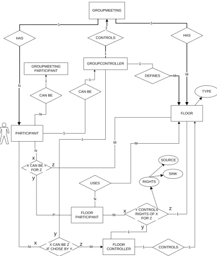
In Figure 10, all former E-R diagrams are combined into one single E-R diagram.
GROUPMEETING
HAS HAS
1 1
PARTICIPANT
FLOOR N
M CONTROLS
1
CAN BE
GROUPCONTROLLER 1
1
1
CONTROLS N IF CHOSE BY YX CAN BE Z M CONTROLLERFLOOR 1 1
FLOOR PARTICIPANT
1 X CAN BE Y
FOR Z N
Y CONTROLS RIGHTS OF X
FOR Z P
M
x
y
z
1
M x
y
z
SOURCE
SINK
RIGHTS
TYPE CAN BE
GROUPMEETING PARTICIPANT
1
N
1
x z
y
DEFINES 1
M
USES
M
N
3.5
The mapping of the DTC system to a system using a generic
desktop teleconference model
In this part, we will map the roles from the generic DT model as defined in Section 3.4 onto the actors from the DTC system as described in Section 3.3. When this mapping is applied to that Generic DT model, it will give us the desired system that has all the functionality of the defined DTC system, but is more generic.
3.5.1 The mapping of the systems
In short, one can summarise the former chapters as follows:
Each participant is an actor with a single role within the DTC system. An actor within the DTC system has an educating role as a student or a teacher.
The actor, a participant, from the generic DT model has one or more roles in that DT model. To those roles belong certain rights.
These two descriptions can be combined into one description:
Each participant is an actor with a single role within the DTC system. An actor within the DTC model has an educating role as a student or a teacher and has one or more roles in the generic DT system. To those roles belong certain rights.
Figure 11 represents this in an E-R diagram.
PARTICIPANT IS
ACTOR HAS EDUCATING
ROLE
CAN BE TEACHER
CAN BE STUDENT
Figure 11: Mapping diagram.
A mapping diagram from the participants in the generic DT model to the actors in the DTC system
GROUPMEETING
Figure 12: All combined
3.5.2 The mapping of the actors and roles
The mapping in Figure 12 is not yet complete. The actual mappings from actors in the Desktop Tele-classroom Conference system to the roles in the generic Desktop Teleconference system must still be determined.
If we look at the teacher/student scenario’s, we must conclude that the teacher has all control over the group and over the media (floors) because he can admit or refuse students from a meeting and he is the only one that who can grant the floor to someone.
The mapping from teacher and student to roles can be summarised as follows:
A teacher is always the group controller. A student is always a group participant.
A teacher is floor controller for all floors present. A student is a floor participant for all floors present.
In Short:
Groupmeeting Controller
Floor Controller Groupmeeting
Participant
Floor Participant
Teacher Yes All floors - -
Student - - Yes All floors
Table 2
4 HCI design for the DTC system
4.1 Introduction
The interaction of the DTC system with its users, (i.e. the whole of functionality between the users and the DTC system) has been defined as a number of tasks that those users, defined by their roles, can perform within the DTC-system (see Chapter 3).
The HCI for the DTC system must provide that interaction with its users by offering a number of functions to perform all those tasks. These tasks, as in Chapter 3 defined, will therefore guide the design of the HCI.
These tasks are dependent on the role that a particular user has. Therefore, also the functionality that the HCI offers can differ for each user, depending on the role that the user has within the system. For instance: a normal student must not be allowed to prevent everybody from speaking.
The actual design is meant for a DTC system, but a number of design-features for a more generic desktop conference system [as described in Chapter 3] are kept in mind because the DTC system can be extended.
4.2 General overview of the functionality of the HCI from the
DTC system
4.2.1 Generic conference system functionality
When we look at the scenarios and task analyses from Chapter 3.4 and Chapter 3.5, a number of generic functions can be distinguished.
• When a user starts or enters the system, he first has to identify himself and the conference he
wish to join. In this procedure, the user not only assigns himself a unique identity that can be used throughout the system. He also defines his initial role and the accompanying initial rights for that session within the DTC system.
• The HCI must provide control functions for each local medium like audio or video. In
addition, it must provide functions to use each floor that has been defined.
• Another general function that the HCI has to offer is disconnection from the groupmeeting
and return to the enter-groupmeeting part.
• When a user has a role as a groupmeeting controller, the HCI has to offer functions to control
the groupmeeting. This means that the HCI has to offer functions to create floors and to assign control of those floors to groupmeeting participants that thus become floor controllers.
• When a user has a role as groupmeeting participant, the HCI has to offer functions to request
• When a user has a role as a floor controller, the HCI has to offer functionality to control the assigned floors. This means that the HCI has to offer functions to enable read and/or write access for one or more of these floors, if requested.
• When a user has a role as floor participant, the HCI has to offer functions to request and
return read and/or write access for one or more floors.
• When a user has a role as a controller (floor or groupmeeting), the HCI has to offer a list of
all participants present, to give the controller a general overview.
The HCI that is being designed here is not meant to be a complete generic conference system, but must at least offer the functions of a DTC system as described in Chapter 0. This means that not all functionality as mentioned above has to be implemented in this cycle.
4.2.2 DTC system functionality
Mapping
The functionality of the HCI for the DTC system is smaller than that of the generic DT model because there are only two actors defined: Teacher and Student.
Still, some provisions must be made to keep the HCI more universal. This has the advantage that the functionality of the DTC is easier to extend during a later design cycle. Therefore, a restricted implementation of a system according to the generic DT model as described in Section 4.2.1 will be designed with a mapping of generic roles to specific DTC-actors.
In a Generic DT model, as described in Section 3.5.2, the teacher has the roles of groupmeeting controller and of floor controller for all floors. A student has the role of groupmeeting participant and of floor participant for all floors. Groupmeeting will be the same as “classroom”.
Restrictions
Since the teacher is both groupmeeting controller and floor controller for all floors, it is not necessary for the HCI to offer functions to assign floor control to groupmeeting participants. The teacher is only concerned with floor control. Therefore, the decision was made to implement group control functions only as a mock-up.
Because each student has to be able to follow a lecture using all available floors, it is not necessary to provide functions to request read access for floors. Instead, sink-, or read access- rights should be given to a student by default for all floors. The decision was therefore made to let all users always have sink-rights.
4.3
The mapping from tasks to functionality
In order to design the functionality of the HCI for the DTC system according to a limited generic DT model, we first have to map each task from the task analyses in appendix D to functions that the HCI has to offer to the user. This mapping is done in appendix E and results in a list of functions that, when implemented, the HCI must offer to the user.
Those tasks and functions are related to roles in a generic DT model. Later, those DT-roles can be mapped onto roles from the DTC system according to the mapping as given in Section 3.5.2.
4.4 The different HCI main-elements of the DTC application
4.4.1 Division into HCI-views
To give the user a better understanding of the functionality of the system and to enable the user to find a desired function more quickly, the HCI will be split up in different parts. These each represent a different logical “block” of functions that have a strong cohesion. These parts are called “HCI-views”. Each of those HCI-views will get a separate, coherent, visual representation within the system because of the coherence of its functionality. A user can, according to the defined relations between those HCI-views, switch between them.
This approach is illustrated within the Platinum documents [4].
4.4.2 The HCI-views
From the former section (4.2), we can derive de following main HCI views.
1. A HCI view for entering a groupmeeting.
2. A HCI view for inspecting the groupmeeting.
3. A HCI view for modifying the groupmeeting.
4. A HCI view for inspecting access to a number of floors
5. A HCI view for modifying access to a number of floors
6. A HCI view for requesting access to a number of floors.
7. A HCI view to control local media.
8. HCI views for adapting and using floors.
Hereby the decision was made to combine the functionality of inspecting, modifying and
requesting. This is done for both groupmeeting and floors. This is the case from the second HCI view up to the sixth HCI view. This is done because, in the generic conference system, a floor controller can also be a floor participant for another floor. This means that, when not combined, there would be two separate HCI-views that provide functions on the same subject (i.e. floor-access or floor-control). This would be confusing for the user and use a larger part of the
This results in the following main HCI views
1. A HCI view for entering the groupmeeting
2. A HCI view for inspecting and modifying the groupmeeting
3. A HCI view for inspecting, modifying and requesting access to a number of floors
4. A HCI view to control local media.
5. HCI views for adapting and using floors.
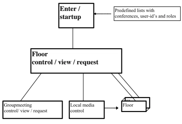
4.4.3 Relation between the HCI views
Floors (use) Enter /
startup
Floor
control / view / request
Groupmeeting control/ view / request
Local media control
Floor
Predefined lists with
conferences, user-id’s and roles
Figure 13: How the main parts of the HCI are bound together.
The user always starts at 1 (enter groupmeeting), where the user, his role and the groupmeeting will be defined.
As central HCI view, the floorcontrol HCI-view is the best choice. This is mainly the case because it gives an overview of the groupmeeting and provides the very basic tools for a DTC system for both the teacher and the student. Such a central view will be presented immediately after the start-up HCI-view. The HCI-view for groupmeeting control is higher from a
hierarchical point of view and therefore seems also a logical choice. However, this will not be used very often, even in complete system according to a generic DT model, because control of floors is not likely to change quickly. In this case, for the DTC system, the second HCI-view will hardly be implemented or used. The HCI for local media control will probably be used often, but is very low from a hierarchical point of view and therefore is not the best choice to use as a central HCI-view.
These other HCI-views deal with groupmeeting control, local media control, and floor-access. Local media control will take care of properties for audio and video and therefore has a direct effect on some floors. The HCI-views for floor-use deal with the actual use of floors, that have media like text-chat or a whiteboard that need their own HCI, or the access-control to media on a per-floor base.
This is all illustrated in Figure 13.
4.5
The fully designed HCI-views within the DTC system
4.5.1 Considerations for all HCI-view descriptions
All demanded functionality as defined by the function as derived from task analyses in Appendix E, will be divided over the different HCI-views.
- Per function, a short description of how the HCI will handle this will be given.
- A number of functions will not be fully designed yet. These are given in a separate section.
A number of very general functions will always be available:
Status field
In order for error messages to appear, a kind of status field with continuous changing messages is necessary. This status field would appear in all larger windows so the user always knows it when problem has arisen.
Quit/hide function
To return to a former level of the HCI or to clean up the desktop, a user must always have the possibility to quit or hide a particular HCI-view.
4.5.2 A HCI view for entering a groupmeeting
This must be one single basic entry-window that acts as a kind of gateway to the rest of the system. The following functions must be offered according to the task analyses in appendix C and D.
Entering a unique personal identification number
This will be done in a normal input field.
Choosing of a groupmeeting
Here, the best solution would be an input field, combined with a pull down list to chose or type the name or number of the desired groupmeeting.
Join conference
user-ID check /college ID/ roles
The user identification number and groupmeeting identification must be entered or chosen and must match each other before a conference can be joined. When a conference is joined, the match of identification number and conference determines the user’s role. When a conference can’t be joined, an error message must appear.
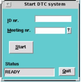
In Figure 14 is the visual appearance given for such an HCI view.
Figure 14 The login HCI-view.
4.5.3 A HCI view for inspecting / modifying / requesting floors
Assuming that all controlled floors are represented in one HCI view, the following functions must be offered according to the task analysis for the different roles.
General presented information
Presentation of all floor participants
This view is presented as a central view from which other views will be called. This means that this HCI-view must have the functionality to call all other HCI-views. This can be done with the help of buttons and menus. It also means that this HCI-view must present the before mentioned general information.
The presentation can be done in a number of ways. The most common ones are a table and a list. Within a table, the requests and rights can be shown or specified for each participant and for each floor separ