University of Windsor University of Windsor
Scholarship at UWindsor
Scholarship at UWindsor
Electronic Theses and Dissertations Theses, Dissertations, and Major Papers
2012
Vehicle lightening with composite materials: Objective
Vehicle lightening with composite materials: Objective
performance comparison of material-systems for structural
performance comparison of material-systems for structural
applications
applications
Davide Scuccimarra
University of Windsor
Follow this and additional works at: https://scholar.uwindsor.ca/etd
Recommended Citation Recommended Citation
Scuccimarra, Davide, "Vehicle lightening with composite materials: Objective performance comparison of material-systems for structural applications" (2012). Electronic Theses and Dissertations. 4839.
https://scholar.uwindsor.ca/etd/4839
This online database contains the full-text of PhD dissertations and Masters’ theses of University of Windsor students from 1954 forward. These documents are made available for personal study and research purposes only, in accordance with the Canadian Copyright Act and the Creative Commons license—CC BY-NC-ND (Attribution, Non-Commercial, No Derivative Works). Under this license, works must always be attributed to the copyright holder (original author), cannot be used for any commercial purposes, and may not be altered. Any other use would require the permission of the copyright holder. Students may inquire about withdrawing their dissertation and/or thesis from this database. For additional inquiries, please contact the repository administrator via email
VEHICLE LIGHTENING WITH COMPOSITE MATERIALS:
OBJECTIVE PERFORMANCE COMPARISON OF
MATERIAL-SYSTEMS FOR STRUCTURAL APPLICATIONS
by
Davide Scuccimarra
A Thesis
Submitted to the Faculty of Graduate Studies
through Mechanical, Automotive, and Materials Engineering in Partial Fulfillment of the Requirements for
the Degree of Master of Applied Science at the
University of Windsor
Windsor, Ontario, Canada
2012
VEHICLE LIGHTENING WITH COMPOSITE MATERIALS:
OBJECTIVE PERFORMANCE COMPARISON OF
MATERIAL-SYSTEMS FOR STRUCTURAL APPLICATIONS
by
Davide Scuccimarra
APPROVED BY:
______________________________________________ Dr. Faouzi Ghrib, External Reader
Department of Mechanical, Automotive & Materials Engineering
______________________________________________ Dr. Peter Frise, Internal Reader
Department of Mechanical, Automotive & Materials Engineering
______________________________________________ Dr. Jennifer Johrendt, Advisor
Department of Mechanical, Automotive & Materials Engineering
__________________ ___________________________ Dr. Vesselin Stoilov, Chair of Defense
Department of Mechanical, Automotive & Materials Engineering
DECLARATION OF ORIGINALITY
I hereby certify that I am the sole author of this thesis and that no part of this thesis has
been published or submitted for publication.
I certify that, to the best of my knowledge, my thesis does not infringe upon anyone’s
copyright nor violate any proprietary rights and that any ideas, techniques, quotations, or
any other material from the work of other people included in my thesis, published or
otherwise, are fully acknowledged in accordance with the standard referencing practices.
Furthermore, to the extent that I have included copyrighted material that surpasses the
bounds of fair dealing within the meaning of the Canada Copyright Act, I certify that I
have obtained a written permission from the copyright owner(s) to include such
material(s) in my thesis and have included copies of such copyright clearances to my
appendix.
I declare that this is a true copy of my thesis, including any final revisions, as approved
by my thesis committee and the Graduate Studies office, and that this thesis has not been
ABSTRACT
In recent years many studies proved that the adoption of polymer composites represents
an effective solution to reduce the weight of vehicles.
In this context, the goal of this study is the design of a rear suspension cradle made of
composite material, with particular attention to aspects such as recyclability and high
volume production of the component.
Starting from the CAD model of the existing aluminum part, a simplified shape that
represented it was designed and FEM analysis was conducted using the software
ABAQUS; materials, geometry and fiber orientation were changed in order to obtain a
composite model with the same performance as the aluminum model but with lower
weight. The performance of the composite and aluminum models were compared.
In addition, a manufacturing process and a method of recycling for the optimal composite
ACKNOWLEDGEMENTS
I wish to express my greatest gratitude for my advisor, Dr. Jennifer Johrendt and my
Chrysler tutors Dr. Saad Abouzahr and Dr. Jian Tao in providing continuous support and
helpful ideas in the course of my research: I could learn in knowledge and method of
research working under their supervision.
I would like to thank my thesis committee members, Dr. Peter Frise and Dr. Faouzi Ghrib
for their valuable comments and recommendations.
Finally, I would to express my gratitude to Jan Stewart and Mike Houston for their
presence and suggestions during the months I spent here in Canada: I really appreciated
TABLE OF CONTENTS
DECLARATION OF ORIGINALITY ... iii
ABSTRACT ... iv
ACKNOWLEDGEMENTS ... vi
LIST OF TABLES ... ix
LIST OF FIGURES ... xi
CHAPTER I. INTRODUCTION 1.1 Overview ...1
1.2 Objective and Outline of the Thesis...6
II. REVIEW OF LITERATURE 2.1 Composite Materials – Overview ...7
2.2 Fiber Materials ...11
2.2.1 Carbon Fibers ...12
2.2.2 Glass Fibers ...16
2.2.3 Aramid Fibers ...18
2.3 Resin Materials ...19
2.3.1 Thermoset Resin ...19
2.3.1.1 Epoxy ...19
2.3.1.2 Polyester ...20
2.3.2 Thermoplastic ...21
2.3.3 B – Stage Epoxy...22
2.4 Processes ...23
2.4.1 Braiding...23
2.4.2 Thermoforming ...25
2.4.3 Compression Molding ...27
2.4.4 Injection Molding...30
2.4.5 RTM (Resin Transfer Molding) ...32
2.4.6 Melding ...35
2.5 Sandwich Structures...36
2.6 Recyclability ...40
2.6.1 Carbon Fiber Recycling Processes...42
2.6.1.2 Fiber Reclamation ...43
2.6.1.3 Pyrolisis...44
2.6.1.4 Oxidation in Fluidized Bed ...44
2.6.2 Chemical Recycling ...44
2.6.3 Composites Re-Manufacturing ...46
2.6.3.1 Injection Molding...46
2.6.3.2 BMC Compression...46
2.6.3.3 Compression Molding ...47
2.6.3.4 Woven rCFRP ...48
2.6.4 Issues of Carbon Fiber Recycling ...49
2.6.5 Applications for rCFRP ...51
2.7 Applications of Composite for Structural Components ...53
III. DESIGN AND METHODOLOGY 3.1 Problem Statement ...62
3.2 Proposed research ...65
3.3 Development of Composite Model ...75
IV. ANALYSIS OF RESULTS 4.1 First Composite Solution ...81
4.2 Second Composite Solution ...83
4.3 Third Composite Solution ...84
4.4 Torsional Stiffness ...96
4.5 Summary of the Results ...103
V. CONCLUSIONS AND RECOMMENDATIONS 5.1 Conclusions ...107
REFERENCES ...112
LIST OF TABLES
2.1Summary analysis of different recycling processes . . . 42
2.2 Mechanical properties of recycled CFs reclaimed through different processes . . . 45
2.3 Mechanical Properties of recycled CFRPs manufactured with different processes 48
2.4 Demonstrators manufactured with recycled CF . . . 50
2.5 Estimated values for the cost of carbon fibers. . . 50
2.6 Potential structural applications for rCFRPs . . . 53
3.1 Stiffness values of the original aluminum component . . . 64
3.2 Stiffness of aluminum model along different directions . . . .74
3.3 Carbon fiber reinforced polymers mechanical properties . . . 76
3.4 Glass fiber reinforced polymer mechanical properties . . . 76
4.1 Stiffness of first composite solution along different directions . . . 82
4.2 Stiffness of the second model along different directions . . . 83
4.3 Stiffness of the third model along different directions . . . 85
4.4 Stiffness values of third composite solution. Fiber orientation -45°/45°symmetric. 86 4.5 Stiffness values of third composite solution. Fiber orientation 0°/90° symmetric . . 87
4.6 Stiffness values of composite model with threshold value of thickness . . . 88
4.7 Stiffness values of glass fiber composite model. Fiber orientation -45°/45°symmetric 4.8 Stiffness values high modulus carbon fiber composite model. Fiber orientation -45°/45°symmetric . . . 96
4.9 Torsional stiffness of aluminum model . . . 98
4.10 Torsional stiffness of composite model with conventional carbon fiber . . . 98
4.11 Torsional stiffness of composite model with glass fiber . . . 99
4.12 Composite model A. Conventional carbon fiber. Fiber orientation -45°/45°. Weight 2.16 kg . . . 103
4.13 Composite model B. Conventional carbon fiber. Fiber orientation -45°/45°. Weight 2.16 kg . . . 103
4.15 Composite model C. Conventional carbon fiber. Fiber orientation -45°/45°. Weight 4.11 kg . . . .104
4.16 Composite model C. Conventional carbon fiber. Fiber orientation 0°/90°. Weight 4.11 kg . . . .104
4.17 Composite model C. Conventional carbon fiber. Fiber orientation -45°/45°. Weight 3.75 kg . . . .105
4.18 Composite model C. Glass fiber. Fiber orientation -45°/45°. Weight 4.11 kg . . . .105 4.19 Composite model C. High modulus carbon fiber. Fiber orientation -45°/45°. Weight 4.11 kg. . . 105
4.20 Torsion: composite model C. Conventional carbon fiber. Fiber orientation -45°/45°. Weight 3.75 kg . . . 106
LIST OF FIGURES
1.1Historical trends of vehicles in the U.S . . . 2
1.2Material composition of future lightweight vehicles . . . . . . 3
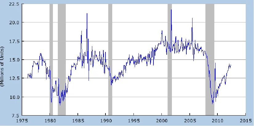
1.3a Annual automotive material processing energy demand under different scenarios . 4 1.3b Number of vehicles sold from 1975 to 2012 . . . 5
1.4Material processing energy demand per vehicle sold . . . .5
2.1 Mechanical properties of fiber, resin and FRP composite . . . 8
2.2 Stress-strain curve for FRP composites . . . 9
2.3 Transfer printing of VACNTs to prepreg . . . 10
2.4 Hybrid interlaminar architecture . . . 11
2.5 Raw materials process . . . 12
2.6 Carbon fiber typical process flow diagram . . . 15
2.7 Properties of carbon fibers (from different precursor materials) and other types of fibers . . . 15
2.8 Scheme of 3D braiding process . . . 24
2.9 Steps of vacuum thermoforming process . . . 26
2.10 Compression molding process . . . 29
2.11 Scheme of injection molding process . . . 30
2.12 Some ranges of the sizes of materials for injection molding process . . . 32
2.13 Resin Transfer Molding Process . . . 34
2.14 Melding procedure . . . 35
2.15 Bending behavior of a sandwich structure . . . 37
2.16 Honeycomb structure with phenolic resin . . . 38
2.17 Chemical structure of Nomex . . . 38
2.18 Sandwich structure with honeycomb . . . 39
2.19 Closed life-cycle of CFRP . . . 41
2.20 Main technologies for CFRP recycling . . . 43
2.21 Mechanical properties of recycled carbon fibers and their virgin precursors . . . 45
2.23 Preliminary composite underbody design . . . 54
2.24 Composite-to-steel weld bond joint . . . 55
2.25 Fabric Mat fed into SMC Compounder . . . 56
2.26 Molded underbody hung from bungee cord for modal testing . . . 58
2.27 Underbody quasi-static ODB subassembly test . . . 59
2.28 Three points bending tests on the corrugated sandwich composite coupon . . . 60
2.29 Experimental load-displacement curves of the corrugated composite sandwich coupon under bending conditions . . . 60
2.30 Stress distribution of composite sandwich coupons . . . 61
3.1 Rear suspension cradle-CAD model . . . 62
3.2 Cradle: attachment points and load points . . . 63
3.3 Simplified model of cradle with aluminum material . . . 66
3.4 Location of constrained points . . . 67
3.5 Location of applied loads- Force acting on Lower Link . . . 67
3.6 Location of applied loads-Force acting on Upper Link . . . 67
3.7 Aluminum model Lower lateral link - Displacements with force applied along x-direction . . . 68
3.8 Aluminum model Lower lateral link - Displacements with force applied along y-direction . . . 68
3.9 Aluminum model Lower lateral link - Displacements with force applied along z-direction . . . 69
3.10 Aluminum model Upper lateral link - Displacements with force applied along x-direction . . . 69
3.11 Aluminum model Upper lateral link - Displacements with force applied along y-direction . . . 70
3.12 Aluminum model Upper lateral link - Displacements with force applied along z-direction . . . 70
3.13 Aluminum model Lower lateral link - Stress distribution with force applied along x-direction . . . 71
3.15 Aluminum model Lower lateral link - Stress distribution with force applied along
z-direction . . . 72
3.16 Aluminum model Upper lateral link - Stress distribution with force applied along x-direction . . . 72
3.17 Aluminum model Upper lateral link - Stress distribution with force applied along y-direction . . . 73
3.18 Aluminum model Upper lateral link - Stress distribution with force applied along z-direction . . . 73
3.19 Definition of composite materials properties with Abaqus software . . . 77
3.20 Definition of sections with Abaqus software . . . 80
4.1 Model of composite solution A . . . 81
4.2 Model of composite solution B . . . 83
4.3 Model of composite solution C . . . 84
4.4 Composite Model C Lower Lateral Link - Displacements with force applied along x-direction . . . 88
4.5 Composite Model C Lower Lateral Link - Displacements with force applied along y-direction . . . 89
4.6 Composite Model C Lower Lateral Link - Displacements with force applied along z-direction . . . 89
4.7 Composite Model C Upper Lateral Link - Displacements with force applied along x-direction . . . 90
4.8 Composite Model C Upper Lateral Link - Displacements with force applied along y-direction . . . 90
4.9 Composite Model C Upper Lateral Link - Displacements with force applied along z-direction . . . 91
4.10 Composite Model C Lower Lateral Link - Stress distribution with force applied along x-direction . . . 91
4.11 Composite Model C Lower Lateral Link - Stress distribution with force applied along y-direction . . . 92
4.13 Composite Model C Upper Lateral Link - Stress distribution with force applied
along x-direction . . . 93
4.14 Composite Model C Upper Lateral Link - Stress distribution with force applied along y-direction . . . 93
4.15 Composite Model C Upper Lateral Link - Stress distribution with force applied along z-direction . . . . 94
4.16 Location of applied loads- Moment acting on Lower Link . . . 97
4.17 Composite Model C Lower Lateral Link - Displacements with moment applied along rx direction . . . 100
4.18 Composite Model C Lower Lateral Link - Displacements with moment applied along ry direction . . . 100
4.19 Composite Model C Lower Lateral Link - Displacements with moment applied along rz direction . . . 101
4.20 Composite Model C Upper Lateral Link - Displacements with moment applied along rx direction . . . 101
4.21 Composite Model C Upper Lateral Link - Displacements with moment applied along ry direction . . . 102
4.22 Composite Model C Upper Lateral Link - Displacements with moment applied along rz direction . . . 102
4.23 Summary of results: Bending stiffness of Lower Lateral Link [N/mm] . . . 108
4.24 Summary of results: Bending stiffness of Upper Lateral Link [N/mm] . . . 109
4.25 Summary of results: Torsional stiffness of Lower Lateral Link [Nmm/rad] . . . 109
CHAPTER I
INTRODUCTION
1.1 Overview
In the recent years the rising trend of oil prices and an increasing awareness of the human
contribution to the environmental pollution and global warming lead to an increased
interest on fuel-efficient solutions for ground transportation. The result of this new
approach has been a thorough search for light weighting options, which consist of the
transition to alternative and more fuel-efficient powertrains and activities aimed at
reducing vehicle weight [1].
In this context, the adoption of polymer composites represents an effective solution to
reduce the weight of vehicles: large vehicle users, such as trailer truck operators, have
already tested the benefit of the adoption of such technology for light weighting and their
use will increase in this market share.
However, the need for weight reduction was less severe in relatively lighter weight
passenger cars in the past and as consequence the introduction and anticipated growth of
polymer composites in this market share will be slow.
But the tendency is to size reduction of vehicles and it will bring to a shift of sales away
Figure 1: Historical trends of vehicles in the U.S. [2]
For this reason, in recent years automakers’ automobile designs have started to
incorporate composite solutions in mid-priced automobiles where formerly composites
were justified only in very high-end cars, as market drivers such as crashworthiness take
precedence over weight savings.
It has been proved through vehicle simulations that fuel consumption is reduced by 0.4
l/100km for cars, and 0.5 l/100 km for light trucks for every 100 kg of weight reduction.
In other words, for every 10 % weight reduction, fuel economy increases by 6 % for cars
Figure 2: Material composition of 2016 lightweight vehicles [2].
In Figure 2 it is shown how the overall weight of cars will reduce in 2016. According to
this prediction, the curb weight of an average new vehicle in 2016 weighs -480 kg than
today (i.e. 28% less) [2]. It is possible to notice which materials will increase their
percentage in the vehicle, in particular composites, aluminum and high-strength steel will
have a steep increase in future years.
The adoption of new kinds of material will also affect the automotive material production
energy demand: it is defined as the amount of energy required to produce/process
Figure 3a: Annual automotive material processing energy demand under different
scenarios [2]
Looking at the trend for future years depicted in Figure 3a, the demand levels off, despite
increasing sales, as the effect of accounted efficiency improvements take place. The drop
in the energy demand verified around 2009 is due to the decrease in the number of sold
vehicles in the same period (Figure 3b). Shaded areas correspond to peaks or drops of
sold vehicles.
The production energy demands for four different scenarios are observed to be similar.
Obviously, if no improvements are adopted the energy demand will be higher similarly
with the adoption of more advanced power trains that weigh more and require more
Figure 3b: Number of vehicles sold from 1975 to 2012 [Source: ALTSALES-US
Department of Commerce]
Figure 3a shows that pursuing a lightweight strategy implies a lower production impact,
despite greater use of more energy-intensive aluminum. A further improvement to this
result can be obtained by the adoption of alternative lightweight materials pathways, such
as composite materials.
In the future, the decline in material processing energy demand can be explained by
efficiency improvements in materials processing, and due to the 15 % average new
vehicle weight reduction depicted in the scenario. The relative magnitude of these two
effects is shown on the same figure (Figure 4) by considering their effects separately.
This reveals that the material processing improvements are responsible for most of the
decline in the production impact.
1.2 Objective and Outline of the Thesis
The goal of the present research is the design of a rear suspension cradle made of
composite material, with particular attention to aspects such as recyclability and high
volume production of the component.
Starting from the production part mounted on the 2011 Dodge Dart 2.0 WGE Tigershark,
a new model will be designed in order to study the feasibility of the conversion of the
component from aluminum to composite material, obtaining the same or higher
mechanical performance of the existing part but with lower weight.
The first step of this work will be the choice of the material and process more suitable to
have a recyclable component for high volume production.
Then, depending on the previous choice, the design phase will be conducted: starting
from the CAD model of the existing part, a simplified shape will be designed that
reproduces it and FEM analysis will be conducted using the software ABAQUS, applying
the same load conditions of the original case. A comparison between solutions with
aluminum and composite material will be done, highlighting the results of the composite
solution with respect to the metal one.
As explained before, the goals of the work will be a composite component that has a
comparable mechanical performance as the aluminum solution, but with a lower weight.
Once the best solution in terms of design and material has been selected, a suitable
manufacturing process for the component will be chosen, without providing specific
information regarding the times and cost necessary for the production.
A method to recycle the component will be proposed according to the available
CHAPTER II
REVIEW OF LITERATURE
2.1 Composite Materials – Overview
Fiber reinforced polymer composites (FRP) are being widely used for structural
applications where high mechanical properties together with low weight are required, and
they constitute a valid alternative in comparison with metal materials.
The key point of composite materials is that they optimize the performance of
conventional materials, in terms of mechanical behavior and lightness. This benefit is
obtained through the combination of more than one material; for example, a matrix
material with certain properties can be combined with a fiber that has different properties
and the result is a material that highlights the best characteristics of both. Generally, a
composite material is composed of at least two components or phases which are
combined in different proportions and shapes.
Fiber reinforced polymer materials (FRP) are made of a continuous polymeric phase, the
matrix, which assures a certain shape to the component and especially transmits the load
uniformly to the reinforcement phase, the fiber, which has to absorb the amount of
mechanical solicitations. Fibers can be of several types and shape, but the most common
are glass fiber (GRP) or carbon fibers (CRP).
Due to the presence of a continuous (matrix) and a discontinuous (fiber) phase, composite
materials have anisotropic characteristics in terms of elastic properties and mechanical
resistance. The anisotropic grade depends on the orientation of the fibers inside the
matrix: in particular it is higher for those composites which have a parallel disposition of
the fibers, while it is lower if they are disposed with varying or random orientations.
The simplest type of fiber-matrix system is the ply, which is a layer of composite material
where all the fibers are parallel and they define the longitudinal direction of the same ply.
According to the previous definition, the mechanical response of the single ply will differ
depending on the direction of the load, parallel or orthogonal to it, and on the number of
plies adopted.
In Figure 5 it is shown how the presence of the fiber in the polymer matrix leads to a
material with improved mechanical properties (especially tensile strength) when
compared to a material made of only the polymeric matrix.
Figure 5: Mechanical properties of fiber, resin and FRP composite [13]
In order to exploit the mechanical properties of the fiber and improve both the resistance
and the stiffness of the composite structure, it is fundamental to realize a good bonding
along the surface of the interface between matrix and fiber. The external load is applied
to the matrix but it is transmitted to the fiber through the shear friction along the surface
mentioned previously (especially for those fibers that are not extended for all the length
of the matrix).
The critical length for the fiber is defined as that beyond which the axial load is
considered constant (this critical length is function of the type of the fiber, the interface
Regarding the mechanical properties of the FRP, it is possible to indicate two critical
points for the mechanical behavior of such materials. As it can be seen in Figure 6, there
is a maximum load beyond which the structure completely collapses. In this situation
both the fiber and the matrix fail [13].
Nevertheless, before this point a laminate can reach a stress condition that leads to the
formation of micro cracks in the matrix, which are detrimental for the mechanical
properties of the composite material. For this reason, it is fundamental to ensure that a
structure that has plies which do not exceed this point in presence of regular loads. The
maximum stress that a laminate can withstand before the occurrence of micro-cracking
depends on the adhesive properties of the resin.
Figure 6: Stress-strain curve for FRP composites [13]
The fatigue behavior of FRP composites is influenced by the hardness of the resin, its
resistance to micro-cracking and the grade of adhesion between matrix and fibers.
The bonding property of the system matrix-fiber is determined by the nature of the resin
and can be improved through surface treatments of the fibers, namely applying a proper
agent on the surface of the fibers.
Another way to improve the adhesion between matrix and fibers has been exploited in
in dispersing CNT in polymers at high weight fractions while achieving uniform and
strong interactions with the polymer matrix. Moreover, studies of hybrid composites
using unoriented CNTs dispersed in polymers reported only negligible mechanical
property improvements at low CNT loadings.
The solution for these problems consisted of aligning the CNTs and organizing them with
long-range order, realizing mechanical improvements [14].
One method to establishing such order is by spinning ropes of discontinuous CNT as a
new type of advanced carbon fiber. Another solution is to modify existing advanced
composite systems to create hybrids; dispersion and alignment challenges for
nano-composites are even more pronounced when the CNT is processed into matrix with a
high volume fraction (approximately 60%) of advanced fibers.
Since the interface between plies in advanced composites is more accessible from the
processing aspect than the laminate interior, several studies have realized marginal to
nano-modified interfacial properties using carbon nano-fibers (CNF) and CNT at
laminate interfaces [14].
One approach could be to integrate aligned CNT with existing carbon fiber prepreg
materials and processing.
This is accomplished by growing a vertically-aligned CNT (VACNT) forest at high temperature, and then ‘transfer-printing’ the CNT to prepreg at room temperature, taking
advantage of the tack of the prepreg to separate the CNT from the growth substrate.
The process used to transplant the VACNT to a prepreg is shown in Figure 7A. The
prepreg is attached to a cylinder that is rolled and pressure is applied across the substrate
containing the CNT forest to transfer the CNT to the prepreg: the transfer rate, pressure,
and geometry are set until full transplantation of the CNT forest is achieved.
Figure 8 shows how the VACNTs are placed between composite plies and how they
contribute to bridge the cracks.
Figure 8: Hybrid interlaminar architecture: (A) VACNTs placed in between two plies and
(B) effect of VACNTs bridging the crack between two plies [14]
Further developments of CNT will lead to a great interest fabricating shorter aligned
CNT forests to reduce the interlayer thickness and thereby focus on bridging.
2.2 Fiber Materials
In Figure 9 the raw materials pipeline is depicted: starting from raw fibers and resins,
they are manufactured and several types of composite products can be achieved,
depending on the specific application. Focusing the attention on the fiber manufacturing
section of the pipeline of Figure 9, in the production of composite materials many
different types of fiber can be used; the most common are carbon fibers, glass or aramid
Figure 9: Raw materials process [18]
2.2.1 Carbon Fibers
The interest in carbon fibers for structural materials was initiated in the late 1950s when
first experiments were conducted to carbonize synthesized rayon in textile form to
produce carbon fibers for high temperature applications.
One of the first distinctions to be made for this kind of fibers is the difference between
Carbon and graphite fibers are both based on graphene (hexagonal) layer networks
present in carbon: the material is defined as graphite if the graphene layers stack with
three dimensional orders. Usually for graphite fibers extended time and temperature
processing are required to form this three dimensional order, and this aspect makes these
fibers more expensive. Nevertheless, disorder frequently occurs in the layers because the
bonding property between planes is weak, so only the two dimensional ordering within
the layers is present: this kind of material is defined as carbon. There are several other
conditions which contribute to differentiate carbon from graphite fibers, and even
graphite fibers retain some disorder in their structure, while some differences are implied
[18].
In order to produce carbon fibers three different precursor materials are commonly used:
rayon, polyacrylonitrile (PAN), and isotropic and liquid crystalline pitches. Among the
previous materials, PAN is the most common: carbon fibers are made mainly from its
carbonization [18]. The fiber graphite with basal planes tends to align along the fiber axis
and this forms an internal structure that is similar to an onion skin, while pitch fibers may
have a different internal structure, reminding to sheaves or spokes.
This kind of materials present high levels of anisotropy due to their morphology and this
leads to a great variability in the moduli range: they vary from 200 to 750 GPa along the
direction parallel to the fiber long axis, while they are lower in the normal direction of the
fiber axis, around 20 GPa. To make a comparison, a single crystal of graphite is about
1060 and 3 GPa, for the directions parallel and normal to the axis of the fiber, but these
properties are not attainable in fiber form and these values are lower after the processing
[18]. Nevertheless, ultra high modulus fibers can be prepared from liquid-crystalline
mesophase pitch; they give higher moduli because the precursor material has a higher
degree of orientation and this translates through to the final carbonized fiber generating
larger and more oriented graphite crystallites [18].
As a consequence of previous considerations, carbon fiber properties are dependent on the fiber microstructure, which is deeply affected by the process which is adopted; in this
way, such that properties of fibers can be highly different even if their precursor materials
are the same but a different process has been used to their production. In this context,
fiber, taking into account the application of the fiber and the costs involved in their
production.
For example, carbon fibers from PAN have a lower cost respect to the other precursors,
which makes them more competitive in the market maintaining a good compromise
between cost and quality of the fiber [18].
In the following it will be described the manufacturing process for carbon fiber for the
PAN variant, which is one of the most common and, as told before, most cost effective.
The manufacture of PAN based carbon fiber can be divided into the white fiber and
black fiber stages: they are generally described in the following [18].
The production of PAN precursor, or white fiber, is considered a technology in
itself due to its complexity; for this stage conventional fiber processes are performed:
polymerization, spinning, drawing, and washing, even if additional drawing steps may be
added in the process. It is important to notice that the characteristics of the white fiber
deeply influence the processing and results for the black fiber processing, so it is
fundamental to achieve a good quality of the same.
The black fiber process consists of several steps: oxidation (or thermosetting), pyrolysis
(or carbonizing), surface treatment, and sizing. In the oxidation process the PAN fiber is
converted to a thermoset from a thermoplastic. For this oxidation process the fiber
diameter is limited by waste gas diffusion. In the pyrolysis process, which is performed
under an inert atmosphere, most of the non-carbon material is expelled, forming ribbons
of carbon aligned with the fiber axis [18].
In the surface treatment step the fiber may be etched in either gas or liquid phase to
improve the wet ability for the resin and enhance the formation of a strong bond; this can
be realized through oxidizing agents such as chlorine, bromine, nitric acid or chlorates.
Some additional improvement may also be realized through removal of surface flaws.
The carbon fibers are often treated with solution of unmodified epoxy resin and/or other
products as a size. The sizing prevents fiber abrasion, improves handling, and can provide an epoxy matrix compatible surface. From the experience in this field, it has been proved
that PAN precursor can provide higher strength carbon fibers, while pitch can provide
higher moduli. In Figure 10 white fiber and black fiber processes are schematized.
fibers tend to be less expensive but have lower performance. In Figure 11 this
characteristic of Rayon based fibers can be noticed; in addition, differences between pitch
and PAN fibers are evident in terms of tensile modulus, tensile strength and cost. In the
past pitch fiber composites have been prepared with elastic moduli superior even to steel
and electrical conductivity higher than copper conductor even if the shear strengths and
impact resistance are degraded. The yield for PAN is approximately 50%, but for pitch
can reach 90%.
Figure 10: Carbon fiber typical process flow diagram [18]
Figure 11: Properties of carbon fibers (from different precursor materials) and other
2.2.2 Glass Fibers
Glass fiber are characterized by an elevated strength (at least double if compared with the
best steel), good stiffness (similar to aluminum), low cost, low thermal and electrical
conductivity, high maximum temperature of operation (between 500 and 1000 °C).
There are principally two different kinds of glass fiber for the manufacture of composite
materials:
E: it is the most utilized and economic type of glass fiber. It is composed of silica
(50 %), alumina (15 %) and calcium and boron oxides; it has low electric
conductivity and originally it was employed in the electric sector;
S: it is essentially constituted of silica (65%), alumina (25 %) and magnesia
(10%) and it is characterized by a high strength.
Then there are several other types of glass fibers that are utilized for special and
dedicated purposes.
For many years glass composites have had a distinct strength to weight advantage.
Although the rapid evolution of carbon and aramid fibers has gained advantages, glass
composite products have still prevailed in certain applications.
In particular, the advantages related to glass fibers are a low cost per weight or volume,
chemical or galvanic corrosion resistance, good electrical properties, and the possibility
to realize many product forms. While the typical disadvantages of these fibers compared
to carbon ones are the coefficient of thermal expansion and modulus properties, while
respect to aramid fibers the glass ones have worse tensile properties but better behavior
under compression , higher shear properties and moisture pick-up [19].
Typical commercial applications for glass products are filtration devices, thermal and electrical insulation, pressure and fluid vessels, and structural products for automotive
and recreation vehicles. Many uses are applicable to military and aerospace products as
well. As told before, with this wide range of applications it can be seen how glass fiber
structural applications can be considered limitless to fabricate (choosing the proper
process for the particular application) [18]. Compared to other fibers, they have some
limitations linked to their low thermal and electrical conductivity and different melting
temperatures when compared to carbon fibers.
Regarding the manufacture methods for their production, glass fibers are mostly
produced from raw products with additives that are mixed and are premelted into
marbles. This form presents a raw product form for automated feeding to the individual
melt furnaces, diminishing the time of the process. Another method is to feed, via
hoppers, dried raw products directly to batch cans.
Independently from the raw form, the material is fed into furnaces to become molten at
approximately 1500°C. The molten mass flows into plates which contain many bushings
with small orifices from which the individual filaments are drawn. The diameter of the
filaments is controlled by the viscosity of the glass melt and the rate of extrusion. Cooling
or solidification occurs rapidly as the glass leaves the bushings in filament form under
ambient conditions and it is realized through water spray and/or application of the
binders. The individual untwisted filaments are gathered and then high speed wound on
tubes or "cakes". Sometimes finishes are applied after the strands are wound on the tubes
then dried. In order to produce rovings, the strands are then creeled, unwound and
gathered again to form ends or multiple untwisted strands. This process of gathering
or combining is again repeated to form rovings of desired yields (yards per pound).If they
have to be used for weaving of fabrics and braiding, the strands are twisted to form yarns.
Single yarns are composed of single strands twisted by it. Two strand constructions are
two strands twisted to produce a single yarn, while plied yarns are made from twisting
two or more yarns together. Twisting and plying is often referred to as "throwing".
During this process of continuous filament one of the most important variables is the
repeated tensioning required during the numerous product forms fabrication. For this
purpose, tensioning devices are used, such as: disc-type or "whirls", gate-type, tension bars or staple bars, and compensating rolls in the delivery from the creels. Humidity is
another controlled variable in the twisting, plying, and braiding, warping, slashing,
gulling and weaving areas. The common value of the relative humidity is of 60 to 70
must be monitored, especially for devices such as: guide eyes, spacer bars, rollers and
such are subject to wear and must be maintained. These contact devices are manufactured
from materials including: stainless steel, chromium plating, and ceramics [18].
2.2.3 Aramid Fibers
Aramid fibers have a great interest for applications in composite materials due to the
following factors: low density (the density of aramid is 1.44 g/cm3, about 40% lower than glass and about 20% lower than commonly used carbon), high tensile strength, high
tensile stiffness, low compressive properties (nonlinear), and exceptional toughness
characteristics. Moreover, aramid fibers do not melt and they decompose at about 500°C.
The tensile strength of yarn can be varied from 3.4 - 4.1 GPa (in twisting direction) by choosing different types of aramids. The nominal coefficient of thermal expansion is
-5x10⁻⁶ m/m/C° in the axial direction. Since aramid fibers are aromatic polyamide polymers, they have high thermal stability and dielectric and chemical properties, in
addition to excellent ballistic performance and general damage tolerance derived from
fiber toughness. Moreover, composite systems reinforced with aramid have excellent
vibration-damping characteristics and they resist shattering upon impact. Temperature of
use in composite form with polymer matrix ranges from -36 - 200°C. At 60% fiber
volume fraction, composites of epoxy reinforced with aramid fibers have nominal tensile
strength at room temperature of 1.4 GPa and nominal tensile modulus of 76 GPa.
These composites are ductile under compression and flexure and, as a consequence, their
ultimate strength is lower than glass or carbon composites under compression and
flexure. Composite systems, reinforced with aramid, are resistant to fatigue and stress
rupture: under tension/tension fatigue, unidirectional specimens survive 3,000,000 cycles
at 50% of their ultimate stress [18]. Recently, thermoplastic resin composites reinforced
with aramid have been developed and they have exhibited equivalent mechanical
properties compared to similar thermoset systems. In addition, thermoplastic systems
provide potential advantages in economical processing, bonding, and repair. These are
stiffness is less important. Kevlar™49 is predominantly used in reinforced plastics - both
in thermoplastic and thermoset resin systems. It is also used in soft composites like core
of fiber optic cable and mechanical rubber good systems.
Typical applications of aramid fibers are to brake, clutch, and gasket due to their stability
and frictional properties at high temperatures; low coefficient of thermal expansion is
being used in printed wiring boards and exceptional wear resistance is being engineered
into injection-molded thermoplastic industrial parts. Melt-impregnated thermoplastic
composites, reinforced with aramids, offer unique processing advantages -e.g., in-situ
consolidation of filament-wound parts: these can be used for manufacturing thick parts
where processing is otherwise very difficult.
Aramid fiber is relatively flexible and tough. Thus it can be combined with resins and
processed into composites by most of the methods established for glass [18].
2.3 Resin Materials
Resin is a generic term used to designate the polymer, polymer precursor material, and/or
mixture with various additives or chemically reactive components. The resin, its chemical
composition and physical properties, deeply affect the processing, fabrication and
ultimate properties of composite materials. Some variations in the composition, physical
state, or morphology of a resin and the presence of impurities or contaminants in the
same resin may affect handle ability and process ability, lamina/laminate properties, and
composite material performance and long-term durability [18].
Resin for composite material can be divided in two types: thermoset or thermoplastic. In
the following these two types of matrixes are described.
2.3.1 Thermoset Resin
2.3.1.1 Epoxy
The term epoxy is a general description of a family of polymers which are based on
molecules that contain epoxide groups. An epoxide group is an oxirane structure, a
three-member ring with one oxygen and two carbon atoms. Epoxies are thermosetting resins
with amines, acids, amides, alcohols, phenols, acid anhydrides, or mercaptans. The
polymers are available in a variety of viscosities from liquid to solid.
Epoxies are used widely in resins for prepregs and structural adhesives. The advantages
of epoxies are high strength and modulus, low levels of volatiles, excellent adhesion, low
shrinkage, good chemical resistance, and ease of processing. Their major disadvantages
are brittleness and the reduction of properties in the presence of moisture. The
processing or curing of epoxies is slower than polyester resins.
The cost of the resin is also higher than the polyesters. Processing techniques include
autoclave molding, filament winding, press molding, vacuum bag molding, resin transfer
molding, and pultrusion. Curing temperatures vary from room temperature to
approximately 180°C. The most common cure temperatures range between 120° and
180°C. The use temperatures of the cured structure will also vary with the cure
temperature, while higher temperature cures generally yield greater temperature
resistance. Cure pressures are generally considered as low pressure molding from vacuum
to approximately 700 kPa [18].
2.3.1.2 Polyester
The term thermosetting polyester resin is a general term used for orthophthalic polyester
resin or isophthalic polyester resin. Polyester resins are relatively inexpensive respect to
epoxy ones and fast processing resins used generally for low-cost applications. In
combination with certain fillers, they can exhibit resistance to breakdown under electrical
arc and tracking conditions. Isophthalic polyester resins exhibit higher thermal stability,
dimensional stability, and creep resistance respect to orthophthalic ones. In general, for a
fiber-reinforced resin system, the advantage of polyester is its low cost and its ability to
be processed quickly [18].
Fiber-reinforced polyesters can be processed by many methods. Common processing
methods include matched metal molding, wet lay-up, press (vacuum bag) molding,
2.3.2 Thermoplastic
The majority of thermoplastic polymers are composed of a random molecular
orientation and are named amorphous. Amorphous thermoplastics are available in several
physical forms, including films, filaments, and powders. Combined with reinforcing
fibers, they are also available in injection molding compounds, compressive moldable
random sheets, unidirectional tapes and woven prepregs. With this kind of resins the
fibers used are primarily carbon, aramid, and glass.
The use of amorphous thermoplastics as matrix materials for continuous fiber reinforced
composites is a recent development: in particular, the properties of these resins have led
to their consideration for primary and secondary aircraft structures, including interior
components, flooring, fairings, wing skins, and fuselage sections.
The specific advantages of amorphous thermoplastics depend upon the polymer.
Typically, the resins are noted for their processing ease and speed, high temperature
capability, good mechanical properties, excellent toughness and impact strength, and
chemical stability. The stability results in unlimited shelf life, eliminating the cold storage
requirements of thermoset prepregs. Several amorphous thermoplastics also have good
electrical properties, low flammability and smoke emission, long term thermal stability,
and hydrolytic stability.
The primary advantages of amorphous thermoplastics in continuous fiber reinforced
composites are potential low cost process at high production rates, high temperature
capability, and good mechanical properties before and after impact, and chemical
stability. High temperature capability and retention of mechanical properties after impact
have made amorphous thermoplastics attractive to the aerospace and automotive industry.
A service temperature of 350°F and toughness two to three times that of conventional
thermoset polymers is typical. The most significant advantage of thermoplastics is the
speed of processing, resulting in lower costs: typically, cycle times in production are less
than for thermosets since no chemical reaction occurs during the forming process.
The costs of amorphous thermoplastics prepreg used for advanced composites are higher
processing advantages discussed above. The ability to re-process the material results in
reduced scrap rates, translating into additional cost savings. For example, the same sheet
laminate can be thermoformed several times until the desired configuration is achieved,
and in addition certain forms can be recycled.
2.3.3 B – Stage Epoxy
Composites using epoxy resins can be formed and reformed whenever they are heated
above their glass transition temperature (Tg). The reform ability decreases as the degree
of conversion nears the ultimate for that particular epoxy polymer. An epoxy
reinforcement in the B-staged condition can be treated as a thermoplastic material and can be melted and thermoformed.
The degree of cure can be increased in steps or progressions without significant
detrimental effect to the mechanical properties of the composite material. Tailored blanks
can be CNC cut, laminated, rapidly formed and B/staged. These formed and B/staged
blanks can then be fed into the progression molding operation.
There is a point in the epoxy degree of conversion when the cooled lamination is
dimensionally stable enough to withstand unsupported post-cure. This post-molding heat
treatment will yield maximum degree of conversion for each specific epoxy.
Epoxy resins arrive at a prepregger in normally a solid form, typically powdered,
granular or in large chunks; these are then typically dissolved in a solvent (normally
acetone), then mixed with catalysts and the fiber reinforcement is dipped into baths,
excess resin is squeezed off and then the solvent is evaporated away in heating towers or
tunnel ovens. These tunnel ovens drive the state of cure of the epoxy further, but not to
completion. This process is called B-staging the epoxy material [22].
Another method used to mix the solid epoxy resins is by heating and melting them in
reactors or mix vessels effectively reducing the viscosity to a point where the other key
ingredients can be compounded into the mixture. At this stage in the cross-linkage
process the epoxy resin is technically still a thermoplastic and it can be melted, although
into paper or can be directly applied to the reinforcement at this time. When cooled the
resin hardens and returns to the original semi-solid form. The sticky or tacky
characteristics can be controlled by the amount of time at temperature and directly
correlates to the degree of conversion of cure. [23] [25]
However, in the previous description the gradual increase in viscosity of the polymer as
the molecular weight increases during the cure process is not considered and the process
results more complicated and difficult to realize. B-staged epoxy prepregs are normally
characterized by aerospace composites manufacturers by their degree of resin flow,
stickiness, drape, formability or sag. Some manufacturers utilize press molding grades of
epoxy prepreg.
Some applications of B-stage epoxy are: the Gatling Gun Ammo Handling Helix, where a
FG/epoxy prepreg disk has been manufactured through compression molding, and the
Lite-Flex Springs, which are in use on over 15 million vehicles, including GM, Ford,
Range Rover, Chrysler, Iveco, Navistar and others. Especially for the second application,
the fact that this supplier has been able to compression mold very high volumes of thick
walled composite springs is proof that the epoxy chemistry can be utilized for an ever
greater percentage of a typical vehicle or truck chassis [24].
2.4 Processes
2.4.1 Braiding
The braiding process fabricates a preform or final shape at the same time that it generates
the woven form. This product form is a unique fiber reinforcement which can use
preimpregnated yarn as well as dry fibers. The main advantage of the braiding process is
its ability to realize odd shapes and maintain fiber continuity while developing high
damage tolerance compared to unidirectional and laminated products [18]. This particular
characteristic is useful to realize square, oval, and more in general shapes with constant
cross-section. The three dimensional form of braiding has evolved in last years and it is
planes [18].
A demonstration of its versatility is the open-wheel race car body which was fabricated
by braiding.
In the application of biaxial and triaxial braiding, a mandrel is usually used to form the
braid. The mandrel also acts as the mold for the final product. The braiding machine
controls the rate of feed of the mandrel and the rotational speed of the carriers. The
combination of these parameters and the size of the mandrel control the braid angle. The
braid angle, along with the effective yarn, tape, or tow width (width of the specific size
yarn, tape, or tow on the mandrel as placed by the braiding process), ultimately controls
the coverage of the braid on the surface of the fabricated form. As the braid angle
increases, the maximum size of the mandrel which can be covered with a specific
yarn, tape, or tow size decreases. For complicated forms, expendable mandrels may be
used. These include mandrels made from low melting temperature metal alloys and
water-dissolvable casting materials, and collapsible mandrels [18].
Figure 12: Scheme of 3D braiding process [26]
In three-dimensional (3D) braiding process schematized in Figure 12, the weaving
process itself is used to control the shape of the fabricated product. The typical 3D
braiding process involves a bed of cops, or weaving loops, which are moved in a
systematic manner. This systematic movement creates an interwoven product in the x-y
also intertwined. The resulting product is essentially self-supporting because it
interweaves in three directions. For precision exterior dimension, matched metal molds
can be used during the resin matrix curing process. The following are the general steps
involved in the braiding process [18]:
1. Decide the feed speed, cop speed, and weave pattern (for 3D braiding).
2. Run the braiding machine until the product is finished.
3. If prepreg material is not being used, use an appropriate resin impregnation process
(RTM, wet resin impregnation, and so on).
4. Cure according to the appropriate process determined by the impregnation method
(autoclave cure, vacuum bag, RTM, and so on).
5. Remove the part from the mold or mandrel.
2.4.2 Thermoforming
The thermoforming process, as applied to thermoplastic composite materials, is generally
divided into two categories: melt-phase forming (MPF) and solid phase forming (SPF).
Thermoforming exploits the rapid processing characteristics of thermoplastics. The
composite thermoforming process can be divided into four basic steps: firstly, the
material is heated to its processing temperature external to the forming tool (through
radiant heat). Then the oven-heated material is rapidly and accurately transferred to the
forming tool and is pressure-formed with matched die set tooling into desired shape.
Finally, the formed laminate is cooled and its shape is set by sinking the heat into the
tooling [18].
The melt-phase forming is performed at the melting point of the thermoplastic matrix and
requires sufficient pressure and vacuum application during the forming process in order
to provide complete consolidation. In Figure 13 the steps of vacuum thermoforming are
depicted: the plastic sheet is previously heated and then formed with application of
vacuum.
produced presents sharp contour changes that require some level of resin flow.
SPF is generally performed at temperatures between the onset of crystallization and
below the peak melting point. This temperature range provides sufficient formability
while the material remains in a solid form. SPF allows forming of preconsolidated sheet
to be performed without a consolidation phase, but it is limited to part geometries
exhibiting gentle curvatures [18].
The processing time for thermoforming is governed by the rates at which heat can be
added to the material and then removed. This is primarily a function of the material
thermal properties, material thickness, forming temperature, and tooling temperature.
The pressures required to shape the material are dependent on various factors including
part geometry, material thickness, and formability.
Figure 13: Steps of vacuum thermoforming process [27]
The general deformability behavior of thermoplastics also depends on the strain-rate used
during forming and the thermal history of the thermoplastic matrix. The forming process
Mechanical properties;
Dimensional tolerances;
Fiber orientation/alignment;
Residual stress;
Uniformity of the fiber to resin ratio;
Degree of crystallinity;
Glass transition temperature.
The forming process has a significant effect on the quality of the finished part, so high
quality parts with predictable engineering properties require that a well-controlled
thermoforming process developed for specific applications [18].
2.4.3 Compression Molding
Compression molding is a process in which the molding material is generally preheated
and then is placed in an open and heated mold cavity. A plug member applied on the top
closes the mold and exerts a pressure that forces the material into contact with all mold
areas, while heat and pressure are maintained to cure the molding material [28]. In the
Figure 14 the process is schematized.
The materials employed with this process are mostly thermosetting resins in a partially
cured stage, either in the form of granules, putty-like masses, or preforms [28].
Compression molding is a process suitable for composite materials with
high-strength fiberglass reinforcements that require high-volume productions; advanced
composite thermoplastics can also be compression molded with unidirectional tapes,
woven fabrics, randomly oriented fiber mat or chopped strand.
In addition to the advantages listed before, it is one of the lowest cost molding methods
compared with other methods such as transfer molding and injection molding; it wastes
relatively little material, representing an advantage when working with expensive
compounds. However, the drawback of compression molding stands in producing parts
with poor consistency and it is difficult to control flashing with this process, and it is not
Fewer knit lines are produced and a smaller amount of fiber-length degradation is
noticeable when compared to injection molding. Compression-molding is also suitable
for ultra-large basic shape production in sizes that overcome the capacity of extrusion
techniques. Materials that are typically manufactured through compression molding are:
polyester fiberglass resin systems (SMC/BMC), Torlon, Vespel, PPS, and many grades
of PEEK [29].
At the first stages of its application, compression molding was developed to manufacture
composite parts for metal replacement applications, especially to make larger flat or
moderately curved parts. Nowadays, this method of molding is greatly used in
manufacturing automotive parts such as hoods, fenders, scoops, spoilers, as well as
smaller more intricate parts.
The material to be molded is positioned in the mold cavity and the heated platens are
closed by a hydraulic ram. Bulk molding compound (BMC) or sheet molding compound
(SMC) are conformed to the mold form by the applied pressure and heated until the
curing reaction occurs. SMC feed material is cut to conform to the surface area of the
mold; then the mold is then cooled and the part removed [28].
SMC is both a process and reinforced composite material. This is manufactured by
dispersing long strands (greater than 1 inch) of chopped glass fibers (usually, but also
carbon fiber can be used) on a bath of polyester resin. The longer glass fibers in SMC
result in better strength properties than standard bulk molding compound (BMC)
products.
Compared to similar methods, SMC benefits from a very high volume production ability,
excellent part reproducibility, it is cost effective as low labor requirements per production
level is very good and industry scrap is reduced substantially. Weight reduction is also
advantageous, because there are lower dimensional requirements and the ability to
consolidate many parts into one.
Bulk molding compound (BMC) or bulk molding composite is a ready to mold, fiber reinforced thermoset polyester material primarily used in injection molding
and compression molding. The material is provided in bulk or logs. BMC is
manufactured by mixing strands (greater than 1 inch) of chopped glass fibers in a mixer
standard thermoplastic products. Typical applications include demanding electrical
applications, corrosion resistant needs, appliance, automotive, and transit [28].
Figure 14: Compression molding process [30]
The material that has to be processed can be loaded into the mold in the form of sheet or
pellets; then the charge material is heated above its melting point, formed and cooled.
The more evenly the feed material is distributed over the mold surface, the less flow
orientation occurs during the compression stage [29].
Some most critical aspects that must be considered for the development of the
compression molding process are the following ones:
Determining the proper amount of material.
Determining the minimum amount of energy required to heat the material.
Determining the minimum time required to heat the material.
Determining the appropriate heating technique.
Predicting the required force, to ensure that shot attains the proper shape.
Designing the mold for rapid cooling after the material has been compressed into the
2.4.4 Injection Molding
Injection molding is a manufacturing process for both thermoplastic and thermosetting
materials. In this process, material is fed into a heated barrel, mixed, and forced into a
mold cavity where it cools and hardens until it assumes the shape of the cavity [28].
Figure 15: Scheme of injection molding process [31]
A scheme of the injection molding process is depicted in Figure 15.
With this process many polymers (resins) may be used, including all thermoplastics,
some thermosets, and some elastomers; as a matter of fact, in 1995 there were
approximately 18,000 different materials available for injection molding and that number
was increasing at an average rate of 750 per year [28].
The available materials for the process are chosen depending on the required mechanical
characteristics for the final product, but when the material has to be chosen the different
molding parameters must be taken into account. In fact, even if they have good
![Figure 6: Stress-strain curve for FRP composites [13]](https://thumb-us.123doks.com/thumbv2/123dok_us/1438552.1176241/24.612.214.409.303.484/figure-stress-strain-curve-frp-composites.webp)
![Figure 9: Raw materials process [18]](https://thumb-us.123doks.com/thumbv2/123dok_us/1438552.1176241/27.612.150.468.109.485/figure-raw-materials-process.webp)
![Figure 13: Steps of vacuum thermoforming process [27]](https://thumb-us.123doks.com/thumbv2/123dok_us/1438552.1176241/41.612.149.495.319.613/figure-steps-vacuum-thermoforming-process.webp)
![Figure 23: Closed life-cycle of CFRP [38]](https://thumb-us.123doks.com/thumbv2/123dok_us/1438552.1176241/56.612.184.448.410.636/figure-closed-life-cycle-of-cfrp.webp)
![Table 1: Summary analysis of different recycling processes [38]](https://thumb-us.123doks.com/thumbv2/123dok_us/1438552.1176241/57.612.112.563.252.521/table-summary-analysis-different-recycling-processes.webp)
![Figure 27: Preliminary composite underbody design [63]](https://thumb-us.123doks.com/thumbv2/123dok_us/1438552.1176241/69.612.117.536.279.500/figure-preliminary-composite-underbody-design.webp)
![Figure 29: Fabric Mat fed into SMC Compounder [63]](https://thumb-us.123doks.com/thumbv2/123dok_us/1438552.1176241/71.612.132.509.362.648/figure-fabric-mat-fed-smc-compounder.webp)
![Figure 30: Molded underbody hung from bungee cord for modal testing [63]](https://thumb-us.123doks.com/thumbv2/123dok_us/1438552.1176241/73.612.116.542.157.373/figure-molded-underbody-hung-bungee-cord-modal-testing.webp)
