University of Windsor University of Windsor
Scholarship at UWindsor
Scholarship at UWindsor
Electronic Theses and Dissertations Theses, Dissertations, and Major Papers
1-1-1964
A digital controller strategy for optimization and adaptation of
A digital controller strategy for optimization and adaptation of
control systems representable in the phase plane.
control systems representable in the phase plane.
Robert J. Rayzak
University of Windsor
Follow this and additional works at: https://scholar.uwindsor.ca/etd
Recommended Citation Recommended Citation
Rayzak, Robert J., "A digital controller strategy for optimization and adaptation of control systems representable in the phase plane." (1964). Electronic Theses and Dissertations. 6365.
https://scholar.uwindsor.ca/etd/6365
A DIGITAL CONTROLLER STRATEGY
FOR OPTIMIZATION AND ADAPTATION
OF CONTROL SYSTEMS
REPRESENTABLE IN THE PHASE PLANE
BY
ROBERT J. RAYZAK
A Thesis
Submitted to the Faculty of Graduate Studies Through the
Department of Electrical Engineering In Partial Fulfillment
of the Requirements for the Degree of
Master of Applied Science at
University of Windsor
Windsor, Ontario
UMI Number: EC52546
INFORMATION TO USERS
The quality of this reproduction is dependent upon the quality of the copy submitted. Broken or indistinct print, colored or poor quality illustrations and photographs, print bleed-through, substandard margins, and improper alignment can adversely affect reproduction.
In the unlikely event that the author did not send a complete manuscript and there are missing pages, these will be noted. Also, if unauthorized copyright material had to be removed, a note will indicate the deletion.
UMI
UMI Microform EC52546
Copyright 2008 by ProQuest LLC.
All rights reserved. This microform edition is protected against unauthorized copying under Title 17, United States Code.
ProQuest LLC 789 E. Eisenhower Parkway
lu*
APPROVED BY:
I V t
ABSTRACT
This thesis proposes a novel digital method for optimization
and adaptation of control systems representable In the phase plane.
By continually generating Its own optimum trajectories the
digital controller has sufficient Intelligence to discern optimum
switching points and system parameter changes.
The optimum trajectory Is stored in memory as error addressed
to memory position by a pseudo error rate, which is determined by a
difference of error over a constant sampling period. Thus, no direct
measure or calculation of error rate Is necessary.
Simulation studies by digital computer show that this method
Is a worthwhile consideration In the field of optimum adaptive controls,
and awaits the completion of a digital controller being constructed
to Implement and further study the system.
ACKNOWLEDGEMENTS
To Dr. P. A. V. Thomas, who supervised this work and gave
much helpful advice In Its course, must go the author's appreciation.
Acknowledgement is also due the National Research Council
for financial assistance provided for this project.
TABLE OF CONTENTS
ABSTRACT 111
ACKNOWLEDGEMENTS iv
TABLE OF CONTENTS v
I. INTRODUCTION
1. Definitions of Optimization and Adaptation 1 2. Some Previous Workers' Attempts at System
Optimization and Adaptation 2
3. The Author's Preliminary Investigations 3
II. DEVELOPMENT OF DIGITAL COMPUTER CONTROLLER LOGIC ?
III. DIGITAL COMPUTER CONTROLLER REQUIREMENTS
1. Logic Plow Diagram 17
2. Consideration of Computer Speed 19
3. Numbers and Coding In the Digital Computer
Controller 20
IV. SYSTEM SIMULATION
1. The Equations of Error Response 21
2. Theoretical Error Responses 22
(a) Application of Various Step Error Changes (b) Optimum Switching to Ramp Functions
(c) Similar Initial Step Applications, Reduction of System Inertia
(d) Responses for Initial Negative Step Error Changes, Same Inertia Change as In (c)
V. SOME PRACTICAL CONSIDERATIONS
1. Relay Characteristics 29
2. Sampling Time 30
VI. CONCLUSIONS 32
REFERENCES 33
I. INTRODUCTION
In the general field of control system theory, optimization
of error responses plays an important role and a method for system
optimization covering a wide set of disturbances is a most valuable
consideration. Moreover, if the system can in some way detect its own
parameter changes and Is in this sense adaptive, it will perform
optimally under a wider set of conditions and augment the value of the
technique.
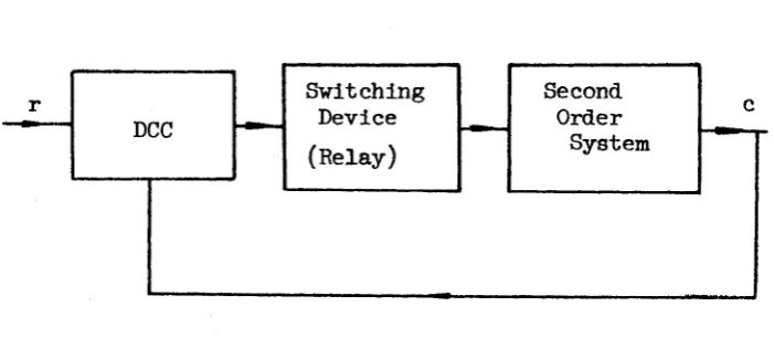
This study proposes a digital computer controller (DCC) method
of c^timization and adaptation of systems representable in the phase
plane. Such a system is shown in Fig. I-l.
DCC
Switching Device
(Relay)
Second Order
System
FIG. I-l SYSTEM CONSIDERED FOR ADAPTIVE OPTIMIZATION
1. Definitions of Optimization and Adaptation.
Whereas systems may be defined to be optimum and adaptive
according to many criteria, this thesis considers the terms in the
following senses.
2
Optimization is taken to mean the reduction of error and
all its derivatives to zero in the fastest possible time. That is,
for a system representable in the phase plane, the system must switch
once at a point corresponding to the intersection of the initial
system trajectory with the optimum zero-trajectory.
Since the term "adaptation" has been given several connota
tions over the past years it is necessary to define adaptation in the
sense used in this thesis. A system which performs to some given
standard (optimally in this study) under one set of system parameters
whose change would normally cause the system to deviate from this
standard and which perfôrms tô the same standard after a change of the
parameters is considered adaptive.
2. Some Previous Workers’ Attempts at System Optimization and Adaptation,
1 2
Other workers in the field * have proposed means of optimiza
tion and adaptation. Brown’s system will be discussed here since the
author of this thesis attempted it initially with the aim of employing
it in more complex systems (i.e., systems which are not pure-inertial).
In Brown's paper a pure inertial system is described where a
linear switching function may adapt itself to the nature of the input
and to slow variations of control system characteristics. However,
Brown’s method has some objectionable features. First, for best results,
the system takes several runs before its response is optimized. In a
practical system whose disturbances and characteristics (parameters)
might be continually changing, optimum response might never be achieved.
Second, the control method requires direct utilization of error rate in
its calculations. Digital implementation of error rate must be achieved
3
considerable time and increased DCC complexity in terms of registers
and the latter are not readily available.
However, other methods of achieving the goals may be readily
proposed subject to considerations of practicality and generality.
The author has investigated several of his own initial proposals and a
few of these will be briefly discussed.
3. The Author's Preliminary Investigations.
For a pure inertia system, it can be readily s h o w n t h a t
optimum performance will occur if the system is switched at a point
where the present error Cg equals one-half the initial error on the
error axis intersection, Gq. Moreover, this criterion is independent
of the system inertia and as such the response will be optimum for any
value of inertia if switched where
6g = E0/2 ( I - 1 )
It was felt that perhaps such a criterion could be developed,
at least empirically, for systems with the general differential equa
tion
a^e + a^ê + a^e = sgn F(e,e) ( I - 2 )
where "sgn" means "the sign of".
Solution of the optimum switching line with the response
curves of a second order damped system in the second and fourth
quadrants of the phase plane readily show such a simple criterion is
not analytically possible.
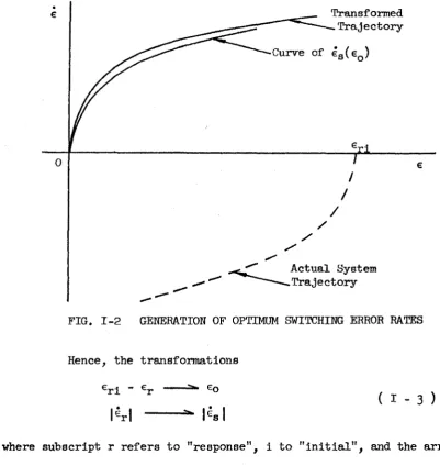
However, if a curve of error rate at switching time, is
plotted against initial error, e^, on the error axis, it is found this
curve approximates an actual positive torque response curve in the
Transformed -Trajectory
Curve of Egfe^)
Actual System •Trajectory
FIG. 1-2 GENERATION OF OPTIMUM SWITCHING ERROR RATES
Hence, the transformations
^ri ^r Go
l^rl ---- ^ l^sl
( I - 3 )
where subscript r refers to "response", 1 to "Initial", and the arrow
indicates "replaces" may be used to generate a curve of optimum
switching points, êg (g q)*
Digital computer simulation of such a control strategy
proved that the errors in switching were too large and response was
sub-optimum. H o w e v e r , the t e c h n i q u e of g e n e r a t i n g a c t u a l s y s t e m
trajectories to use in a control strategy showed promise since adapta
tion would be natural. That is, if the system trajectory changes, the
control strategy will change accordingly.
the phase plane as In Fig, 1-3» The subscript, o, refers to "optimum".
■02
Comparison Level
PIG. 1-3 COMPARISON OF ERROR IN THE PHASE PLANE
Note that time along either trajectory is equal between the
same comparison levels. That is,
( 1 - 4 )
.^on - 1
de
€
^rh - 1 ' ' ^on
L ^ - l ^
Hence, if a memory in the DCC is filled in with values of error on Cg
at successive sampling intervals, T = t^ " ^n - 1^ and compared with
values of error on for successive sampling instants, the point will
occur where e ^ = e^^ and an optimum switch can be commanded by
the DCC. Again, if Cg is continually filled into the DCC memory, the
system will have sufficient intelligence to note a change in its
6
However, for a system with inertia plus viscous damping,
and Cg are not similar and equation (l-4) does not hold. Still, if
instead of addressing the memory for successive sampling times, the DCC
memory is addressed in terms of error difference for successive sampling
times, in effect the DCC memory stores error in terms of error rate.
Hence a complete curve of e(l) is stored in memory for conçmlson against
an actual trajectory.
This concept forms the basis for the major portion of this
thesis which will now deal with logic implementation and simulation of
the above strategy to a second order positioning servo. It is to be
noted however, that the method is in general applicable to any phase
II. DEVELOPMENT OF DIGITAL COMPUTER CONTROLLER LOGIC
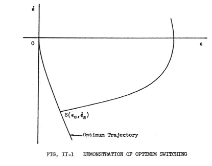
Basically, a system represented In the phase plane will
yield optimum performance when It detects Its own trajectory response
intersecting with the optimum trajectory and switches at this point.
Referring to Fig. II-l It can be seen that the system will
switch at point S(6g,êg) when the errors and error rates of the
response trajectory and the optimum trajectory correspond. This proce
dure may be achieved In the following manner.
Optimum Trajectory
FIG. II-l DEMONSTRATION OF OPTIMUM SWITCHING
If the optimum curve Is stored In memory for comparison
between an arbitrary response and itself then optimum switching will
occur at an intersection. However, it is not convenient to compute or
8
measure error rate directly by digital means. As has been demonstrated
in section I of this thesis error may be compared at constant level
changes in error rates up to the switching point. This concept leads
to the primary decision strategy in the DCC,
It is known that error rate may be approximated by the rela
tion,
e(t) « ^ ( II - 1 )
where cg is the present error considered and is the previous error
considered. The time difference, At, is the time between these two
values.
Now if the DCC samples error every T seconds then
£p “ £■]
e : ( II - 2 )
However, it was noted that if the DCC samples error at a
constant T then only a difference in error will define the error rate.
That is,
AE = Gg - è ( II - 3 )
The DCC will have a memory eind in lieu of storing error and
error rate for comparison, error alone may be stored in a memory at
the address Ae. In an actual DCC to be built e and hence a e will be
integral values. Thus, the upper bound of memory locations will be
the highest integral error rate expected.
If a response error presented for comparison is denoted as
Gr(AEr) and an error stored in memory as e^(Ae^) then the decision
process for optimum switching is
IS e^(AE^) ^ ? ( II - If )
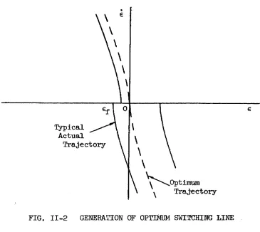
The problem now arises as to how to obtain the memory curve.
Fig. II-2 shows that an optimum switching curve is the negative torque
response shifted along the e-axis- The various negative torque
trajectory portions shown indicate that an optimum curve is given by
Copt. = - 6f ( II - 5 )
where is the curve offset from origin an*i ^act the actual response
error.
Typical Actual
Trajectory
.Optimum Trajectory
FIG. II-2 GENERATION OF OPTIMUM SWITCHING LINE
Hence an optimum response curve may be stored in memory by
storing the negative torque portion of the response as e^(A%) « Com
parison in Fig. II-l is made according to equation (II-4) if
- Cf -- ^ ( II - 6 )
However, comparison may be effected in the second quadrant
10
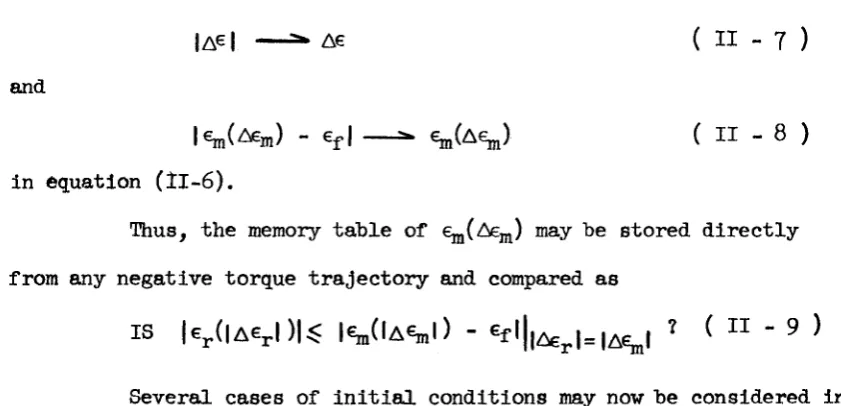
I AG I A€ ( II - 7 )
and
|€jn(A£j„) - €f.| --- ( II - 8 )
In equation (ÎI-6 ).
Thus, the memory table of €g,(AE^) may be stored directly
from any negative torque trajectory and compared as
IS |€^(|AGj.| )|^ |Cm(lA%l) - ? ( II - 9 )
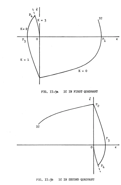
Several cases of Initial conditions may now be considered in
order to develop more fully the controller for table fill-in and
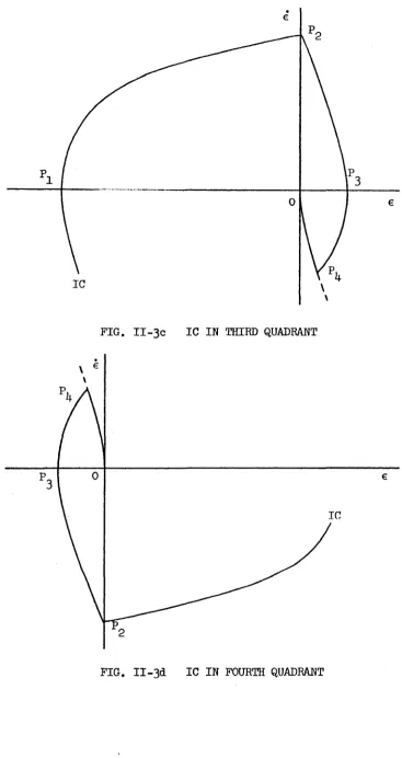
comparison. Figs. Il-ga-d show four general initial conditions (IC)
and resulting responses assuming no table in memory is initially avail
able for comparison. The points (l=l,2,3,4) shown on the figures
have the following meanings.
Pi, start to compare actual response with blank table.
Pg, start to fill in table after switching on sgn (e).
P-, stop filling in table and start to compare table with acutual , response. Store
P|^, switch optimally.
Some general conclusions may be made from consideration of
these figures. First, comparison of an actual response with the
optimum switching line is made only if
iGgI < Icql ( II - 10 )
that is, starting on the e-axis.
Second, the table is placed in memory only when there is a
switch on a change of sgn (e). It will be seen later to avoid undesir
able responses the table should be filled only after the first switch
11
IC
K = 2
FIG. II-3a IC IN FIRST QUADRANT
IC
12
IC
FIG. II-3c IC IN THIRD QUADRANT
IC
13
implemented by setting an index, K, on switching and not filling in the
table if K > 1, The index K is increased by unity after each switching
and is varied throughout the controller execution as will be described.
The table fill-in process will be halted for Ae^. = 0 and at
this time K + 1 — K will take account of this fact.
It is to be noted, however, that switching should occur (at
Pj^) after index K > 1 at the compare command after switching on sgn (e)
for em initially unfilled table in memory. In fact, K = 3 here. In
order to not compare again, the condition K = 3 l8 set to override the
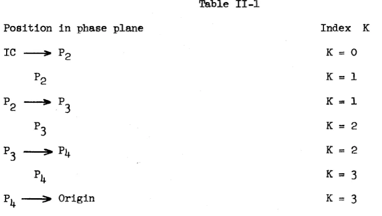
compare command. The various values of K corresponding to the on
Fig. II-3a are given in Table II-l.
Table II-l
Position in phase plane Index K
IC --- > Pg K = 0
Pg
K
=
1
Pg P3 K = 1
P3 K = 2
P > Pi^ K = 2
P
4
K = 3
> Origin K = 3
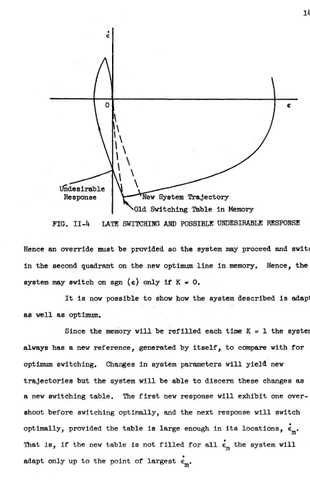
It has been noted that switching on sgn (g) is undesirable f o r K > O. This may he explained by reference to Fig. II-4.
Here the system has switched late on a previous table after
some change in system parameters. The negative torque trajectory
follows the new parameter response. If switching on sgn (e) were now
14
Undesirable
Response " ^ e w System Trajectory
Old Switching Table In Memory
FIG. II-4 LATE SWITCHING AND POSSIBLE UNDESIRABLE RESPONSE
Hence an override must be provided so the system may proceed and switch
In the second quadrant on the new optimum line In memory. Hence, the
system may switch on sgn (e) only If K = 0,
It Is now possible to show how the system described Is adaptive
as well as optimum.
Since the memory will be refilled each time K = 1 the system
always has a new reference, generated by Itself, to compare with for
optimum switching. Changes In system parameters will yield new
trajectories but the system will be able to discern these changes as
a new switching table. The first new response will exhibit one over
shoot before switching optimally, and the next response will switch
optimally, provided the table is large enough in its locations,
That is, if the new table is not filled for all the system will
15
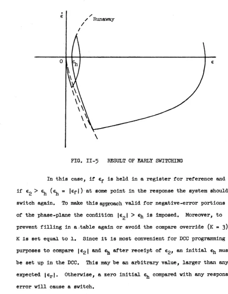
Another possible response on a change of system parameters
Is to switch early. This phenomenon in depicted in Fig. 11-^, with
the accompanying remedy.
/ Runaway
FIG. II-5 RESULT OF EARLY SWITCHING
In this case, if is held in a register for reference and
if Eg > (e^ = |€f|) at some point in the response the system should
switch again. To make this approach valid for negative-error portions
of the phase-plane the condition |eg| > is imposed. Moreover, to
prevent filling in a.table again or avoid the compare override (K = 3)
K Is set equal to 1, Since it is most convenient for DCC programming
purposes to compare leg,] and after receipt of e g , an Initial must
be set up in the DCC. This may be an arbitrary value, larger than any
expected |€j.|. Otherwise, a zero initial compared with any response
16
It is possible that there will be no value of corres
ponding to €j.(Gj,), that is, this memory location will be empty. On a
compare command the system will respond as if the table were blank
and not switch optimally. Hence, some means must be provided to
present a value of for comparison. Since the table is filled
in decreasing values of and the next location |6i„-ll be
filled with also. If the position is filled on the next
sample period then the old |%_i| will be replaced by a fresh correct
value. In the event there is no new value filled in the table, the
system will at worst switch early at this position. Perhaps more than
one location might have to be filled in this manner. It is easiest
to discover the table gaps by system simulation as in section IV,
where it was found for this particular system and sampling time only
one memory location at most was skipped.
A final consideration for logic design in the DCC is the
initial switching of the relay. This is readily accomplished by
checking the sign of the initial error and giving the appropriate
switching signal.
The complete DCC logic has been described. The next section
will consider DCC requirements to implement the logic described in
III. DIGITAL COMPUTER CONTROLLER REQUIREMENTS
The overall system controller operation is given ty the block
diagram of Fig. III-l. The DCC samples error every T seconds, operates
Relay Signals Digital
Computer Logic
To
Relay
FIG. III-l OVERALL DIAGRAM OF DCC
ôn this error, and signals the relay device to switch at the appropriate
place in the phase plane.
1. Logic Flow Diagram.
A logic flow diagram is now considered to implement the
control strategy developed in section II. A complete flow diagram is
given in Fig. Ill-2.
Several "IS" comparison blocks are shown. For the comparisons
of the form
18
V/
M
«
OJ O
CQ
Q
S
CVI
:
19
IS (A - B) ^ 0 ?
It is possible to write
IS (B - A) ^ 0 ?
This is an alternate procedure and may be used in a DCC where
0 is treated as a positive number.
Equation (lI-9) may also be modified slightly for computer
utilization if desired. Since
- ^ ( 0)
the choice exists as to whether this value should be taken from memory
or a register. For memories with slow access time it will be best to
to place this value in a register. However, the flow diagram indicates
Sf as %(0).
2. Consideration of Computer Speed.
The sample time, T, may now be taken into account. Since
the present sampled error, Sg, is given by a digital encoder, it is
desirable to have a new error sampled only after the computer has gone
through its longest logic sequence. "Longest" refers to real time,
and hence the actual minimum sample time T is the longest logic
sequence time in the computer, Tg. Hence, most accurate results occur
if
T = Tg «
The type of memory and its access time is quite important
in obtaining minimum Tg. A delay line memory will take at most one
cycle time to reach a particular position in memory, A much improved
memory would be one with Immediate access.
A special purpose DCC is being built by R. Shiner to implement
20
cycle time of 5 msec. The simulation in section IV has assumed a
sampling time of 1 msec, to achieve most accurate results so as not to
otscure the merits of the method. When Tg for the particular computer
has heen calculated the simulated sampling time should he adjusted
accordingly.
The simulation also indicates the accuracy of the final
values of (g, g) and will help place a tolerance in the computer logic
to open the relay.
The number of hold registers necessary in the computer are
also indicated by the logic. It is seen that K, and 3 must be
registered for use in the course of the programme. Ultimately a
register for eg and other values in the system might be required
depending on the implementation.
3. Numbers and Coding in the Digital Computer Controller.
The actual DCC being built will use integer numbers only.
Hence, the memory is addressed as integral values. The present computer
has
60
locations so the absolute error rate limit is (O,6o).
Errorrate is measured as ASj, from a digital encoder whose range is (O, 1023)*
It is left to determine the actual addressing of Ae in memory as a
location using such a code. This may be done using this code in the
simultation. For example, if Sg = 1010 and e^ = 9^0, then a s = 30«
This is not necessarily e = 30 and memory location 30 should not be
IV. SYSTEM SIMULATION
The System described in this thesis has been simulated on a
digital computer to obtain an indication of expected responses and to
provide a simple means for further studies without using the actual
system. Fig. IV-1 gives a block diagram of the overall system being
DCC Relay
Device
Motor
G(s)
Digitizer
FIG. IV-1 SYSTEM UNDER SIMULATION
Simulated.
In the simulation the relay was assumed to be an ideal device
with states (l,-l). Some discussion on non-ideal relays and dual-mode
servo operation is given in section V.
1. The Equations of Error Response,
The actual transfer function of the motor under consideration
is of the form
G(s) = ---^ ---- ( IV - 1 )
Js + Ds
where K* is the system gain constant, J Is the system moment of inertia,
22
+K' •
r + / ^ 1 c
L
-K' e s^(Ts + 1)FIG. IV-2 SECOND ORDER SYSTEM YIELDING ERROR RESPONSE OF EQUATION IV-2
and D is the viscous damping of the system. No units are assigned to
these parameters for convenience. For some particular system, units may
be assigned to obtain responses to compare with actual responses.
1|. For a relay system of the form in Pig. IV-2 Hopkin and Wang
give an error response of the following form (T is the system time
constant):
e(t) = e(0) + r(o)t + r ( 0 ) ^ + K 7 t - T[+k'
+ ; ( 0) - 1(0)1 (1 -
( IV - 2 )
Moreover, the system will be limited to step and ramp changes
of error eind it is assumed the reference is unchanged. Hence, r(0) =
r(o) = r(0) = 0, and equation (lV-2) can be written in terms of the
transfer function of equation (iV-l) as
e(t) = e(o) + gt - g[+g - e(0)](l - e j ) ( I V - 3 )
which is the response o p t i m i z e d here.
2. Theoretical Error Responses.
Responses of the following four types were obtained with the
various initial conditions imposed to check for optimization and
23
(a) Application of Various Step Error Changes
Step error initial conditions were applied to the system in
the following sequence;
6
(
0) =
3-
0,
2-
7,
1-
4,
2-
3,
3'
2,
3"
2,
1-
0.
Time responses in the sequence of applied initial errors are given in
Fig IV-3. The system parameters were not changed.
The responses indicate that the system is optimized for
initial errors ^ a previous initial error (assuming no parameter change).
Moreover, the system optimizes after the first application of this type
of error. If a new initial error is larger than a previous initial
error imposed, the system response will first be sub-optimal (e.g.
response (l) ) and exhibit one overshoot, then optimal for errors ^
this initial error (e.g. responses (s), (3 ), and (4) ). This phenomenon
is due to the fact that the switching table was not filled in to
accomodate large 6j.(êj.) and was empty to this response.
(b) Optimum Switching to Ramp Functions
Two similar ramp error changes, l(o) = 40, e(o) = 0, were
applied to the system for two consecutive responses. No parameter
changes were allowed. These responses are given in Fig. IV-4.
From equation (IV-3) it may be seen that the phase plane
trajectories will be distorted as well as shifted along the e-axis for
ramp error disturbances. Hence, unless the next application of ramp
error were similar to the previous one, the process depicted in Fig.
IV-4 would be repeated. This deficiency can be overcome at the expense
of increased DCC memory by a three-dimensional table of ejjj(A%, e(o)).
2k
(0
/// ///
///
lA
VO
CO
o
o
o
o
CO
V
9) ra
E4
1
m I
25
•H
■p
CO
m m
26
In this response test, the system inertia was changed after
the first response is allowed to settle and two additional similar
initial errors were applied. Here, the new system inertia will cause
an early switch and a tendency toward system runaway. The system
responses are given in Fig. IV-5 for the following initial conditions
and parameters.
e(0) e(0) K* J D
Run 1 3.2 0.0 10.0 0.01 0.20
Run 2 3.2 0.0 10.0 0.006 0.20
Run 3 3.2 0.0 10.0 0.006 0.20
In Fig. IV-6 a phase plane representation of response (2) is
given to show the effect of switching after a change of inertia
( * ^ n e w ^ ^ o l d )•
In Fig. IV-6 the system switches at on the old optimum
trajectory which is an early switch for the new system. At Pg the fact
of an early switch has been recognized and another switch takes place.
However, the new system trajectory has been filled in memory starting
at P^, and at P^ the system will optimally switch. If no new para
meter change is effected, the system will switch optimally on the next
application of an initial error e such that e <
(d) Responses for Initial Negative Step Error Changes, Same Inertia
Change as in (c)
This final test is given to demonstrate response to negative
initial conditions. The results were mirror images of those in Fig.
IV-5 and are not given here.
In all the responses, a-d, it was noted that the maximum
27
•H
en
ro
3 ^HOHaa imsxs
tf\
ü (Ü 03
S
I
m
o
I
§
I
I
w
§
g
IPv
I
28
\01d OptlmuBi Switching Line in Memory
PIG. IV-6 PHASE PLANE REPRESENTATION OF FIG. IV-5
be said the responses are optimum within 5 % . These errors are due
to digital measurements which takes only a finite sampling of the
responses. For smaller sampling times, responses would be recognized
more accurately.
There are several possible initial conditions other than
those shown in a-d that might be imposed on the system. However, the
responses can be predicted from the above responses as the DCC programme
V. SOME PRACTICAL CONSIDERATIONS
For the system simulated herein an ideal switching device
(relay) with states (l,-l) has been assumed. Also, the relay was
assumed to switch instantaneously on a control signal.
The simulated DCC acted fast enough to perform all its
required logic between small sampling times but had no knowledge of
response between sampling times.
1. Relay Characteristics.
In the actual system to be constructed relay characteristics
will play an important role. Most relays will have the characteristic
shown in Fig. V-1. The deadband, D, present represents a small eimount
of signal that must be overcome before the relay acts (pull-in or drop
out signal). Hence the control signal must be at least > D/2 to ensure
proper relay switching.
Relay State
D
I
—
Control S i g n a l
30
It must also be decided what hounds must he placed on the
origin error so that it is effectively zero, requiring an open relay.
In digital computation techniques exact zero values are impractical
for consideration. As the relay is under complete control of the DCC
some tolerance must he built into its appropriate computation stage to
open the relay. To prevent opening the relay and leaving the system
at a finite point (e, e) in the trajectory the system could be operated
as a "dual mode" system. In this scheme, the system is operated in a
linear manner for some selected small error.
Also, compensation for the time required for relay switching
must he made. If the relay takes T seconds to switch over on receiving
a control signal then the relay must he switched
T
seconds earlierthan its calculated point. This prediction is impossible to make in
time so a compromise must be made on a wide range of phase plane
responses. In Fig. V-2 an optimum trajectory is shown with the effect
of switching late due to relay lag timeT. Ideally the relay is
commanded to switch on However, due to relay lag time the system
switches at Cg,IT seconds later. It is known however that
■I?
and hence A6 = may be calculated. The system should then be
switched if the error is within of the o p t i m u m curve.
2. Sampling Time.
As mentioned previously, sampling time is determined by the
computation speed of the DCC. Hence, systems which may be optimized by
31
FIG. V-2 ILLUSTRATION OF RELAY-LAG RESPONSE
many sampling periods between a total response.
Since the DCC is sampling error between finite times, T,
no recognition of inter-sampling time error is made. It will be
assumed that the error exhibits no radical responses between sampling
VI. CONCLUSIONS
The method of optimization and adaptation of a phase plane
representable control system by means of comparing actual error
trajectories with a self-stored optimum switching line in a DCC has
been demonstrated to be a useful contribution to control system
development. The method is direct, requires no elaborate calculations,
and does not require an actual measure of error rate. Moreover, the
method has been shown by simulation to be easily implemented on a
control computer for actual use.
The technique of self-storing of optimum system trajectories
by addressing memory with error difference for both optimization and
adaptation purposes is believed to be novel in the field.
In the future it is hoped that further studies will be
performed on an actual system to provide further evaluation of the
method’s usefulness and functioning for disturbances of the type
considered here and for random disturbances.
33
REFERENCES
1. Coales, J. F., and Noton, A. R. M. ; An On-Off Servo Mecheinlsm with Predicted Changeover, Proceedings I.E.E., Vol. IO3, Page k k 9 , August 1955»
2. Brown, R. F.; A Calculation of Switching Functions as a Means of Minimizing terror in an On-Off Control System, Proceedings Ï.É.ÿ., Vol. lt>7. Page 249, April I960.
3. Graham, Dunstan, and McGruer, Duane; Analysis of Non-Linear Control Systems, John Wiley and Sons, Inc.; New York, 1961.
34
VITA AUCTORIS
1940 Born on August 8, in Windsor, Ontario.
1954 Completed elementary education at Central Public School, Windsor, Ontario.
1959 Completed Grade XIII at Assumption High School, Windsor, Ontario.
1963 Graduated from Assumption University, Windsor, Ontario, with degree of B.A.Sc. in Electrical Engineering.