20th International Conference on Structural Mechanics in Reactor Technology (SMiRT 20) Espoo, Finland, August 9-14, 2009 SMiRT 20-Division 8, Paper 2071
Development of Integrity Evaluation Program for Pipe Wall Thinning
Sung Ho Lee
a, Tae Ryong Kim
a, and Chi Yong Park
aa
Korea Electric Power Research Institute (KEPRI), Daejeon, Korea, e-mail: [email protected]
Keywords: Thinned pipe, Integrity evaluation, ASME Code Case N-597, Owner’s evaluation methodology
1
ABSTRACT
Structural integrity evaluation of piping with local wall thinning due to erosion-corrosion is increasingly important in maintenance of carbon steel piping systems in nuclear power plants. Though a few programs for integrity assessment of thinned pipe have been developed in domestic nuclear industry, they are limited to straight pipes using methodology proposed in ASME Section XI Code Case N-597(ASME CC-N597).
In this study, an engineering program for integrity evaluation of all kinds of piping such as straight pipe, elbow, reducer and branch connection was successfully developed, which was denominated as PiTEP® (Pipe Thinning Evaluation Program). The developed program includes three-step evaluation for integrity assurance, such as evaluation of minimum wall thickness by the construction code (ASME Section III), evaluation of thickness criterion based on ASME CC-N597, stress calculation by construction code or fitness-for-service assessment developed by us. As PiTEP® is designed in user-friendly environment, GUI (graphic user interface) users in plant can easily access it only with data of piping configuration, measured thickness and basic operating parameters. Some mock-up tests were also conducted with elbows to verify that the results of the program for the assessment of thinned pipe integrity are appropriate and conservative.
2
INTRODUCTION
Wall thinning in piping systems can be caused by various mechanisms. It is well known that the wall thinning in carbon steel piping systems of nuclear power plants and other industrial plants arises due to flow accelerated corrosion (FAC). The wall thinning degradation in pressurized water reactor is mainly generated in secondary side carbon steel piping system (Chexal et al., 1998). Because the thinning is mainly occurred in base material unlike cracking occurred in the welds, in-service inspection to detect the wall thinning is often time consuming job. In spite that many studies for the proper assessment of thinned pipe integrity have been done, the assessment methodology has not been settled down as a rational standard (Park et al., 2005). The wall thinning degradation may progress toward a sudden pipe rupture without the previous warning like leakage, and subsequently result in unplanned reactor trip. Therefore, the wall thinning degradation has become a very important issue in the management of carbon steel piping systems and a variety of the studies for the integrity assessment have accordingly been conducted (Miyazaki et al., 1999, Kim et al., 2001, Kima
et al., 2003, Oh et al., 2007).
There are some methodologies to evaluate the wall thinning degradation in operating nuclear power plants, such as the method of ASME Section XI App. H (ASMEc,1995) treating wall thinning as a crack, the method of construction codes (ASMEa, 1995 or ASMEb, 1995) suggesting minimum required wall thickness (tmin), the method in ASME CC-N597 (1998), and the method based on owner’s criteria reflecting the recent researches (KHNP, 2003/2008). Although there are many methodologies and programs to evaluate the wall thinning degradation suggested from researches, plant engineers have appealed to researchers to develop a program for easier access.
3
DEVELOPMENT OF PiTEP
®3.1 Necessity and purpose
The structural integrity evaluations of thinned piping are mainly performed based on the minimum thickness requirement of ASME Section III and the integrity evaluation method based on ASME CC-N597 (ASME, 1995). The evaluation method described in ASME CC-N597 was originally suggested to apply the safety related piping system. It is composed of two-step evaluations such as the thickness-based and the stress-based evaluation. In a recent study on wall thickness criteria in ASME CC-N597, a large discrepancy was found to exist between the thickness criteria for repair and actual thickness at failure (Lee et al., 2005). To dissolve the discrepancy, it is necessary to develop an integrity evaluation criterion which is applicable for non-safety related piping system (possessing 95~98% of length requiring management of thinning) in operating nuclear power plants. Accordingly an engineering program, PiTEP® was developed and successfully implemented for integrity evaluation of secondary non-safety related piping system (KHNP, 2008).
3.2 Program background and structure
3.2.1 Theoretical background
PiTEP® program is in principle based on the integrity evaluation criteria and procedure of CC-N597. For the purpose, we investigated the theoretical background of the code case N-597 at first (Gerber et al., 1988). Since the CC-N597 was originally suggested for safety-related piping system and had some limits in applicability, however, we tried to develop an alternative integrity evaluation criterion as owner’s evaluation methodology. The alternative criterion is based on the reference stress ref as in equation (1).
y L ref P P ! ! /
= (1)
where, P is the applied load, PL is the limit load and y is the ultimate stress.
3.2.2 Program structure and evaluation procedure
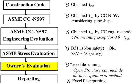
Fig. 1 shows the structure and evaluation procedure of PiTEP® program. Program structure is composed of evaluation parts by construction code, ASME CC-N597, and owner’s evaluation methodology. Evaluation of minimum thickness, tmin, by the construction code is followed by the evaluation of allowable local thickness, taloc, by CC-N597. The owner’s evaluation methodology as a fitness-for-service assessment includes the limit load method applying to straight pipes, bends, reducers, branch connections, etc., and the fitting for fitness method applying to straight pipes and bends based on the failure load by finite element analysis.
The program was codified by FORTRAN so that new equations developed in the owner’s evaluation methodology could be easily accommodated.
Construction Code
ASME CC -N597
ASME CC -N597
Engineering Evaluation
ASME Stress Evaluation
Owner’s Evaluation
Reporting
!Obtained tmin
!Obtained talocby CC N-597 considering pipe shape
!Obtained talocby CC eng. methodology : No meaning except for 0.9 tmin !B31.1(Non safety) .OR.
ASME NC(safety) !*.exe file running
: Open Structure can include the new equation or method !Excel file reporting
Fig. 2 shows the initial screen of PiTEP®, where the engineering unit system can be selected for user’s convenience in this screen.
Figure 2. Initial screen of PiTEP®
3.3
Details of the program
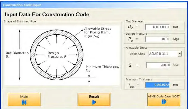
3.3.1 Evaluation based on ASME construction code
The minimum required wall thickness (tmin) can be determined by equation (2).
) (
2 min
D o D
yP S
D P t
+
= (2)
where,
tmin = minimum required wall thickness, inch (mm)
PD = design pressure, psi (MPa)
Do = outside diameter of pipe, inch (mm)
S = maximum allowable stress for the material at the design temperature, psi (MPa)
y = coefficient having a value of 0.4
Fig.3 shows the screen to obtain the minimum required wall thickness tmin calculated from equation (2) using the data typed in the screen.
Figure 3. Screen to obtain the minimum required wall thickness based on ASME construction code
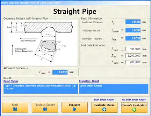
3.3.2 Evaluation based on ASME Code Case N-597
described in CC-N597 is recommended to perform. Fig. 4 shows the example screen of straight pipe selected with some thickness data. Since the CC-N597 does not provide the evaluation method for branch connection, however, PiTEP® is programmed to move directly to owner’s evaluation screen when branch connection is selected.
Figure 4. Example of selected pipe shape with comparison result of thickness criterion
(1) Comparison with thickness criteria
As mentioned earlier, the predicted wall thickness, tp at next inspection is calculated and compared with the thickness criteria in CC-N597, 0.875tnom, tmin, 0.9tmin, and tcut-off to determine the next evaluation step. Here,
tnom is the nominal pipe thickness and tcut-off is the wall thickness (normally 0.2~0.3tnom). In case of tp < tcut-off, the piping should be immediately repaired or replaced. In case of tp > 0.875tnom, the piping is as-is accepted in service. In case of tcut-off≤tp < 0.875tnom, it depends on the thickness value whether additional engineering evaluation is required before the stress evaluation according to CC-N597. If the additional engineering evaluation is not required (when 0.9tmin≤tp < 0.875tnom), users can move to stress evaluation stage directly.
(2) Engineering evaluation based on CC-N597
In case of tcut-off ≤ tp < 0.9tmin, the engineering evaluation based on CC-N597 should be additionally performed. In the additional engineering evaluation, the predicted wall thickness tp is compared with allowable local thickness taloc which can be obtained from somewhat complicated mathematical equations for straight pipes, elbows (or bends) and reducers (CC-N597). For the purpose, the defect configuration and piping geometries are inputted in the evaluation screen. Figures 5~7 show the example screens to calculate allowable local thickness for a straight pipe, an elbow (or bend) and a reducer. If tp > taloc, users can move to next stress evaluation stage. Otherwise, the piping is recommended to repair or replace.
Figure 6. Calculation of allowable local thickness for elbow based on ASME CC-N597
Figure 7. Calculation of allowable local thickness for reducer based on ASME CC-N597
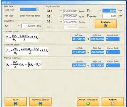
(3) Stress evaluation based on construction code
Once the thickness criteria are satisfied in the previous stage, the stress evaluation is performed in the next step. The stresses are calculated based on the construction code pertinent to safety class rather than the method suggested in ASME CC-N597. In the stress calculation, it is assumed that the circumference of piping is uniformly thinned with the predicted maximum depth. Applied loads (moments) exerted on the piping used for stresses evaluation in Fig. 8 must be provided from stress report written in plant design stage. In case that the moments do not exist, users should skip this stage and move to the owner’s evaluation screen.
3.3.3 Owner’s evaluation (Fitness-for-service evaluation)
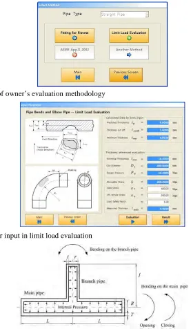
Although ASME CC-N597 is the most powerful tool for the integrity evaluation of thinned piping, there are still some vague points and limitations. For instance, the stress indices and stress intensification factors for the thinned piping are not clearly defined. In addition, there is no evaluation method provided for the branch connections. We developed our own integrity evaluation methodology (a kind of fitness-for-service assessment) to supplement the code case (Kimbet al., 2003, Park et al., 2006). Users can select one of two evaluation methods as shown in Figure 9 such as; a fitting for fitness method (curve fitting method) for straight pipes and elbows or a limit load evaluation method for straight pipes, elbows, reducers and branch connections. Figure 10 shows the example screen for input in the limit load method, where the additional information such as yield strength, fracture strength, safety factor, etc., should be typed in. The unknown design moment is assumed to be the maximum moment in case of no residual margin. The developed limit load evaluation method is also applicable to branch connections with defects in main pipe and/or branch pipe, regardless of existence of reinforcements. Input variables for branch connection are shown in Fig. 11. Figure 12 shows an example of final screen of owner’s evaluation results, wherein the results are provided in terms of safety ratio based on the criteria for moment (allowable moment to design moment), pressure (burst pressure to applied pressure) and thickness (predicted thickness to allowable local thickness).
Figure 9. Selection of owner’s evaluation methodology
Figure 10. Screen for input in limit load evaluation
Figure 12. Owner’s evaluation result screen
3.4
Program verification by comparison with mock-up test
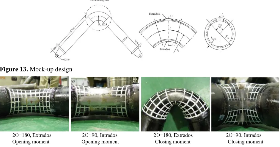
To verify the appropriateness of the integrity evaluation using PiTEP®, the results from PiTEP® was compared with the mock-up test results for elbows. Data of the elbow used for comparison are as follows:
- Nominal thickness (tnom): 8.56 mm - Outside diameter (OD): 114.3 mm - Pressure: 10.0MPa
- Allowable stress (S): 103.4 MPa - Yield strength: 288 MPa
- Limit strength: 551 MPa - Radius of curvature: 152.4 mm - Minimum thickness: 4 mm
- Thinned length to axial direction: 71.438 mm (intrados/open), 157.162 mm (extrados/close) - Thinned length to radial direction: 89.771 mm (
2 =90, open and close)
Total 24 elbow specimens having defects of various sizes and locations (intrados/extrados) were prepared as shown in Fig. 13. Elbows deformed after mock-up test were shown in Fig. 14.
Figure 13. Mock-up design
2 =180, Extrados 2 =90, Intrados 2 =180, Extrados 2 =90, Intrados Opening moment Opening moment Closing moment Closing moment
Figure 14. Elbows deformed in mock-up tests
17.5kN-m) is more conservative by about 12 ~ 37% than those (about 20 kN-17.5kN-m) of the mock-up test. For comparison, the maximum applicable moment based on the elastic theory in plant design stage was estimated (9.3 kN-m, bar of most right-hand in Fig. 14). The maximum applicable moment was found to have excessive conservatism of about 53%. Therefore, it can be said that we can use PiTEP® for the integrity evaluation of thinned piping because the program can give us proper results with tolerable conservatism.
Fig. 16 illustrates the comparison of thicknesses obtained from CC-N597 and owner’s evaluation methodology used in PiTEP®. Since the measured thickness (or predicted at next inspection) is larger than the cut-off thickness but smaller than the thickness criterion (0.9tmin) in CC-N597, the allowable local thicknesses, taloc, should be calculated from the engineering evaluation method in CC-N597. As the measured thickness was found to be smaller than taloc (in this case, 0.899 tmin), the elbow might be recommended to repair or replace according to CC-N597.
PiTEP® was used for the case as owner’s evaluation method to reduce the excessive conservatism in CC-N597. The minimum thicknesses calculated from the limit load method and the fitting for fitness method in PiTEP® are shown in Fig. 16 (two bars of most right-hand). Even with the measured thickness (4mm) smaller than criterion of 0.9 tmin in CC-N597 (4.75mm), it can be said that the elbow has some safety margin of 2.4 (limit load method) ~ 4.4(fitting for fitness method) and that structural integrity of the elbow is confirmed until next inspection date.
19.89 20.3 12.415 17.5 9.292 0 5 10 15 20 25 30 Exp_Failure M (Open) Exp_Failure M (Close)
Failure M by Limit Load
Failure M by Fitting for Fitness Max. Applied Design M Fa ilu re M om en t ( kN -m )
Experiment and Estimation Elbow Failure Moment
Figure 15. Comparison of elbow failure moments
7.8 5.278 4.75 4 2.34 1.657 0.902 0 1 2 3 4 5 6 7 8 9
No rminal Minimum CC -N597 Measured Cut -o ff PiTEP (Limit Lo ad )
PiTEP (Fitting fo r
Fitness) Thickness Evaluation Method
Comparison of Pipe Thickness
Current Thickness Guide
Figure 16. Comparison of elbow wall thicknesses
4
CONCLUSION
- Integrity evaluation of all kinds of piping such as straight pipe, elbow, reducer, and branch connection is possible. Users can overcome the limitation of ASME CC-N597.
- Owner’s method in PiTEP® was confirmed to have enough conservatism by verification test using mock-ups. It is possible for users to do optimal integrity evaluation.
- As PiTEP® is designed in user-friendly environment, users can easily access it only with piping configuration, measured thickness data and basic operating parameters.
REFERENCES
ASMEa, ASME B&PV Code Sec.III, 1995 ed., Nuclear Components
ASMEb, ANSI/ASME B31.1, 1995ed., Power Piping Code
ASMEc, ASME B&PV Sec.XI., 1995ed., Rules for Inservice Inspection of NPP Components
ASME, ASME B&PV Sec.XI, Div.1, 1998ed., Code Case N-597, Requirement for Analytical Evaluation of Pipe Wall Thinning
Chexal, B., Horowitz, J., Dooley, B., Millett, P., Wood, C., and Jones, R., 1998, Flow-Accelerated Corrosion in Power Plant, EPRI/TR-106611-R2
Gerber, T.L., Riccardella, P.C., Kuo, A.Y., and Pitcairn, D.R., 1988, Acceptance Criteria for Structural Evaluation of Erosion-Corrosion Thinning in Carbon Steel Piping, EPRI NP-5911SP
KHNP, 2003, Management Program for Thinned Pipe in Nuclear Power Plants Secondary System (in Korean)
KHNP, 2008, Optimization of Thinned Pipe Management Program and Application (in Korean)
Kim, J.W., Park, C.Y., and Kim, B.N., 2001, Evaluation of Local Wall Thickness of Thinned Pipe Subjected to Internal Pressure and Bending Moment, Trans. of KSME(A), Vol. 25, No. 1, P. 81-88 (in Korean)
Kima, J.W. and Park, C.Y., 2003, Effect of Length of Thinning Area on the Failure Behavior of Carbon Steel Pipe Containing a Defect of Wall Thinning, Nuclear Engineering and Design, Vol. 220, P. 274-284
Kimb, J.W., Park, C.Y. and Kim, Y.J., 2003, Status of ASME Code for Integrity Evaluation of Wall Thinning Defect in the Nuclear Piping, Annual Fall Meeting of KSME, Vol.A (in Korean)
Lee, J.K., Park, C.Y., Lee, S.H., Park, S.K. and Lee, Y.S., 2005, Comparison of Evaluation Criteria of the Thinned Pipes by Wall Thickness from the Measurement Data, Annual Fall Meeting of KSME, Vol.A, P. 514-519 (in Korean)
Miyazaki, K., Kanno, S., Ishiwata, M., Hasegawa, K., Ahn, S. H., and Ando, K., 1999, Fracture Behavior of Carbon Steel Pipe with Local Wall Thinning Subjected to Bending Load, Nucl. Eng. & Des, Vol. 191, P. 195-204
Oh, C.S., Kim, Y.J. and Park, C.Y., 2007, Plastic Loads of Elbows with Local Wall Thinning under In-plane Bending, International Journal of Fracture, Vol.145, P.63-79
Park, C.Y., Lee, S.H., Kim, T.R., Park, S.K. and Kim, J.W., 2005, Development Strategy and Status of Industrial Code and Standard for Integrity Evaluation of Wall Thinned Pipes, Transactions of the Korean Society of Pressure Vessel and Piping, Vol.1, No.1, P.55-63