University of Windsor University of Windsor
Scholarship at UWindsor
Scholarship at UWindsor
Electronic Theses and Dissertations Theses, Dissertations, and Major Papers
7-17-1969
Structural properties of corrugated sheets used in cylindrical
Structural properties of corrugated sheets used in cylindrical
shells.
shells.
M. N. El-Atrouzy
University of Windsor
Follow this and additional works at: https://scholar.uwindsor.ca/etd
Recommended Citation Recommended Citation
El-Atrouzy, M. N., "Structural properties of corrugated sheets used in cylindrical shells." (1969). Electronic Theses and Dissertations. 6551.
https://scholar.uwindsor.ca/etd/6551
This online database contains the full-text of PhD dissertations and Masters’ theses of University of Windsor students from 1954 forward. These documents are made available for personal study and research purposes only, in accordance with the Canadian Copyright Act and the Creative Commons license—CC BY-NC-ND (Attribution, Non-Commercial, No Derivative Works). Under this license, works must always be attributed to the copyright holder (original author), cannot be used for any commercial purposes, and may not be altered. Any other use would require the permission of the copyright holder. Students may inquire about withdrawing their dissertation and/or thesis from this database. For additional inquiries, please contact the repository administrator via email
INFORMATION TO USERS
This manuscript has been reproduced from the microfilm master. UMI films
the text directly from the original or copy submitted. Thus, some thesis and
dissertation copies are in typewriter face, while others may be from any type of
computer printer.
T h e quality of this reproduction is depen d en t upon the quality of the
co p y submitted. Broken or indistinct print, colored or poor quality illustrations
and photographs, print bleedthrough, substandard margins, and improper
alignment can adversely affect reproduction.
In the unlikely event that the author did not send UMI a complete manuscript
and there are missing pages, these will be noted. Also, if unauthorized
copyright material had to be removed, a note will indicate the deletion.
Oversize materials (e.g., maps, drawings, charts) are reproduced by
sectioning the original, beginning at the upper left-hand corner and continuing
from left to right in equal sections with small overlaps.
ProQuest Information and Learning
STRUCTURAL PROPERTIES OP CORRUGATED
SHEETS USED IN CYLINDRICAL SHELLS.
A Thesis
submitted to the Faculty of Graduate Studies through the Department of Civil Engineering in Partial Fulfilment of the Requirements
for the Degree of Master of Applied • Science at the University of
Windsor.
by
M.N. EL-Atrouzy
UMI Number:EC52733
®
UMI
UMI Microform EC52733
Copyright 2007 by ProQuest Information and Learning Company. All rights reserved. This microform edition is protected against
unauthorized copying under Title 17, United States Code.
ProQuest Information and Learning Company 789 East Eisenhower Parkway
ABSTRACT
The study on corrugated sheets made up to date is
oriented towards plane sheets, used for clading
and folded plate roofs. However, it is generally
recognized that shells have better load carrying
characteristics since they transfer the applied
loads mainly into forces in the plane of their
surfaces.- This thesis is mainly concerned with
establishing the mechanical properties of the cor
rugated sheets to be used as a basis for the theo
retical analysis of shells.
Particular attention is paid to the shear behaviour
as it is a governing factor in such shells. Experiment
al and theoretical investigation is carried out to
determine the modulus of rigidity ( G, ) of the plane
and curved shear diaphragm. Also the critical buck
ling load for plane and curved panels is tested ex
perimentally .
The comparison between plane and curved corrugated
sheets proved that although the load-deflection b e
haviour under shear loading is the same, yet the u l
timate load for the curved sheets is higher than for
the plane ones.
The apparent strain rigidity (Ex) of the corrugated
sheets in direction lateral to corrugations is found
experimentally to be = 0.004 E.
The buckling load for the plane diaphragm obtained
experimentally proved to be in good agreement with
the theoretical results given by Seydel (17); this
leads to accept the bending and torsional rigidities
ACKNOWLEDGEMENTS
The Candidate wishes to express his gratitude to
Dr. G. Abdel-Sayed, for his valuable guidance,
advice and patience during the preparation of this
Thesis.
The Candidate owes a great thankfulness to the
Technicians, Mr. G. Michalczuk and Mr. P. Feimer
for their assistance in the experimental work.
This research study was made possible through fin
ancial assistance obtained from the N.R.C. of Canada.
The material for experimental work received free from
WESTEEL ROSCO LTD. is greatly appreciated.
CONTENTS
ABSTRACT iii
ACKNOWLEDGEMENTS V
TABLE OF CONTENTS vi
LIST OF FIGURES vii
LIST OF TABLES viii
NOMENCLATURE ix
CHAPTERS:
I INTRODUCTION 1
II PARAMETERS AFFECTING THE SHEAR BEHAVIOUR AND
STRENGTH OF CORRUGATED SHEETINGS. . 4
Ill THE SHEAR MODULUS OF CORRUGATED SHEETS PRO
POSED FOR USE IN SHELLS. 18
IV EXPERIMENTAL EVALUATION OF THE SHEAR
STRENGTH OF CURVED CORRUGATED SHEET PANELS 31
V DETERMINATION OF THE APPARENT STRAIN RIGIDITY OF THE TRANSVERSE DIRECTION OF CORRUGATED
SHEETS "E*". ■36
VI OBSERVATIONS, CONCLUSIONS AND RECOMMENDATIONS 43
APPENDICES 48
A: Bending and Torsional Rigidities; B: Moment of inertia of Corrugated sheets; C: Determin ation of the elastic movement per bolt under unit load between the sheet and edge member; D: The critical shear load of corrugated sheets.
TABLES AND FIGURES 67
FIGURES
Figure Page
(C) Load-slip curve 63
3.1 Tension test assembly to find the value
of " S f". 77
3.2 Shape of tearing around bolts. 78
3.3 General layout of plane shear diaphragm
of experiment No. (1). 79
3.4 Load-deflection curves of the plane dia- . phragm with and without the effect of
rigidity of edge members. 80
4.1 General layout of an experiment on
cylindrically curved shell roof. 81
4.2 Load-deflection curves of the cylindrical shell of experiment No. (2) with and w i t h out the effect of rigidity of edge members.82
4.3 Mode of tearing around bolts near the
corner in the second experiment. 83
4.4 Load-deflection curves of the cylindrical shell of experiment No. (3) with and w i t h out the effect of rigidity of edge members.84
5.0 Tension test assembly on corrugated sheets.85
(5.1,2,3) Stress-strain curve of corrugated sheets when pulled in the weak direction. 86-88
TABLES
Table Page
3.1 Dial readings of Experiment No. (1) 68
3.2 Analysis of test results of table 3.1 69
4.1 Dial readings of Experiment No. (2) 70
4.2,3 Analysis of test results of table 4.1 71
4.4 Dial readings of third experiment 72
(4.5,6) Analysis of test results of table 4.4 72-73
corrug-NOMENCLATURE
d
= cross-sectional area.a = length along transversal direction of unit
shear panel
= length along applied shearing force.
h
= developed length of corrugation.ke -
effective width of corrugated sheets.Bx-
Bending rigidity in the x-direction.By-
Bending rigidity in the y-direction.H
= Apparent torsional rigidity.Px
= Axial rigidity in the x-direction.Dy
= Axial rigidity in the y-direction.DXJ -
Shear rigidity in the x-y plane.£* = Apparent strain rigidity in the x-direction.
=
Eccentricity at distance x.£yz
:f= Modulus of elasticity in the y-direction ='Estee/
■P
= maximum eccentricity at the corrugation pealc.G =
Modulus of rigidity.Q'=
Shear stiffness per unit lengtli =Qy .t
0 =
girth of one corrugation.1 = moment of inertia per unit length.
=
a constant depending on diaphragm cross-sectionshape and the end fastener spacing (in)
£
= length o£ member.P
= Applied load.sp
= pitch of fasteners along the transversaldirection.
Q
= Shearing force.Sf
= Displacement under unit load per bolt betweenthe sheet and the edge member.
-5^ = Displacement under unit load per bolt due to
seam slip between sheets.
t
= thickness of corrugated sheet.V = Strain energy of element.
x,y,z =
Cartesian coordinate.X
= Shearing strain.7 ^ = Shearing stress.
P
= Poisson’s ratio.= Shear deflection.
/
^ = deflection per unit shearing force.
&
= deflection due to the effective width indirection of applied shearing force Q.
<^r= deflection in direction of shearing force Q
due to flexibility of transversal edge
INTRODUCTION
Research done on the capacity of floors and roofs com
posed of light gauge steel panels to resist loads in
their own planes, has opened the way to new uses of
light gauge panels in weight saving building systems.
Floor and roof decking has been used to provide resist
ance to wind and seismic forces, and light steel panels
are used for the shear diaphragms in folded plate
roofs. In all these cases, design information has
been based on the results of full scale tests carried
out to determine the shear behaviour of complete plane
panels. Recently a method has been proposed whereby
the shear stiffness of plane roof panels, complete with
sheeting, fasteners, purlins and connections, can be
estimated. This method consists of determining the
flexibility of each component and summing the separate
effects.
The study made up to date is oriented towards plane
sheets, of prismatic or corrugated sections, used for
clading and folded plate roofs. However, it is gener
ally recognized that shell roofs have better load
carrying characteristics since they transfer the applied
loads into mainly forces in the plane of their surfaces.
On the other hand, corrugated sheets can be produced
with cylindrical curvature and are already being used,
without precise method of analysis, in farm buildings.
The object of this work is to study the properties of
the corrugated sheets proposed for use in cylindrical
shell roofs, and to establish the missing data for.
their analysis and design.
Each element of a shell is subject, in general, to
bending moments, torsion, shear and axial forces. Thus
in order to analyse a shell of corrugated sheets, the
bending, torsional, shear and axial rigidities of the
sheet should first be found.
These
are:-Bx : Bending rigidity in the x-direction.
By
'
•
Bending rigidity in the y-direction.H : Apparent torsional rigidity.
Dx : Axial rigidity in the x-direction.
Dy : Axial rigidity in the y-direction.
Dxy : Shear rigidity in the x-y plane.
In presenting his theory of bending of orthotropic
plates, Huber (9) suggested treating the corrugated
sheets as orthotropic plate. He also proposed the ex
pressions for bending and torsional rigidities which
are represented in "APPENDIX A".
When loaded in its plane, the behaviour of a plate is
rigidity.
Dxy
, is dependent on several variablesincluding panel configuration, type and spacing of
fasteners, panel length, cover width and material
strength.
A discussion of these variables, which have been
under investigation since 1955, is presented in
chapter (II). Chapter (III) deals with the theo
retical and experimental evaluation of the shear
rigidity of the corrugated sheets suggested for
application in cylindrical shells. The effect of
the curvature of the corrugated sheets on the shear
behaviour is examined experimentally and presented
in chapter (IV). The'axial rigidity,
Dy
, in thedirection of corrugation "figure (16)", is equal to
the thickness times E. Dx is evaluated experiment
ally and presented in chapter (V).
CHAPTER II
PARAMETERS AFFECTING THE SHEAR BEHAVIOUR AND
STRENGTH OF CORRUGATED SHEETINGS.
Diaphragm response to loads acting in its plane is
dependent on several variables including panel con
figuration, type and spacing of fasteners, panel
length, cover width, material strength and size of
supporting frame. Full scale tests have been carr
ied out to determine the effect of each factor on
the behaviour and ultimate strength of 'the shear
diaphragms. Recently, a theoretical approach has
been proposed to determine the shear flexibility C7) •
However, it requires experimental evaluation of part
icular constants depending on the corrugation con
figuration and the type of fasteners used.
In the following, for each parameter, both load-
deflection behaviour and the ultimate strength of
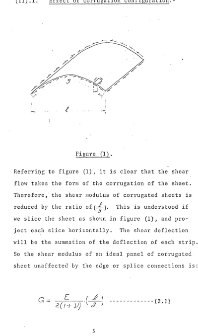
(II)*1* Effect of corrugation
configuration:-Figure (1).
Referring to figure (1), it is clear that the shear
flow takes the form of the corrugation of the sheet.
Therefore, the shear modulus of corrugated sheets is
reduced by the ratio of (-^-). This is understood if
we slice the sheet as shown in figure (1), and pro
ject each slice horizontally. The shear deflection
will be the summation of the deflection of each strip.
So the shear modulus of an ideal panel of corrugated
sheet unaffected by the edge or splice connections is:
(II).2. Effect of method and spacing of c o n n e c t i o n s
:-Whether it is a sheet-to-sheet or sheet-to-frame con
nection, the method could be welding, bolting, gluing
or using screws. Gluing would have been the best
method of connection as it transmits the shear flow
smoothly between the connected sheets. The effect of
gluing can be studied experimentally, yet it is im
practical. The most practical methods are using bolts
or screws. Experimental data are always required in
order to establish the effect of the type and spacing
of connections.
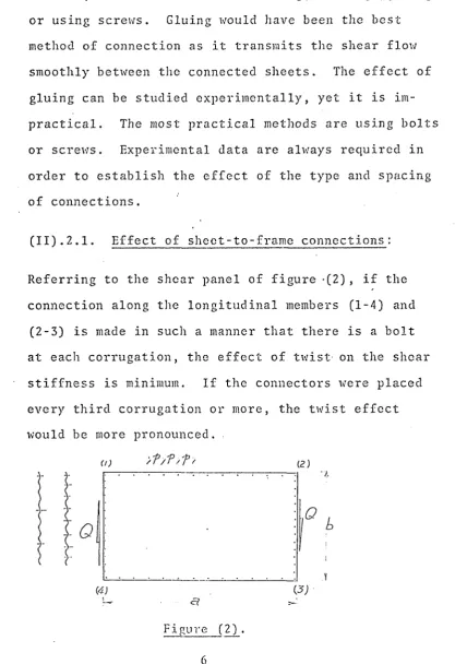
(II) .2.1. Effect of sheet-to-frame connections:
Referring to the shear panel of figure -(2) , if the
connection along the longitudinal members (1-4) and
(2-3) is made in such a manner that there is a bolt
at each corrugation, the effect of twist on the shear
stiffness is minimum. If the connectors were placed
every third corrugation or more, the twist effect
would be more pronounced. ■
- - • - <=?
Q
Bryan (7), in predicting this effect on the shear
flexibility, gave experimental values of some con
stants for connections at every corrugation and at
every third corrugation for the case of prismatic
sections.
Referring to the same figure, the shear displace
ment is affected by the slip at the connections along
(1-4) and (3-2). Assuming the pitch of the bolts
along (1-2) and (3-4) to be
"f
" , and the displacement at each bolt under unit load to be
uSp",
thework done by one bolt i s :
2
b r \ b
)
So that the strain energy of all the bolts "V" can
be written in the following expression:
V =
X No. of bolts in the two2
transversal members.Applying Castigliano’s theorem:
T
W
= S f
...C 2 ' 2 )where is the deflection in the direction of
"Q"
due to slip between the sheets and the transversal
edge members.
'9 V _ ^
x zjr*2)
__Q.p x a x
2
9(2
b*
■ £ -
2
a Sp Q_£_
(2i3)*
L*
u-^ti fs ^-0 found experimentally for the sheets
and connectors in hand.
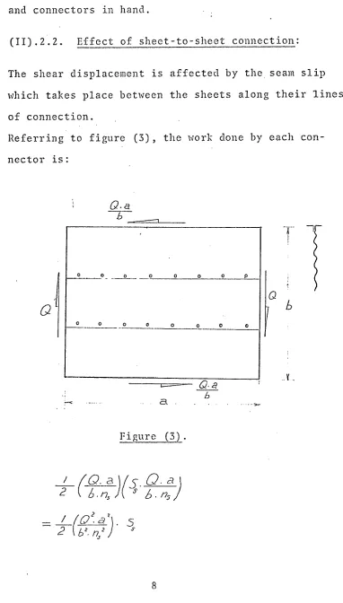
(II). 2. 2. Effect of sheet-to-sheet connection:
The shear displacement is affected by the seam slip
which takes place between the sheets along their lines
of connection.
Referring to figure (3), the work done by each con
nector i s :
Q ■
a.
bT ~ T
Q
b
..Y
G a
b
w here:
n
si,. =n c
displacement at each connector
under unit load.
number of sheets.
number of fasteners (connectors)
in each side lap.
Thus, the strain energy of the connectors of the
whole installation is:
V = / J (n i) ■ n
p / z z sn s
c b ns
Applying Castigliano1s theorem as before:
'
~SV
=
(nsA - 0 Ss Q
dQ ns ■ b z
(2.4)
p ' tf \
where "o5 " is the deflection in the direction of
Q
due to the seam slip between the sheets.
(II).3. Effect of flexibility of edge members :
-Q
Q
i
I a
L - 2 3
(a)
e / n a r C S S /pri
'^"s/on.
Figure (4
-a)
shows a diagramatic sketch of the h orizontal plane diaphragm tested in. this programme. .
Figure (4-b) shows one half of the diaphragm which
represents an elementary shear panel. The axial
force in the transversal members (edge members along
the x-direction) is assumed to increase linearly
from zero to
Q
-— , so that the force "I
*" at anyb
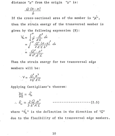
distance
"x"
from the origin”o"
is:Q
(
sl-
x)
L
/ If the cross-sectional area of the member is "y\">
then the strain energy of the transversal member is
given by the following expression (7 ):
ra
n zVr.= j
-J-
d*
4 ^ A E t=
r
(a~x) j*
4
ZA'Eb
1
€ ^ A 'E
Then the strain energy for two transversal edge
members will be:
V =
d.
a
3
3 i / A ' E
Applying Castigliano's theorem:
3 Q tr
£ =
E.Q
s3
(2 .5)3
k?A’E
where
"&t"
is the deflection in the direction of "«Q"It is clear from equation (2.5) that the more the
rigidity of edge members, the less the effect on the
deflection. If the transversal edge members are
assumed to be infinitely rigid (A' E =oc ), they have
zero strain energy and
6
tr
tends to zero. If practicaledge members (flexible) are used, their strain energy
should be taken into account.
(II).4 Effect of Diaphragm dimensions:
One of the results of the Cornell (12) tests, was the
/
relation between shear stiffness
G
(lb/in) and panellength. Several tests were carried on 26 gauge stand
ard corrugated diaphragms with panel length being the
variable. The following equation was used to
calcul-/
ate the value of
G
:g =
-i + » ) 2 A 's _
A
£
. (L t)!Jwhere:
Kz =
a constant depending on diaphragm(
2
.
6
)
cross-section, shape and the fastener (in) £
E
= modulus of elasticity of steel 29.5x10t
oS,
G =
Shear stiffness (lb/in)£ '= Uncoated thickness of corrugated panel (in
V = Poisson’s ratio (0.3)
A
= Corrugated pitch (in) "see figure below"$
= Girth of one complete corrugation (in)"see figure below"
L
= Length of panels from center to centerof end fasteners, measured parrallel
This equation was used after calculating the values
of the constant from the results of full scale
/
tests by putting the known " G " into the equation and
solving for . This value was substituted back in
to the equation, and by allowing the length to vary,
t
the curve for
G
versus length of panel was plotted./
There is a wax. value for
G
controlled_by the shearmodulus of the material itself. Using the same
eq-/
uation and substituting for the length by oc-, C? will
b e :
G
'=E t
■.A-
=211, 00 0
lb
An-Z O + V )
2
'
( P -
0.3
, E -
30
x
1
o 6 ps
1
; t=
0
0173
E£EL )
v ^
'
/ 2.8/5 '
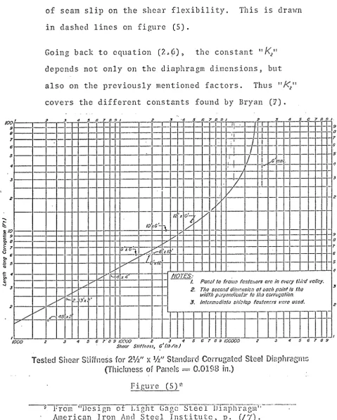
This relation is shown in figure (S). When using
this curve, care should be taken to retain the same
type and layout of fasteners.
The equation of G is identical to equation (2.1}
which is the value of
"Q"
for a corrugated sheetL en g th al on g C o rr u g a ti o n (F t )
be explained, because the twist effect is minimized
when the length
"L"
in infinite. The last part ofthe curve should be corrected to allow for the effect
of seam slip on the shear flexibility. This is drawn
in dashed lines on figure (5).
Going back to equation (2*6), the constant "
K?"
depends not only on the diaphragm dimensions, but
also on the previously mentioned factors. Thus
covers the different constants found by Bryan (7).
!
1
? > ft t_j
II • — 1
I — - — — -
-'1 i
-, I
i 1
-' 1
1 i 11
-1
r | L 1 ,G' TiOi
-/ i ui
1 / I
. / i -/ >
V
/-10 tG — 12 ' X
s o'— i / > -— -— y s's'
— 1s-6 'xU
- ' / , t
-4 x -4 ‘
- NOTES:1. Panel to frame fcsfenors arc in every third valley.
2. Tho second dimension a t oach point Is tiis width perpendicular to tha corrugation. 3. intermediate sidetop fasteners v:cro used.
- -
-
-a,. S3'x.>*
4 8
'/O O O 2 .3 4 5 6 7 0 9 IOOOO 2 j 4 S C 7 B 9 IOOOOO 2 3 4 S 6 7 0 3
Shear Stiffnesst c ‘ ( l b / i n )
Tested Shear Stiffness for 2
lh"
xV?."
Standard Corrugated Stee! Diaphragms (Thickness of Panels — 0.0198 in.)Figure
(5):-?"'From'" "Design of Light Gage Stee 1 Diaphragm1' • American Iron And Steel Institute, p. (/7) .
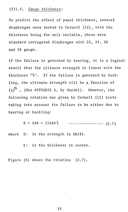
(II).5. Gauge t h i ckness:
To predict the effect of panel thickness, several
diaphragms were tested in Cornell (12) , with the
thickness being the only variable, these were
standard corrugated diaphragms with 22, 24, 26
and 28 gauge.
If the failure is governed by tearing, it is a logical
result that the ultimate strength is linear with the
thickness "t". If the failure is governed by buck
ling, the ultimate strength will be a function of
(t)% , (See APPENDIX A, by Seydel). However, the
following relation was given by Cornell (12) tests
taking into account the failure to be either due to
tearing or buckling:
S = 140 + 11560 t ... (2 .7)
where S: is the strength in lb/ft.
t : is the thickness in inches.
6 0 0
n; 5 0 0
£ 4 0 0
o>
to
3 0 0
200
S = 140 + Il5 6 0 t
100
0.005 0.010 0.015 0.020 0.025 0.030 Thickness in Inches
Strength variation with thickness
of standard corrugated Diaphragms.
Figure (6)*
(II).6 . Effect of curvature:
From the above given analysis of the different factors
affecting the shear rigidity of plane sheets, it is
believed that the curvature of the corrugated panels
* From "SFFength ancFUel
i
aviFur~~oF*TTgEt-gage-steel shear diaphragms" Cornel] Engineering Research 'Bulletin 67-1, by Larry D. Luttrell.does not affect the load-deflection curve (i.e. the
shear behaviour is the same for plane and curved sheets).
This is true especially if the connections with the
longitudinal members (1-4 fj 2-4 in figure (2)) are
made in such a manner that there is a connector at
each corrugation, otherwise, slight difference may
take place because of the different magnitude of
twist along the edges for the plane and curved sheets.
The effect of curvature on the shear strength (ultimate
load) can be established by comparing the ultimate
load of plane and curved isotropic plates. Batdorf (4)
and others gave the following expression for the crit
ical shear stress of the curved isotropic plates:
(
2.
8)
b .t
where: = width of plate measured along arc.
t
= thickness of plate.• -£> = flexural stiffness of plate per
unit length =
E
= Young’s modulus of elasticity.= critical-shear-stress coefficient.
= critical shear stress.
V
= Poisson’s ratioo tl •
The value of changes proportionally with a cur
vature parameter 2 "which depends on the dimension
2 = 7 ^ / ' - ^ (2 .0)
where
"r"
is the radius of curvature of the plate.As "z" increases (i.e.
r
decreases),K
, also increases and consequently the critical shear stress
increases. So the greater the curvature, the high
er the critical shear stress. This result in the
case of isotropic material can be thought to be
correct for the case of orthotropic material, which
(to the knowledge of the Candidate) has not been
treated theoretically.
The experiments done by the Candidate on curved
sheets, proved that the critical shear load of the
curved panels is much higher than in the case of a
plane diaphragm, therefore conforming to the prev
ious discussion. These experiments will be present
ed in chapter (IV).
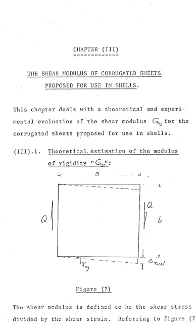
CHAPTER (III)
THE SHEAR MODULUS OF CORRUGATED SHEETS
PROPOSED FOR USE IN SHELLS.
This chapter deals with a theoretical and experi
mental evaluation of the shear modulus
GiXJ/
for th<corrugated sheets proposed for use in shells.
(111).1. Theoretical-estimation of the modulus
of rigidity "
G
x " :L r
a
JQ
A
..V
^tal
Figure (7)
The shear modulus is defined to be the shear stress
V'
shear stress = y j - ; shear strain =
dXj
(in radians) = —G
=.Q '
aV
U . A nui
If the deflection " is given per unit load (^f = A )
then:
G -
— - — — .---(3.1)^
tt-Ku,/
/
The value of "
^ t"
,
may be considered to be composedof the following:
where: 4^. = displacement due to sheet-to-frame
connection under unit load.
/
= displacement due to seam slip between
sheets under unit load.
/
A si =
shear deflection of ideal sheetingunder unit load.
Here, we are interested in the shear stiffness of the
corrugated sheets, thus the deformation of the edge
members are not to be encountered, also the effect of
twist at the edge of corrugation is eliminated by
having a bolt at each corrugation.
(III).1.1. Displacement due to connections between
sheets and transversal edge members:
In chapter (II), the deflection due to connectors
between sheets and transversal members is given by
equation (2.3)i . Several tests were made on the
material in hand to find the value of
"S^,".
Thebolts used were of 5/16" diameter, and 1" long with
neoprane washers. The test assembly was inserted
in a tension machine and an increasing load applied
up to failure. The average movement at the sheet
connectors, including a negligible- amount of sheet
extension, was measured by a pair of dial gauges.
The value of slip is variable with the load.
Small loading is transfered by friction; by in
creasing the load, sliding starts to take place
leading to ;lower value of "•5r". Up to a limit when
the bolts bear against the sheet, the value of "5^"
starts to increase. versus load per bolt is
given in figure (C). Although no work was done
on sheets of other thicknesses, it is reasonable to
assume that the slip is inversely proportional to
the sheet thickness
" t
" (i.e.):s/r
A
) = sf<^«»x±sr z
'*■/■''¥
- (3 -3)The ultimate load per bolt was found to be 1.6 kips.
One test arrangement is shown in figure (3.1) and
sheet failure which took place by tearing is shown
in figure (3.2). The curves and analysis of the
slip is given in "APPENDIX C". Referring back to
equation (2.3) and assuming the displacement per
unit load:
V =
2 $ 5? r
(3 .4)(III).1.2. Displacement due to seam slip between sheets:
The displacement due to seam slip is explained in section (11.2.2.),
and is given by equation (2.4), assuming the displacement per unit
load:
/ _ ( f I s A . — t ) g a O ' * / h ' p ) . . ---(3-5)
* --- 7?;— ‘ ^
be
Referring to Figure (c) , the value of 55 is equal to the value
// tt
of Sj, in the range of friction. For the range of bearing, the
"c “ "o ” .
value of Dj could be taken as double the value of since
the movement here will be due to two movements of the sheeting.
(III).1.3. Shear deformation of ideal sheet under unit load:
t Referring to equation (3.1), and solving for A :
^ =
b.t.G'-
--- --- (3-7)(G is the modulus of rigidity for an ideal sheeting without any
connections between panels (which is impossible in practice) and
with an infinitely long panel (<9=oc>). The theoretical value of
G
is given by equation (2.1).
¥
Substituting for
G
in equation (3.7)A ' = ( 3 .8)
b . t ■ E J? K
Substituting for E and V of steel:
a
>
-7 a
-A S n =
O-92X10
b . t
By substituting equations (3.4), (3.5), (3.9) in
equation (3.1), the value of
"Gx"
can be calculated.A comparison of the theoretical method with the ex
perimental result follows in page (27).
(III).2. Experimental evaluation of the shear
modulus
"Gxy":
The behaviour of corrugated steel sheet panels in
shear does not yield nicely to pure theoretical an
alysis. This is because of the large number of
parameters involved. Therefore, full scale tests
are needed to test the results obtained by the theo
retical analysis. Tests were carried out in the Civil
Engineering Laboratory at the University of Windsor,
in order to determine the modulus of rigidity of a
shear panel and to predict the shear behaviour in
corrugated shells.
(III).2.1. Description of the testing apparatus,
the instrumention and procedure of
testing:
The general layout of the first experiment is shown
in figure (3.3). Referring to the sketch of figure
(8), the corrugated sheets being used were of the
standard type
2-
f-X-j- > gauge 20. Two cold rolledwere used as a jacking beam, and
X /j-'CA/o)
coldrolled angles were used as longitudinal stiffeners
parallel to jacking beam. Cold rolled angles
(/A-x/£,£/}/o)
were used as transversal supports. To minimize
frictional resistance,the frame was supported by
<p
1"rollers over 6 supports located at. the ends of the
longitudinal members. The two longitudinals were
clamped (horizontally) to rigid frames.
The six corrugated sheet panels were laid as shown
in the picture of figure (3.3), and suitably inter
connected by 5/16" diameter standard bolt's to form
a horizontal shear diaphragm.
Loads were applied in increments of 200 lbs., using
a 20 ton hydraulic jack together with a Universal
testing machine, and at each increment, the horizon
tal movements of the points indicated on figure (8)
were recorded.
(III).2.2. Analysis of test results:
All readings of the mechanical dials located as
shown in the sketch of figure (8), are summarized
in TABLE (3.1). The deflection of point (12) and
point (7) are corrected by subtracting the average
of A and A^/Aand , respectively; this correct
ion is due to the extension of the longitudinal
members and is shown in TABLE (3.2).
Ad-/ ^
I
I
~2
b
T
h - 9 3 H
1
1
...
3 =:
/
2
O-a - /
j *
Figure (8)
The load-deflection curve is plotted in figure (3.4).
First the shear stiffness in "lbs/inch" is calculated
deformation of the edge members:
r ' = PL — = o.€4-5-£—
07 ^ i.A A
in the elastic range between a load of 1400 lbs. and
400 lbs. :
Q ' - 1 4 - 0 0 - 4 0 0 _ e 8 S O O lbs/in. O. 0/65Z5- O.OOH/2.
To get
Q
;n (PsOm
-G
=G'J- - £.8.500.
=1.? xto6
y
t
0.035?
(111).2.3 Shear modulus of the corrugated sheets
The shear modulus that can be considered in the
design of shells is calculated by subtracting . the
effect of deformation of the edge members. Referr
ing back to equation (2.5),
=
- 2 Q a 3_
ir
zb'A'E-This area (A7) is composed of the cross-sectional
area of the transversal beams plus the area of an
effective width of the corrugated sheets. The
effective width of the corrugated sheets can be cal
culated as follows:
b ' = b. J _ = 93 x = ?& "
J
2.€61
the ratio
GL
=7e
-0
.
4.07
23 2 x JZOThus (1) ^ = 0.3/7
b
where
L
is the effective width.Thus the effective area of the transversal stiffener
is
i
' A ' x 98 X 0.0359 + 0.3675 = 0.9085
£
Substituting for a, i ,
k'
and E in equation (2.5),"S.
" can be calculated in terms of "62" as follows:tr
S.
= 2Q
(10X12)
---4..55 %
10 ^ Q
tr
3 ( 7-75 X/2)3 (.30 8 5)30X10*The following table is arranged to determine the
deflection of a similar diaphragm with infinitely
rigid edge members (i.e.) when (
8tr-
0):Applied Load
(lbs)
Q = Y l b s .
Total Displace ment (A)inch.
£ = .00000455Q (A- t^tf. )inch
200 100 0.00450 0.00046 0.00404
600 300 0.00962 0.00138 0.00824
1000 500 0.01237 0.0023Q 0.01007
1400 700 0.01652 0.00322 0.01330
1800 900 0.02140 0.00414 0.01626
2200 1100 0.02822 0.00507 0.02315
2600 1300 0.04160 0.00600 0.03560
3000 1500 0.05900 0.00690 0.05210
3400 1700 0.12137 0.00781 0.11356
3800 1900 0.21950 0.00875 0.21075
Two load-deflect ion curves are shown in figure (3.4)
for the actual disphragm with flexible edge members
and a similar diaphragm with infinitely rigid edge
members
(S
E =00
or&tr=
0). Considering the curveafter modification (reduction of deflection due to
Si
r
) ; the shear modulus is calculated and is found6
(I II). 3. Comparison between theoretical and experi
mental
results:-The value of
Q
is calculated using equation (3.1)and is compared with the experimental results. Also
comparison is made between the calculated and observ
ed value of the ultimate shear load.
(III).3.1. Calculation of "
GX
J
r
"\-The plane diaphragm has the following properties:
a = 10^ 7.75/
ns=
13^ 3 t= 0.0359 '2-
= 2.815* 2.669' />= 10"From curve in fig.. (C) , the load per bolt = or
o.pgkiy
/ • / J A X OI F o r t h e f r i c t i o n r a n y e :
5^ = 5^)
^ ,=,0.02 in/kip §
Ss=
0.02 in/kip.-1- Deflection due to unit load because of sheet-to-
frame connector:
Using equation (3.4):
XL
=f a
--- --- - (5.4)' b
_ 2.X toX12 X 0-02 X 10
(7-75 X / a f
= 0 - 0 0 5 5 2 'n/k.f
-2- Deflection due to unit load because of seam
slip:-a ' = A
(Q
l-
zI). -fl
... ... (3.5)ns o
_ 0.02 (3-/) !QO _ 0.0051 in /Kip
13 50 x r
-3- Deflection of ideal sheet due to unit
shear-ing load:
-A = 2 a & = 2 A to (/ + 0-3) . /2-8IS- j _ 0 . O O 3 3 0
S/!
b t E j
30
X 10 s X-I-75AO-03S3 \Z-^7/
Thus the total deflection A =,
•ota!
0 .00330+. 005/+00552= .0139 2 inch/kip
From equation (3.1), the modulus of rigidity is:
_
6
Q - a - X / O O P _ 2.55 X I O f>s'
^ b . t . A ' , 7-7S X -035S X • 0/39 2
which is
/
5
x
hijher than the value found experimentally.
(III).3.2. Ultimate shear load:
It is obvious that by providing an adequate number of
bolts, failure can take place only due to buckling of
the corrugated sheets. This was the case of the ex
periment in hand.
Theoretically, the buckling shear load .in lbs/in. can
be determined according to Seydel's (17) formula:
r = r. i
/ &
b;
m
Referring to "APPENDIX D", the analytical computat
ions of the critical shear load can be as follows:
Assuming E = 30 x 10
f>si,V=
0.3 and the geomet0 . 2 . 5
' 2 c j - 2 - 8 / 5
z / = 2- e e . j
Figure (9)
B
=3
= 2 -GG"^ 3 0 M Q e ( ■ 0 3 5 3 )2 'i2(l~VZ)
2-815-
‘ /2( l
_o.32)
=
1 2 0 - 4 2 5 G
Jb. in
z
i
-0-8/
/
+ 2.-
5/ _£(0-25f (0-0359)
2
&
I _
0-8/
=
2
3.5 X IO
-s
/•/-
2.5(jZ5- f
'Z.G6J/ J
By = EL 1 =. 3 0 X I O e X 2 3 - S X I 0 ~ 5 = 1 0 5 0 / L i t .
2 B - 2 b-i3 _ 1.8/5 30 x to6 (-035D) _ S 3 . S
/Lin
*f J /?(/
+
»)
G
_ 2 By2 - G £ 7
S3.9
/2( / 0.3)
93-1
9 2 6 '. a. 9 9
0- 10134
■ B j \ f l 2 0 . 4 . Z 5 x 7050
= 31
f /
B x - 7 0t / ~
' 2 0 - 6 2 5 '_
i . 2 < ) ' j / r - 0 7 7 2 - l 6 8 ob Y By
0.4673
7.7 5/ 7 0 5 0
From curve (i) on page (66) in APPENDIX "D" and with
P =
0.10134 fi/a = 0.4673, C a is found to be ^ 9 . 7 5, 4
---. - ---. T -'.JI20-4ZS ( T O 5 0 ) = n . G O lb/ i n.
Cr (5/t/^2
From T e s t : Refering to figure (10) which is a dia-
gramatic sketch of the load-deflection curve of the
experiment,
51 C.P r A
Figure (10)
the buckling load can be taken -^=^4000 lbs. which
is nearly the assymptotic line. This is based on a
statement by Seydel (16) that the post buckling has
minor effect for the corrugated sheets.
For 4000 lbs., £ = 2000 lbs.
/
P =
20 0 0
-2coo
_ 20-4- lb/in.(v-75
%I-
0
E)(I
2
)
18
The theoretical value is about 13.5% less than the
EXPERIMENTAL EVALUATION OF THE SHEAR STRENGTH
OF CURVED CORRUGATED SHEET PANELS.
The shear behaviour of plane corrugated sheets e x
amined in chapter (III), may be used as a basis
for the same corrugated sheets when used in shells.
However, some experiments were performed on curved
panels in order to point out the main differences
in behaviour.
(IV).1. Description of the testing apparatus, the
instrumentation, and the procedure of
testing:-The general layout of the second experiment is shown
in figure (4.1). Near the end supports of a long ■p- a i
shell, the corrugated sheet elements can be thought
to be mainly loaded by shear.
All the parameters, (i.e.) the panel-to-panel and
panel-to-frame connections, the gauge of sheets, the
dimensions of the panels, and the pattern of corr
ugations are kept the same as those in the experiment
of the plane shear diaphragm discussed in chapter
CIII) . The curvature of the corrugated sheets is
the only difference between the two experiments.
Figure (12) shows a diagramatic sketch of the ele
vation and plan of the experiment.
The diameter of the shell is 19 Feet. A curved •
cold rolled angle 1 3/4 x 1 3/4, GA 10 was used
as transversal top chord of the supporting truss
of the shell. The jacking beam is composed of
two plates 3% x 5/16" welded together to form the
shape of a; "V" section.
The frame was supported on 6 supports located at
the ends of the longitudinal members. One inch
diameter steel bars were placed on the supports to
minimize the frictional resistance against the hor
izontal movement. The end longitudinal members
were clamped (horizontally) to a rigid frame. The
six curved panels of corrugated sheets were laid as
shown in the picture of figure (4.1) and suitably
interconnected by standard bolts 5/16" diameter and
1" long to form the double curved diaphragm. The
dead end of the jacking beam was prevented from u p
lift movement that takes place due to torsional
effect. Linear electrical strain gauges were fixed
on the mid point of each member of the supporting
truss to measure the axial strain. Loads were app
■8
\
\
N.
Min
I
a Uj
*s
*1
53
P
L
A
N
Load cell, and at each increment, the horizontal
movements of the points indicated in figure (12)
were recorded. Strain gauge readings were taken
to facilitate the calculation of the strain energy
of the edge transversal members.
(IV).1.2. Analysis of results of test No. (2):
The readings of the mechanical dials are summarized
in TABLE (4.1). The correction due to the extension
of the longitudinal members was made- in the same way
as explained in the first experiment, of chapter (III) ,
and is given in TABLE (4.2).
The load-deflection curve is plotted in figure (4.2).
The shear stiffness is found without any corrections
due to the flexibility of edge members. The'slope in
the elastic range leads to the following
(IV).1.3. Effect of flexibility of edge supports
The strain energy of the truss members can be given
by the following expression:
G ' — G = Q-<3- _ <=l P G i ' = G -
G-<3-1>XV
Taking the readings from figure (4.1)
G = ' 0 . £ 4 5 x - 2 0 2 2 - ~ 2 3 / 1 - 0 0 I L / i n .
0 . 0 5 5
■/
Equation (4.1) can be written in the form:
/
P
where is the strain measured in the test.
Thus:
V - -L 2s £ (£A)n ■
J?n
, 2=
cf~ f/tc /ne/vjer (n).
tr2
The deflection in the direction of loading due to
this effect can be found by equating this energy to
the work done by the external load "Q " :
Column (4) in TABLE (4.3) gives the displacement
after ;subtracting the effect of the flexibility of
the edge members. Applying the same procedure to
the plane diaphragm, the displacement of a similar
shell with infinitely rigid edge members, was obtain
ed and is shown in column (6) of TABLE (4.3).
The corresponding load-deflection curve is plotted
in figure (4.2), and the shear-modulus (after the
effect of the edge members is subtracted) is
found to be:
A comparison with the theory can be made as follows:
At a load of 7000 lbs., the load per bolt is:
-2£°2.A .f
.Q- or: o.8 £;P .
'3 X7-75 '
(4.2)
- o.e^.5 a JL2J38L k _ L = 0.66 XIO* psi
From the curve in figure (C) , -^ = 0.041 in/kip.
• = 0.082 in/kip.
Using equation (3.4), (3.5), the values of
As
are calculated and found to be 0.01130 and 0.02090
respectively.
.00330+. 01130+. 02090 - .03550 in/kip.
G = to*.JOOO_______ = IX tOC psi 1-15 X 0-0353 X0-0355 '
(i.e.) the experimental value of
G
is about 34%less than the theoretical value.
The same shell v/as reloaded and dial and strain
gauge readings were recorded. The load v/as in
creased up to 20 ,000 lbs. v/hen failure took place
in the truss followed by tearing of the sheets near
the corners. An analysis of these results indicat
ed that the flexibility of the sheets v/as more pro
nounced after reloading. This means that repeated
loading affects the shear flexibility.
(IV).2. Analysis of results of test No.
(3):-A third experiment was performed similar to the
second experiment. However, tire truss was reinforced
to allow the sheets to fail first. Similarly,
load-deflection curve, with and without the effect of.
flexibility of edge members, was. plotted in figure
(4.4).
The value of
Q
was found to be 0.52 x 10psL
(i.e.) about 48% less than the theory.
Again the shell was reloaded and found more flexible
than before. The failure was due to buckling at a
load of 26,000 lbs. followed by sudden tearing at
the corners.
CHAPTER (V)
DETERMINATION OF THE APPARENT STRAIN RIGIDITY OF
(V).1. Description of experimental
tests:-An attempt was made to establish the stress-strain
curve of the corrugated sheets (when pulled in the
weak direction). Small samples were tested in ten
sion as shown in figure (5.0).
THE TRANSVERSE DIRECTION OF CORRUGATED SHEETS "Ex".
»r-’TiTi'trnTf‘^nT"ir“'r’ -TT''rrT
© ©
©
©
b- /?
Diagramatic sketch for the corrugated
Two angles (2 x 2 x 3/16") back-to-back were welded
and bolted to the top and bottom ends of the sheet.
Figure (13) shows a diagramatic sketch of the test
specimens. Strains were measured on each side of the
sheet at three locations. 200 lbs. load increments
were applied and the average strain was calculated
from 6 readings.
Three experiments were carried out and the results
are shown in TABLES (5.1, 5.2 and 5.3). The stress-
strain curves were plotted showing the same behaviour
for each test, (figures 5.1, 5.2 and 5.3).
(V).2. Analysis of test results:
In the first experiment, the proportional range lies
between 400 pounds and 1100 pounds (figure 5.1), in
this range, the slope of curve, (i.e.) the strain-
rigidity (Ex) is:
F _ stress = 1612.5729 - 589.3220 = 1023.2509 strain .022000 - 0.013332" 0.008668
5
~
1.180 x 10psi
Then the ratio of E*_ can be found provided that E y =
Ey
E st"L. = 30 x 1q6
Ex 1. 180 x 105 0.00393
Ey
= 30 x 106 ...Similarly for the second and third experiments we
find the following:
2nd. Experiment:
E, = 1759.1706 - 589.3220 = 1169.8486 = n Y .02083 - .01166” 0.00917
Ex 1.275 x 10r
E_y = 30 x 10" = 0 . 004 25--- - (5.2)
3rd. Experiment:
Ex = ■ 1875.100 - 752.246 1122.854 „
0.0134166 - 0.0027710' 0.010645 ■L*u^4 ^
-T T T F * U & & ... (*•»>
The values of Ex computed' in (5.1), (5.2) and (5.3) E,
are consistent.
The average value of "Ex" is the apparent-strain rig-
ity for gauge 20 standard galvanized corrugated sheet
■ X
or
5
E„ = 1 . 1 6 9 x 1 0 ± 6 %
ps'
Ejl = 0.00389 0.004
10
5
(V) . 3. Discussion of the R e s u l t s :
Referring to the curves shown in figures (5.1),
(5.2) and (5.3), the general trend is ideally ill
ustrated as in figure (14-a).
0
03)
Typical Stress-Strain Curve of Corrugated
Steel Sheets When Pulled in the Direction
Perpendicular to Corrugation.
Figure (14)
The first part of the curve is approximately a
straight line which is the proportional range. Here
the deformations are mainly due to momertt
P^x,
where" < V ’ is the eccentricity at any distance as shown
in figure (14-b).
In more detail, referring to figure (15), the stress-
distribution at peaks is given by the formula:
.
P (l±
J , assuming unit length inwhich
2
t
t
6e y>> I
> (i-e.) the deformations aret
mainly due to bending. When the load exceeds a
jf
t n r '
->)■ I. ’
A
t
V
■ S tr e s s - c . / / 's f . r / lu t I . Pen
o n S e c t i o n ( n - n )
*5
5 t r e s s - d is t r i& u t i'C h
Sptcr ji'e /d p/n
t
i s f i e d .
Figure (15)
certain value, the moment causes yielding in the peaks
of the corrugations; tension and compression fibres
yield and excessive deformations occur causing a r e
duction in the eccentricity "c". With the reduction
in eccentricity the bending stresses are decreas
ed and additional axial stresses can be resisted by
CHAPTER (VI)
OBSERVATIONS, CONCLUSIONS AND RECOMMENDATIONS
(VI).l.
Observations:-1- The expressions given for bending and torsional
rigidities proposed by Huber (9) could lead to theo
retical evaluation of the shear buckling load for
plane sheets (17) which is close to experimental
results. This indicates that the proposed rigidities
can be accepted and are reliable for. the analysis of
shells. ,
2- Experimental comparison is made between the
buckling due to shear for plane, and curved corrugat
ed sheets having the same parameters. It was observ
ed that, for the given curved sheets (GA 20 of 19
feet diameter), the buckling load is about 6 times
that of plane sheets. It is understood that this
factor depends on the curvature, bending rigidity,
and other parameters, but because of the limited
number of tests, no general relation could be sugg
ested.
3- Axial rigidity in the direction of corrugation
(referred to as
"Dy")
equals the thickness times E.The apparent axial rigidity, Dx , in the direction
perpendicular to the corrugation is (for the given
sheet) ^ "0.004 ".
4- Particular attention was paid to the shear
behaviour of the corrugated sheets connected together
forming a shear diaphragm. The semi-analytical sol
ution based on Bryan's (7) work represented in this
thesis is believed to give a good approximation for
the shear stiffness,
Q ,
of the plane as well as thecurved corrugated sheet panels.
5- The shear rigidity,
GXjf ,
is variable with themagnitude of loading. This is a result of the variat
ion of slip factors"-^." § "i£" with the load. Con
sidering the working shear to be about 1/3 of the
ultimate, the shear stiffness for a plane sheeting is
calculated at a shearing load lower than the curved.
Thus, although the plane and curved sheets behave
similarly at any particular load, different values of
Q
, are to be applied in their design. These valuesobtained theoretically and experimentally are as
follows:
Experimentally Theoretically
e
6
G' for plane sheets: 2.16 x 10
ps;
2.55
x 10f>si
JHere, the behaviour of the corrugated sheet diaphragms
does not yield nicely to the theoretical approach.
This is becuase of the large number of parameters in
volved.
(VI). 2 Conclus ions :
-For the analysis or design of a shell made up of the
tested corrugated sheets (standard galvanized corr
ugated sheets of gauge 20), the axial, bending, and
torsional rigidities can be taken as follows:
: Bending rigidity in the x-direction.
3
= ^ 12 0 -4-2.5 /h-in 3
Bj
'■ Bending rigidity in the y-direction.=
€ 1
~r10SG
JL:n
rs "
Where I is the moment of inertia per unit length of
the section parallel to the x-axis.
// : Apparent torsional rigidity.
= 2. G tl ■= $ t ’t3- - S3-3 U>-'» 3 ' e .C tz(H-JJ)
]\
: Axial rigidity in the x-direction.=
£ x.t
, 4 - 3 XI 0 3
/-V-13j-
Axial rigidity in the y-dircction.e
= £ •
t - I.
0 77 X10
H>/;„
(given
Q
for a shear stress about 43 lb/in)(VI).3 Recommendations
:-The rigidity values given above are obtained from a
limited number of tests. In order to establish more
solid basis for these values further tests are re
quired. They can be directed to examine the follow
ing:
1) Tests with different gauges to clarify the
effect of the thickness on the behaviour and the
strength.
2) Tests with different curvature to find a rel
ation pointing to the effect of curvature on the ult
imate shear buckling load.
3) Tests with, different bolt arrangements,- every
third, fourth and fifth corrugation,- to find the
effect of edge connection.
4) More tests to find the values of "5^$-%" for
more than one bolt in a line.
5) Bending and torsional rigidities can be rccheck-
ed by testing plates laterally loaded in particular
6) Theoretical investigation is required to establish
a design procedure for shells made up of corrugated
sheets. This may be achieved by considering corrugat
ed sheeting as an orthotropic material.
APPENDIX "A"
Bending and Torsional Rigidities
Huber (9) gave formulas for the rigidities of the
corrugated sheets as follows:
Referring to Fig. (16)t, let the form of corrugation
to be a sine-wave of the form:
a
■P t
Figure (16)