Power, Area & Speed Efficient 32x32 Bit
Multiprecision Multiplier Using Compression
Techniques
Chinchu P. Babu , Shereena Mytheen
M.Tech Student, Dept. of ECE, Indira Gandhi Institute of Engineering & Technology, Nellikkuzhy, Kothamangalam, Kerala, India
Assistant Professor, Dept of ECE, Indira Gandhi Institute of Engineering & Technology, Nellikkuzhy, Kothamangalam, Kerala, India
ABSTRACT:The performance of the processors in DSP systems are mainly depend on the multipliers in it. This paper presents a power & area efficient multiprecision multiplier with a decreased delay. As multipliers are the key components in DSPs, microprocessors, FIR filters etc, it will adversely affect the performance of the system. Thus the main aim of the project is to increase the speed of the multiplier, for this some compression techniques were incorporated. This multiplier also enables parallel processing so that it is possible to perform higher precision multiplications. The main focus of this paper is to increase the speed of the multipliers. The speed of a multiplier relies on generation of partial products. Here, it is suggested to use compressing techniques to improve the speed of multipliers. In addition to that scaling of supply voltage and frequency management are also done. This flexible multiplier combining variable precision processing, voltage and frequency management can be used efficiently to reduce circuit power consumption and delay. Simulation of results is done on ModelSim 6.3f and synthesis of power and area is done on Xilinx ISE Design 8.1.
KEYWORDS: DSP; Multi precision; Parallel Processing; Compression
I. INTRODUCTION
Increased demand for portable yet high performance multimedia & communication products imposes strict constraints on the power consumption of individual components. Of these, multipliers perform one of the most frequently encountered arithmetic operations in DSPs. Since multipliers are the slowest element in the system, the performance of a system depends on its multipliers. Also high precision multipliers consumes large amount of area in DSP kits. Therefore it is important to optimize speed and performance of a multiplier. However, the design of approximate multipliers has received less attention. Multiplication can be thought as the repeated sum of partial products; however, the straightforward application of approximate adders when designing an approximate multiplier is not viable, because it would be very inefficient in terms of precision, hardware complexity and other performance metrics. The process of multiplication includes the following three steps:
1. Generation of partial products.
2. Partial products are reduced to one row of final sums and one row of carries. 3. The final sums and carries are added to generate the result.
workload by operating at the minimum supply voltage level and minimum clock frequency while meeting throughput requirements.
Prior works combining MP with DVS have only considered a limited number of offline simulated precision-voltage pairs, with unnecessary large safety margins added to cater for critical paths.Combining MP multiplier with DVS can provide a dramatic reduction in power consumption by adjusting the voltage according to circuit’s run-time, workload rather than fixing it to cater the worst case situations. The main focus of this paper is to propose a novel method to improve the multipliers efficiency. By using 4:2 compressors, it is possible to optimize the delay introduced by the multiplier. A novel MP multiplier architecture featuring, respectively, 28.2% and 15.8% reduction in silicon area and power consumption compared with its conventional 32 × 32 bit fixed-width multiplier counterpart.
II. MULTIPRECISIONMULTIPLIER
The MP multiplier is responsible for all computations
.
All reported multipliers trade silicon area/power consumption for MP [7]. In this paper, silicon area is optimized by applying an operation reduction technique that replaces a multiplier by adders/subtractors & full adders by compressors.Performance Request
Multiplication results
Fig.1.Overall multiplier system architecture
The MP multiplier system (Fig. 1) comprises four different modules such as:
1) The MP multiplier;
2) The frequency scaling unit implemented using a voltage controlled oscillator (VCO). Its function is to generate the required operating frequency of the multiplier;
3) The voltage scaling unit (VSU) implemented using a voltage dithering technique to limit silicon area overhead.
Voltage/Frequency management
unit
Voltage scaling unit (VSU)
Clock frequency scaling unit
4) The dynamic voltage/frequency management unit (VFMU) that receives the user requirements (e.g.,throughput). The VFMU sends control signals to the VSU and FSU to generate the required power supply voltage and clock frequency for the MP multiplier. The proposed multiplier not only combines MP and DVS but also parallel processing (PP). Our multiplier comprises 8 × 8 bit reconfigurable multipliers. These building blocks can either work as nine independent multipliers or work in parallel to perform one, two or three 16 × 16 bit multiplications or a single-32 × single-32 bit operation. PP can be used to increase the throughput or reduce the supply voltage level for low power operation. Power consumption is a linear function of the workload, which is normally represented by the input operands precision.If we combines MP with DVS, power is further reduced. Based on PP, the operating frequency could be decreased together with the supply voltage.
III. OVERHEAD WITH MP & RECONFIGURABILITY
To evaluate the overhead related with MP multilier, we define X and Y as the 2n-bits wide multiplicand and multiplier.
A.4 sub block multiplier
FWM generate an output with the same width as the input. But in this case it is inefficient to perform a smaller precision multiplication in a high precision multiplier. Therefore a multi precision multiplier was designed. Let U and V be 2n-bit wide multiplicand and multiplier respectively. UH and VH are the n-bit MSB’s and UL and VL are the n-bit
LSB’s. The multiplication result can be expressed by the following equation:
P = (UH VH) 22n + (UH VL + UL VH) 2n + UL VL (1)
This equation reveals that multiplication process requires four n*n multipliers are required. The multiplication is done by Booth radix 4 WT algorithm. The 4 subblock multiplier structure is shown in the fig.2. Comparison of this 4 -subblock multiplier with conventional FWM shows that this would overheads of 13% and 18% for the power and silicon area respectively. Therefore the 4 subblock was revised to achieve optimum power and area consumption.
B. 3-sub block multiplier:
In 3-subblock multiplier, it is defined as follows: U1 = UH + UL
V1 = VH + VL
Then the equation for the product can be rewritten as:
P=(UH VH) 22n +(U1 V1 - UHVH - UL VL) 2n+ULVL (2)
From equation 2, it is clear that one n*n bit multiplier and one 2n- bit adder is replaced by two n- bit adder and 2n + 2 bit subtractor. So inorder to perform 32- bit multiplication on a 16 bit multiplier it is only required to use two 34 bit subtractor. This results in the reduction of silicon area and power head of 4 subblock multipliers.The latter uses a Booth radix-4Wallace tree structure similar to that used in designing the building blocks of our MP multipliers.
Fig.3 3-Sub block Multiplier
IV. PROPOSEDARCHITECTURE
Usually Wallace tree multiplier algorithm is most commonly used in the digital multiplier. The delay generated in Wallace tree circuit can be reduced by using approximate compressors.
A. Booth’s radix-4 algorithm
Radix-4 Booth algorithm scans 3 bits of the strings with the algorithm given below: 1. Extending the sign bit 1 position if require, to make sure that n is even only. 2. Append a 0 to the right side of the least significant bit of the multiplier.
3. In accordance with the value of each vector, Partial Product will be 0, +Y, –Y, +2Y,–2Y.
Table 1. Encoding of Radix 4 Booth Multiplier
Compressors are then used to accumulate the partial products in the multiplication process. In this technique, all columns of partial products are added in parallel without delaying for the carry signal from the previous column. Conventional full adder can be considered as a 3:2 compressor. But in a 3:2 compressor the path delay is irregular. This is due to the presence of two XOR gates in the circuit.
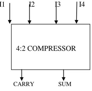
B. 4:2 compressor
As a solution to the delay of 3:2 compressor, a 4:2 compressor was proposed. The 4:2 compressor is built by connecting two 3:2 compressor in series.
I1 I2 I3 I4
CARRY SUM
Fig.4 Block diagram of compressor
Here, the architecture is connected in such a way that four of inputs are coming from the same bit position of the weight j while one bit is fed from the j-1 position. The outputs of 4:2 compressor consists of one bit in the position j and two bits inthe position j+1. The output Cout, being independent of the input Cin accelerates the carry save summation of the partial product. In a conventional Wallace tree multiplier the five partial product bits is compressed into 4 and so on. But in a Wallace tree multiplier modified with a 4:2 compressor, compresses the five partial product into three. This enables to minimize the irregularity in the delay of a Wallace tree multiplier.
Fig.5.Design of 4:2 compressor
A fast multiplier is usually composed of three parts (or modules).
• Partial product generation.
• A Carry Save Adder (CSA) tree to reduce the partial products’ matrix to an addition of only two operands • A Carry Propagation Adder (CPA) for the final computation of the binary result.
In the design of a multiplier, the second module plays a pivotal role in terms of delay, power consumption and circuit complexity. Compressors have been widely used to speed up the CSA tree and decrease its power dissipation, so to achieve fast and low-power operation. The use of approximate compressors in the CSA tree of a multiplier results in an approximate multiplier.
IV. RESULTS AND DISCUSSIONS
The program code is done in the VHDL language. VHDL is a very powerful, high level, concurrent programming language.
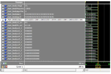
A. Simulation Result
Fig.5. Simulation result of the proposed multiplier.
B. Area and power analysis
Area and power analysis of FWM ,4 subblock and 3 subblock multipliers can be done by using Xilinx ISE Design suite 8.1. The results show that the proposed architecture is more efficient than existing ones. This approach may be well suited for multiplication of numbers with more than 16 bit size for high speed applications.
Table 2 Comparison of different schemes
V.CONCLUSION & FUTURESCOPE
speed of a multiprecision multiplier can be improved by using a modified Wallace algorithm. The modified algorithm uses a 4:2compressor.Thus it is possible to develop a multiprecision multiplier with optimum area, power and delay.
VI.ACKNOWLEDGMENT
The authors would like to thank for their constructive comments and valuable suggestions that helped in the improvement of this paper.
REFERENCES
[1] Xiaoxiao Zhang,Farid Boussaid and Amine Bermak “32 Bit X 32 Bit Multiprecision Razor-Based Dynamic Voltage Scaling Multiplier With Operands Scheduler” IEEEtransaction on Very Large Scale integration(VLSI)systems., Vol. 22, NO. 4, April 2014.
[2] Shaik.Kalisha Baba, D.Rajaramesh,”Design and Implementation of Advanced Modified Booth Encoding Multiplier,” International Journal of Engineering Science Invention, Vol 51, No.3, pp. 1701-1717, August. 2013.
[3] Laxmi Kumre, Ajay Somkuwar and Ganga Agnihotri, “Power efficient Carry propagate adder,” International Journal of VLSI design & Communication Systems (VLSICS).Vol.4, No.3, June 2013.
[4] Neeta Sharma,Ravi Sindal, “Modified Booth Multiplier using Wallace Structure and Efficient Carry Select Adder,” International Journal of Computer Applications((0975 8887))., Volume 68 No.13, April 2013.
[5] Xin Huang and Liangpei Zhang,”Variable Supply-Voltage Scheme for Low-Power High-Speed CMOS Digital Design,” IEEE journal of solid-state circuits, VOL. 33, NO. 3, pp. 161-172, March 1998.
[6] A. Bermak,D. Martinez,J.-L. Noullet,”High Density 16/8/4 configurable Multiplier,” IEEE Pvoc.-Circuits Devices Syst., Vol. 144, No. 5, October 1997.