Load-Case and -Combination Database
Heikki Raiko 1), Aarne Lipponen 2), Paul Smeekes 3) and Heli Talja 2)
1) VTT Energy, Finland
2) VTT Manufacturing Technology, Finland 3) Teollisuuden Voima Oy (TVO), Finland
ABSTRACT
The loading database is part of the pipeline analysis and monitoring system that will be used for nuclear power plant pip- ing systems and connected equipment at 2 Finnish nuclear power plants. These plants are situated in Olkiluoto and operated by Teollisuuden Voima OY (TVO). For a start the system will be used for class 1 piping systems only, but later on it may be extended to other systems where it is useful. The system will comprise a large set of process systems and components. Piping components, geometry, materials and systems are defined in an associated pipeline database [1]. Like the pipeline database, also the load-database will have a combined alphanumerical and graphical user-interface to show the user what the actual state is and what changes are made. The database system runs on a PC using commercially available database software [3].
This paper outlines the contents of the loading database system, which is being developed by TVO and VTT to facilitate the condition monitoring, aging and thermal transient follow-up, load history bookkeeping, documentation for component load specifications and related analyses for class 1 piping.
Basic dimensioning and necessary checks are made according to design standards like the ASME Code. This code de- fines allowable stress/strain levels in applicable service limits and rules how to estimate the usage factor of the cyclic loads. Normally those standards are applied that were valid when designing the plant or component. When ordering new compo- nents, they have to be compatible with the rules valid at that moment. This is the practice, at least in Finland. This means that in one plant different acceptance systems may exist simultaneously. This makes it difficult to find the applicable load data at a time.
The load database is designed to:
1. Contain and document the actually valid design load specification for any component or system inclusive service limits
2. Act, as far as possible, as an input database to perform stress, flexibility, fatigue and/or crack analyses for the pip- ing components or systems under consideration
3. Monitor and document the annual cumulative thermal transient events
4. Perform book-keeping of the load-cases and -combinations that are valid at a time and contain the connection be- tween old and new data
5. Give the structure for the result database where the significant results of analyses are stored.
Load-cases and -combinations are fully user configurable. In the present application either static or dynamic pressures, temperatures, weights, and forced displacements can be included as basic loads. These are included in the database or cou- pled as structured files in case of large data quantities. Presently, the database structure has been designed and is imple- mented. The items 1, part of item 2 and item 3 of the above list are implemented and test runs have been made for a piping system for at least part of the analysis types described under item 2. Most of the basic programming work will be finalized within one year. During the presentation the present status of the databases and program modules will be described.
INTRODUCTION
In the design analyses and safety assessment of nuclear power plant (NPP) components the loads are perhaps the most complicated input data to determine. The original design basis consists of a certain set of loads, which may also be applied in the case of component replacement. This set is formed by basic loads (load types or components), which then are combined and superimposed to combinations. Load combinations or operational events correspond to normal operation conditions, an- ticipated transients, incidents or accidents according to certain, conservative rules. The component replacement can also af- fect the loads on the system and often it must be demonstrated that the loads have not increased due to changes in the process or in the hardware. At the TVO Olkiluoto plant, the loads also have been re-assessed due to power uprate. So far, power uprate has been realized twice during the operational lifetime of the plant. The actual loads/events occurring at a plant may, on the other hand, differ significantly from the design load cases.
To keep track of all the data needed for piping analyses, loading events and to ensure that up-to-date information is easily accessible TVO has decided to organize it in a database system [1 ]. The loading database, which is part of this system, will contain as well design loads as information on actually occurred transients, preferably inclusive detailed information with regard to process parameters during the event.
SMiRT 16, Washington DC, August 2001 Paper # 1869
The load database is aimed to be a practical tool for bookkeeping of documentation of the design load specification for any component or system comprised. Thus it can be utilized in the case of making specifications for component replacement. It also shall act as a data source to perform stress, flexibility, fatigue and/or crack sensitivity or crack growth analyses for the piping components or systems. In this context the connection to a general piping database is an essential feature. Further, the database shall serve as bookkeeping and reporting tool for the annual cumulative thermal transient events and the follow-up of the rate between cumulative events and specified design events.
ORGANIZATION OF THE LOADS AND LOAD COMBINATIONS AT TVO
In the sections below the organization of the loads and load combinations as used at TVO is shortly described. This is necessary to understand the section on the database content and organization. As can be seen the present organization of the loads and load combinations, as was defined in the TVO plant modernizing project MFSAR (modernization of the FSAR), is based on the ASME design principles. In that project the loads and load combinations were updated, modernized and organ- ized in such a way that subsequent computer aided engineering is made possible. Below parallels will be drawn between the ASME rules and the MFSAR project. Later on, in the database contents chapter, parallels will be drawn between the MFSAR project and the actual database, thus establishing the connection between the database and the ASME.
Design Loads
According to the design practice, the design loading used in basic dimensioning shall be established on the highest pres- sure, temperature and coincidental design mechanical loads in operational conditions. Design loads for a mechanical NPP component or system is a set of simplified load cases and more complex load combinations that, in the plant design phase, are used for dimensioning and lifetime assessments. Basic dimensioning and necessary checks are made according to design standards like the ASME Code [2].
Basic Load Cases
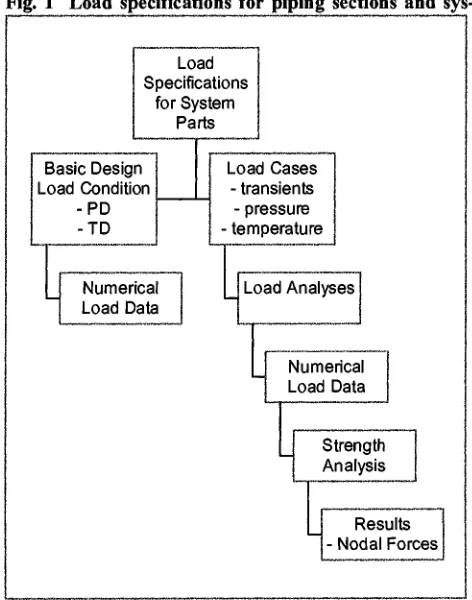
The load specification system is described in Fig. 1. An important part of the basic loading definition is the definition of piping sections where identical loading con- ditions prevail. The piping sections are defined on the base of system flow diagrams, see Fig. 5.
According to the Code [2], at least the following load types have to be taken into account when designing a component:
, Internal and external pressure;
, Impact loads, including rapidly fluctuating pres- sures;
, Weight of component and normal contents under operating or testing condition, including addi- tional pressure due to static and dynamic head of liquids;
, Superimposed loads such as other components, operating equipment, insulation, corrosion resis- tant or erosion resistant linings, and piping; , Wind loads, snow loads, vibration, and earth-
quake loads where specified;
, Reaction of supporting lugs, rings, saddles, or other type of supports;
, Temperature effects.
For many of the above-mentioned loads a separate load analysis has to be performed in order to determine the numerical load data that can be applied to the piping system finite element model.
Fig. 1 Load specifications for piping sections and sys-
Basic Design Load Condition
-PD -TD
"1
Numerical Load Data Load Specifications for System Parts Load Cases- transients
L.
t e m p e r a t u r e - pressure~
Load Analyses-[~ Numerical Load Data
~_~_ Strength
Analysis
[_1
LNodaISo~e
!
Plant Events and Load Combinations
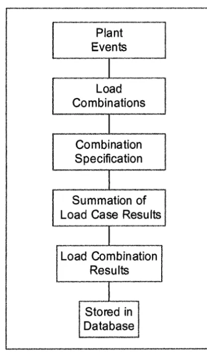
Definitions of coincidental load combinations for each system section are specified for all designed plant events. The load combination has an event identifier and it is de- fined as a sum of different loads. Each load combination belongs to certain service limit (A-D) and the service limit specifies the applicable stress limit rule according to [2]. Description of how the load combination results are derived from plant events is given in Fig. 2.
Cyclic Loading
The load combinations for service limit A and B have a specified number of cycles that is specified in the design phase. The fatigue lifetime of a component is assessed on the base of these cycles. Level C and D loads are not in- eluded in fatigue assessment due to the very low fre- quency of these events. Instead, in the event of level C or D incidents, inspection, testing and possible repair in plant systems and a possible shutdown is required.
Plant Operational History
The design lifetime of the plant has been assessed by making a cumulative fatigue assessment on the base of the specified number of the designed plant events. The actual cumulative usage factor can be calculated for any component or part of system at any time on the base of actual stored operational history of the plant. Accord- ingly, the operational history can be followed by collect- ing the operational data and storing it in chronological sequence in the database. Figs. 3 and 4 give the sequence for assessing design cumulative usage factor and actual cumulative usage factor.
Plant
Events
Load
Combinations
Combination
Specification
Summation of
Load Case Results
______I______
.Load Combination
Results
Fig. 2 Load combinations are derived from plant event descriptions. The effect of the load combina- tion is summed from the elementary results of the specified load case analyses, which results are stored in the database
Specification of Operational Cycles
1
Fatigue Analysis Using Load Combination
Results
Cumulative
Usage Factor
Plant Operational History
I
Fatigue Analysis Using Load Combination
Results
I
Actual Cumulative Usage Factor
I
t
DATABASE CONTENTS
General Properties
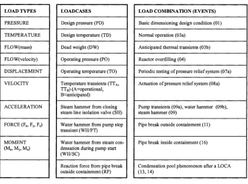
The system design load database contains the following information in applicable format: definition of piping sections, load cases, design base loads, coincidental load combinations and their area of influence and data related to cyclic loads. A reference to the applicable level of the service limit of the loading event is also given. Below these items are described in more detail. Some typical examples of loads, load cases and plant events are listed in Table 1.
TABLE I. Examples load types, Table la, load cases, Table Ib, and load combinations (events), Table Ic.
LOAD TYPES
PRESSURE
TEMPERATURE , ,
FLOW(mass)
FLOW(velocity)
DISPLACEMENT
VELOCITY
ACCELERATION
FORCE (~x, Vy, Vz)
MOMENT
(Mx, My,
Mz)i , i
LOADCASES
Design pressure (PD)
Design temperature (TD)
Dead weight (DW)
Operating pressure (PO)
Operating temperature (TO)
Temperature transients (TTA, TTB) (A=operational, B=anticipated)
Steam hammer from closing steam line isolation valve (SH)
Water hammer from pump stop transient (WH/PT)
Water hammer from steam con- densation during pump start (WH/SC)
Reaction force from pipe break outside containment (RF)
LOAD COMBINATION (EVENTS)
Basic dimensioning design condition (01)
Normal operation (03a)
Anticipated thermal transients (03b)
Reactor overfilling (04)
Periodic testing of pressure relief system (07a)
Actuation of pressure relief system (08a)
Pump transients (09a), water hammer (09b), steam hammer (09)
Pipe break outside containment (11)
Pipe break inside containment (16)
Condensation pool phenomenon after a LOCA (13,14)
Definition of Piping Sections and System Parts
An important part of the loading definition is the definition of piping sections where identical loading conditions prevail. Accordingly, the database contains definitions of system parts, for which the definition of load combinations is identical. A system part consists of one or, in most cases, more piping sections. A systematic naming procedure is applied throughout the database. The load specification for each piping section is separately defined and included in the database. And, respectively, the load combinations are defined and included in the database. An example of the piping section definition in a flow dia- gram is shown in Fig. 5.
A
B
C
-tN
Iii__ °
E
F
J ... i! ... N
Fig. 5 Example of piping section definitions, sections A-B, B-C, etc.
Definition of Loads for Piping Sections
All the loads are identified with a string and the related numerical information is stored in the database in one or more al- ternatives of the following:
, Numerical value of a constant load , Time history of a variable function load
, Definition of a dynamic response spectra (acceleration, frequency, damping) , Reference to a separate file of numerical load definition.
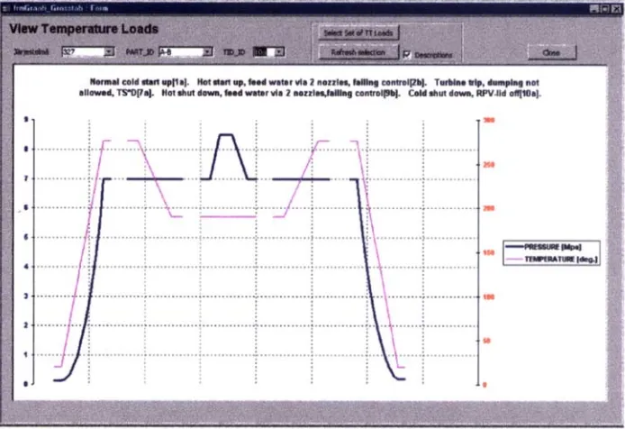
Examples of load types and cases are given in Tables la and lb above. A load definition in the database is accompanied by a reference to a load descriptive document. The reference documents are archived in a separate document database in TVO. An example of a visualization of time-dependent load definition in the database is shown in Fig. 6, below,
Normal cold starl up[la]. Hot slart up, feed water via 2 nozzles, failing control[2b]. Turbine trip, dumping not
allowed, TS"DITa]. Hot shut down, feed water via 2 nozzles, failing contrel[gb]. Cold shut down, RPV.Iid o~10a].
:::::::::::::::::::::::::::::::
t 6 ~ I . . . TEMPERATURE |deg.][
t00
0
Load Combinations
Load combinations are derived from plant operational events. An operational event is a chain of incidents in the NPP, which all cause different loading consequences in different system parts. In addition, during an operational event the systems interact in many ways in loading sense. Some interactions are direct and some are consequential. And some are coincident, some random and some are delayed (non-coincident). In loading database, the load combinations for system parts are defined as a direct or root-sum-square value sum expression of the pre-defined load cases, depending on the type of nature or origin of the load case.
Some typical examples of plant events in BWR-type NPP are given in Table lc. Defined load combination can be grouped in following categories according to design rules:
, Definition of design pressure and design temperature of the system part. Each load has an abbreviation for easier identification (for ex. system xx load case A01 = PD + DW, design condition, whereas A is the designation of the system part)
, Definition of operation condition loads (service limit A) of the system part, operation pressure, operation tempera- ture, operational mechanical loads (for ex. system yy load case B03a = PO + DW + TTA + D/B, service limit A, whereas B is the designation of the system part)
, Definition of anticipated operational transient loads (service limit B) of the system part, specified time histories for pressure, temperature, flow and mechanical loads, global vibration (for ex. system yy load case A09a = PO + DW + yyWH/PT & B09a = 0, service limit B, whereas A and B are the designation of the system part)
, Definition of minor accident loads (service limit C) of the system part, specified time histories for pressure, tempera- ture, flow and mechanical loads, global vibration (for ex. system xx load case A09b = 0 & B09b = PO + DW + yyWH/SC, service limit C, whereas A and B are the designation of the system part)
, Definition of design base accident and hypothetical accident loads (service limit D) of the system part, specified time histories for pressure, temperature, flow and mechanical loads, global vibration.
Cyclic Loading
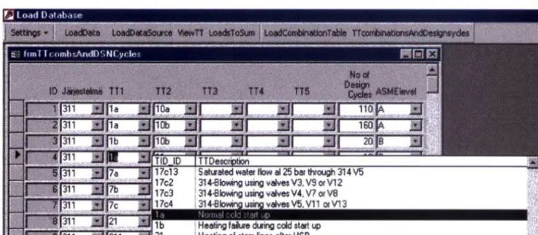
The number of design operational cycles for plant events is stored in the database and the number can be used in making fatigue analyses and lifetime estimates. The number of design cycles is used as a reference when making the annual summary report of the cumulated annual events and a comparison to the design thermal and pressure transient events for lifetime fol- low-up. An example of definition of a complete thermal transient cycle is shown in Fig. 7, below.
17c2 17c3 17c4
!S aturated water flow a125 bar through 314 V5 1314-Blowing using valves V3, V9 or V12
i
314.Blowing using valves V4, V7 or V8314-Blowina ueina valve: V5, V11 or V13
! Heating failure during cold start up ! Hp.~linn nf .~tp, m linp.,~ ~[l~.r H.RR
Fig. 7 Definition of thermal transient cycle in the database
Plant Operational History
Results for load cases
The loading database gives a structure also for the associated result database where the significant FE analysis results of load, stress and fatigue analyses are stored for post processing purposes according to corresponding logic. This system is also partly described above in Figs. 1 to 4.
DATABASE OPERATIONS
Storing of Data
The loading database shall be able to keep track of the following:
• Definition of load data for the piping sections and system parts for the different system parts affected by the load • The load cases for piping sections and load combinations for system parts that are valid at a time and the connec-
tion between old and new load data
• The number of design operational cycles for plant events
• The bookkeeping of actual plant events and cyclic loads in chronological sequence including registered associ- ated process parameters and the instant of time of the event
• Numerical data from load analyses • Numerical data from strength analyses
• Numerical data from load combination analyses • Numerical data from fatigue analyses.
In addition to storing the data, the database system can visualize the data in the form of data graphs, as shown in Fig. 6, or in the form of loading in a piping isometric drawing. The visualizing system is an important tool for validation of the manu- ally entered data.
Reporting Capabilities
The database system shall be able to make the following operations:
• Collect the loading data from the stored database for a piping system analysis and formulate it in an input-file for a piping analysis program
• Make a complete design load specification document for a specific piping component, line or system to be used, for instance, as load specification for piping component renewal
• Make an annual summary report of the accumulated annual events and a comparison to the design thermal and pressure transient events. This is to be used for lifetime monitoring.
To make safety, fitness and lifetime-related assessments for nuclear power plant components the necessary input data has to be reliable and up-to-date and it often has to be collected in a very short time. This might, for instance, be to assess the need for component repair during the annual outage, or for a temporary license application for continued operation for a damaged component.
SUMMARY
This paper outlines the contents of the loading database system, which is being developed by TVO and VTT to facilitate the condition monitoring, aging and thermal transient follow-up, load history bookkeeping, documentation for component load specifications and related analyses for class 1 piping. The loading database is operated in conjunction with other data- bases, namely, the piping geometry database, the reference report database, and the material database. All the analyses needed for assessments are made outside the database system using normal commercially available computer codes for load, stress, deformation, dynamics, or fatigue analysis. However, the results of the mentioned analyses can be stored in the data- base system for combination and archiving purposes. The database system is run on a PC using commercially available data- base software.
ACKNOWLEDGEMENTS
REFERENCES
1. Smeekes, P., (1), Lipponen, A., Raiko, H. and Talja, H. The TVO Pipeline Analysis and Monitoring System. SMiRT 16 Pa- per 1868, 2001.
2. ASME BOILER AND PRESSURE VESSEL CODE, SECTION III, Nuclear Power Plant Components, Division 1, Subsec- tion NB, Class 1 Components.