Thermal Analysis of Particulate Thermal
Interface Materials (TIMS) Using Finite
Element Analysis
Ammar Malayil1, Aneesh A2
M.Tech Student, Department of Mechanical Engineering, Malabar College of Engineering, Thrissur, Kerala, India1
Associate Professor, Department of Mechanical Engineering, Malabar College of Engineering, Thrissur, Kerala, India2
ABSTRACT: Particulate thermal interface materials (TIMs) are commonly used to transport heat from chip to heat sink. While high thermal conductance is achieved by large volume loadings of highly conducting particles in a compliant matrix, small volume loadings of stiff particles will ensure reduced thermal stresses in the brittle silicon device. Developing numerical models to estimate effective thermal and mechanical properties of TIM systems would help optimize TIM performance with respect to these conflicting requirements. Classical models, often based on single particle solutions or regular arrangement of particles, are insufficient as real-life TIM systems contain a distriubtion of particles at high volume fractions, where classical models are invalid. In our earlier work, a computationally efficient random network model was developed to estimate the effective thermal conductivity of TIM systems . This model is extended in this paper to estimate the effective elastic modulus of TIMs. Realistic microstructures are simulated and analyzed using the proposed method. Factors affecting the modulus (volume fraction and particle size distribution) are also studied. Thermal interface materials (TIMs) play a crucial role in removing waste heat from the chip. The heat flow depends on three factors namely (i) area of the surface (ii) Temperature difference and (iii) the convective heat transfer coefficient.
KEYWORDS:Thermal Interface Materials, Matrix, Convective Heat Transfer, Heat Flux.
I. INTRODUCTION
The past few decades have seen a revolutionary increase in computing performance and computers have become increasingly pervasive in all aspects of modern life. Evolution of the microprocessor is one of the most visible and representative facets of the computing revolution. Following Moore’s law [1], the semiconductor industry has successfully doubled transistor density every two years and the microprocessor has been the flagship product, successfully exploiting the increased performance with each new technology generation along Moore’s law. One of the historical consequences of increasing microprocessor performance is an associated increase in power dissipation. The microprocessor typically requires thermal management in three distinct environments
1) Cooling is required during functional test to prevent transient temperature rises from causing false performance readouts or failures.
formulating the interface material call for the development of analytical or numerical models to estimate the effective thermal and mechanical properties so they may be optimized by formulating the appropriate particle size distribution .
The length of heat sink fin is varied with different conductivities and convection coefficient. The optimum length is chosen in the analysis. The velocity of fan which is used to cool the microprocessor is varied with the values of 1.2 m/s, 2.2 m/s and 3m/s. This will consider as inlet boundary conditions. Composite materials with different combination are analysed in this journal. The composite materials were Alumina fillers in silicone matrix, Silver fillers in silicone matrix, Alumina fillers in epoxy matrix, Silver fillers in epoxy matrix and Copper filler in Silicone matrix.
II. LITERATURE REVIEW
The purpose of this literature review is to provide background information on the issues to be considered in this thesis and to emphasize the relevance of the present study. This treatise embraces some related aspects of polymer composites with special reference to their thermal analysis characteristics in heat sink. The topics include brief review:
1) On Variable Fin Length of Heat Sink 2) On Velocity of Cooling Fan.
3) On Thermal Analysis of different composite materials
Estimation of effective thermal and mechanical properties of Particulate thermal interface materials (TIMS) by a random Network model
Classical analytical models in literature such as the Maxwell’s model [3], Rayleigh’s model [4] and Bruggeman Differential Effective Medium (DEM) model [5] are valid only for isolated fillers and/or regularly arranged particles. Full-field simulations of particle ensembles were performed for high volume fractions [6] and were found to capture the near-percolation thermal transport in these materials accurately. However, these simulations were computationally expensive. A less expensive alternative using Batchelor’s analytical approximation for two particles in near contact [7] was developed by Kanuparthi et al. [1] and termed Random Network Model (RNM). This model was based on the observation that heat transport in the interface is predominantly through the particles when the particle to matrix conductivity ratio is very high.
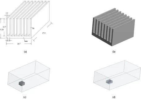
III.MODELLING
(a) (b)
(c) (d)
Fig. 1 Dimensions and Geometry (a) Heat sink Dimensions (b) CAD Model of Heat Sink (c) Combined Fluid and Solid Domain (d) Fluid Domain
IV.MESHING
Meshing is the process in which your geometry is spatially discretized into elements and nodes. This mesh along with material properties is used to mathematically represent the stiffness and mass distribution of your structure.
Your model is automatically meshed at solve time. The default element size is determined based on a number of factors including the overall model size, the proximity of other topologies, body curvature, and the complexity of the feature.
(a) (b)
Fig 2 Meshing Details (a) Meshed Geometry (b) Section of discretized geometry
No of Nodes : 18766
No of Elements : 100535
V. BOUNDARY CONDITONS
The following are the boundary conditions that are applied to the given model
Velocity of fan – 1.2 m/s, 2.2 m/s and 3 m/s
Fin Length – 27.9mm to 36mm.
Solid geometry is suppressed for the CFD Simulation
Steady Flow Energy equation and Viscous laminar flow is assumed for the simulation
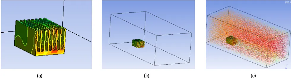
VI.RESULTANALYSIS
(a) (b) (c)
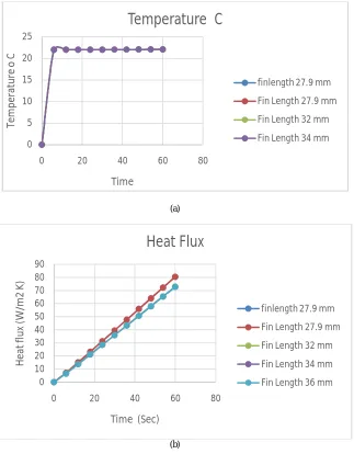
VARIATION OF FIN LENGTH
The fin length is varied with the range of 27.9 mm to 36 mm. The graph of Temperature, Heat Flux and Thermal
Resistance versus Time is plotted in different fin length.
(a) (b) 0 5 10 15 20 25
0 20 40 60 80
Te m p er at u re o C Time
Temperature C
finlength 27.9 mm
Fin Length 27.9 mm
Fin Length 32 mm
Fin Length 34 mm
0 10 20 30 40 50 60 70 80 90
0 20 40 60 80
H ea t fl u x (W /m 2 K )
Time (Sec)
Heat Flux
finlength 27.9 mm
Fin Length 27.9 mm
Fin Length 32 mm
Fin Length 34 mm
(a)
(b)
(c)
Table 6.1 Variation of Total Heat Flux
Sl No. Velocity
of Air Materials
Total Heat Flux (Maximum)
- m/s - W/m2
1 1.2 Aluminum filler with silicon matrix 1090.72
2 1.2 Aluminum filler with epoxy matrix 416.19
3 1.2
Silver filler with silicon matrix 432.13
4 1.2
Silver filler with epoxy matrix 1279.47
5 1.2 Copper filler with silicon matrix 1278.81
6 2.2
Aluminum filler with silicon matrix 664.39
7 2.2
Aluminum filler with epoxy matrix 241.16
8 2.2
Silver filler with silicon matrix 250.13
9 2.2 Silver filler with epoxy matrix 756.61
10 2.2
Copper filler with silicon matrix 756.30
11 3 Aluminum filler with silicon matrix 511.12
12 3 Aluminum filler with epoxy matrix 183.02
13 3
Silver filler with silicon matrix 189.51
14 3
Silver filler with epoxy matrix 571.42
15 3 Copper filler with silicon matrix 571.21
20 30 40 50 60 m p er at u re o C
Temperature C
VII.CONCLUSION
Different thermal interface materials are identified for the analysis and is numerically tested for the suitability as a potential replacement for conventional materials. The thermal conductivity of the TIM is calculated from equations. Intra molecular gap is varied to obtain different thermal conductivities for numerical analysis. Three type of analysis is carried out to study about the behavior of TIM as a viable replacement. First by varying the fin length, using different TIM materials and with different velocities. The first we have created atmosphere heat rejection from TIMs. Then we applied a forced air flow by applying three different conditions of velocities using fan. The composite material has set with 5 combination of composite materials. The fin length is varied and the optimum fin length is used in next phase. Temperature, Total Heat Flux, Thermal conductivity and Thermal resistance are calculated and plotted the graph with time. Following observations are obtained from the analysis
There is no considerable effects on heat flux and thermal resistance due to variations of effective fin length
Silver filler in Silicon matrix material combination shows better performance in terms of heat flux and thermal resistance.
Flow velocity is an important determinant of heat transfer in terms of electronic cooling
The future work can be done by changing the materials or by the different combination of composite materials can be analyzed. The turbulent flow can applied over the surface. The particle distance have done with small range. It can be decreased up to microstructure size and be used.
REFERENCES
[1] G. Moore, BCramming more components onto integrated circuits,[ Electronics, vol. 38, pp. 114–117, Apr. 19, 1965.
[2] Ravi Mahajan, Senior Member IEEE, Cooling a Microprocessor Chip, Proceedings of the IEEE Vol. 94, No. 8, August 2006
[3] http://www.informit.com/articles/article.aspx?p=482324&seqNum=8
[4] Heat and Mass Transfer Text Yunus C Cengel
[5] https://www.sharcnet.ca/Software/Ansys/17.2/enus/help/wb_sim/ds_Define_Resources_step.html
[6] Pavan Kumar Vaitheeswaran and Ganesh Subbarayan, Estimation of effective thermal and mechanical properties of Particulate thermal
interface materials (tims) by a random Network model, ASME 2017 International Technical Conference and Exhibition on Packaging and Integration of Electronic and Photonic Microsystems InterPACK2017 August 29-September 1, 2017
[7] Kanuparthi, S., Subbarayan, G., Siegmund, T., and Sammakia, B., 2008. “An efficient network model for determining the effective thermal conductivity of particulate thermal interface materials”. IEEE Transactions on Components and Packaging Technologies, 31(3).
[8] Dan, B., Kanuparthi, S., Subbarayan, G., and Sammakia, B., 2009. “An improved random network model for determining the effective thermal
conductivity of particulate thermal interface materials”. ASME 2009 InterPACK Conference, 2, pp. 69–81.
[9] Kareem A Jasim and Rihab N Fadhil 2018 J. Phys.: Conf. Ser. 1003 012082The Effects of micro Aluminum fillers In Epoxy resin on the thermal conductivity
[10] C. F. Lin, G. H. Wu, S. H. Ju, Investigation of Thermal Characterization of a Thermally Enhanced FC-PBGA Assembly, Published Online September 2013.
[11] D.D.L Chung, Thermal Interface materials, Journal of Material Science and performance Vol 10 (1) Feb 2001
[12] Rajlakshmi Nayak, Dr. Alok satapathy(2010).A study on thermal conductivity of particulate reinforced epoxy composites.
[13] K. Jung-il, P.H. Kang and Y.C. Nho, Positive temperature coefficient behavior of polymer composites having a high melting temperature, J.
Appl. Poly Sci., 92 (2004) 394–401.
[14] H. Wang, Y. Bai, S. Lui, J. Wu and C.P. Wong, Combined effects of silica filler and its interface in epoxy resin, J. Acta. Mater., 50 (2002)
4369–4377.
[15] William Callister D 2006 Jr Materials Science and Engineering An Introduction 7th Edition PP 520-528
[16] Kullör L P and Spriner 2003 Mechanics of Composite Structures (Cambridge University Press Stanford)
[17] P F Intropera and V Dewit 1981 Fundamental to Heat Transfer (John Willey and Sons Inc. USA)
[18] Kareem A Jasim and Rihab N Fadhil The Effects of micro Aluminum fillers In Epoxy resin on the thermal conductivity2018 J. Phys.: Conf.