Design and Fabrication of Cart with
Crank-Based Walking Mechanism
Satyala Stephen1, Dr. B. Chandra Mohana Reddy2
PG Research Scholar, Department of Mechanical (Product Design), JNTUA College of Engineering, Ananthapuramu,
A.P., India1
H.O.D & Assistant professor, Department of Mechanical, JNTUA College of Engineering, Ananthapuramu,
A.P., India2
ABSTRACT: To reduce the human effort at different work places the innovative machinery was developing and technological advancement taking place day by day. One of the problems which was faced by most of the farmers is carrying of Agri products, Fertilizers and Farming equipment etc. on rough/muddy/slippery terrains where the road transport is not established is very difficult to transport by completely wheel motion of vehicle. So here people transporting them by self-carrying or by using Bullock Carts. To reduce the human effort, there is a need of innovative cart which walks and carries the goods by means of walking mechanism.
The cart should work with the walking mechanism by means of linkages which walks like an animal (Oxen). The design consideration includes one should sit on the cart and be pedalled manually to walk on any terrain. The design challenges of this project is to stabilize the walking to move smoothly, turning directional control mechanism, speed control of the cart, stability of the cart and efficiency of the cart etc. This project aims to innovate the complete cart model to fulfill all the design considerations and challenges by means of computer aided Designing application NX 10.0. Later the walking mechanism is analyzed and simulated using NX. Then complete designed cart can be fabricated and assembled together to get the final prototype of the cart. Future scope and applications of this cart includes in the field of agriculture, manufacturing industries, food processing industries, mining fields, and logistics etc.
KEYWORDS: Bullock Cart, Effort, Linkages, Prototype, Speed Control, Walking Mechanism,
I. INTRODUCTION
It has been established that legged 0ff-r0ad vehicles exhibit better m0bility, 0btain higher energy efficiency and pr0vide m0re c0mf0rtable m0vement than th0se 0f c0nventi0nal tracked 0r wheeled vehicles while m0ving 0n r0ugh terrain. Alth0ugh legged walking mechanisms have a high p0tential in m0bility and energy efficiency on r0ugh terrain, they often inv0lve a large number of ge0metrical dimensi0ns, which makes it necessary to res0rt to optimization to achieve a high quality design. Reducing the energy l0ss has always been the interest in designing legged mechanisms.
Objectives:
The aim of this project is to create an energy efficient mechanism for the movement of a vehicle over variable terrain. My objectives are discussed below:
Energy efficiency:
Ability to avoid obstacles by stepping over them Statically stable during entire locomotive cycle
No control mechanism necessary Inspiration:
Theo Jansen mechanism also called as “Strand Beest Mechanism” designed is inspired by Jansen’s linkage, which is a pIanar mechanism designed by the kinetic sculptor Theo Jansen to simulate a smooth walking motion. He used these linkages in designing Iarge mechanical animals called ‘Strandbeests’ (literally meaning ‘beach beest’) that can live on their 0wn. He optimized the lengths of the Iinkages of the linkage to best simulate the gait of an animal. The optimizati0n of the link lengths for the Strand beest was done using a genetic alg0rithm.
Advantages of Walking:
Walking machines possess several advantages 0ver wheeled machines in areas 0f variable terrain. Consider a wheel m0ving a constant velocity V; every p0int on its perimeter is m0ving at a c0nstant velocity V tangent to the curve 0f the wheel. A comparable walking mechanism would be one which moves at a constant vel0city V and where the “fo0t” of the walker traces out a similar circular path with a constant velocity V at all points on the path. The most obvi0us advantage of the f0ot over the wheel is that the foot may step 0ver inconsistencies in the terrain. L0cal maxima and minima may be c0mpletely avoided by simply stepping 0ver them. This results in less l0ss of energy during loc0motion and allows the vehicle to maintain a constant ve0city and height 0ver variable terrain.
The benefits 0f walking over r0lling on r0ugh terrain: Higher energy efficiency, better fuel ec0nomy Increased speed
Greater m0bility
Improved is0lation from terrain inc0nsistencies
Less envir0nmental damage (both from paving and er0sion
II. LITERATURE REVIEW
Theo Jensen a Dutch kinetic artist who has attempted to create a bridge between art and engineering by focusing on biological nature, proposed a linkage mechanism to mimic the skeleton of animal legs. This is called “Theo Jansen mechanism” and provides the animal with a means of moving in a fluid manner.
The Klann linkage was developed by Joe Klann in 1994 as an expansion of Burmester curves which are used to develop four-bar double-rocker linkages such as harbour crane. This Klann mechanism is a planar mechanism converts the rotary motion of the crank to linear m0vement of the foot for one-half r0tation of the crank and raises the foot for the second half, returning it to the starting point.
M. H. Raiberthad Early research efforts in Boston Dynamics’ Big Dog that can control its forward speed, and although it moves with static stable gaits, it can achieve a dynamically balanced trot gait when moving at human walking speeds .
III. THEORY OF MECHANISMS
Classification of Mechanisms:
Mechanisms can be classified based 0n several fact0rs. Most c0mmonly used mechanisms are classified as follows:
a. Single Degree of Freedom Linkage Mechanisms:
A linkage mechanism with a single degree of freedom (DOF) means if a single joint is moved, and then all of the remaining joints have to m0ve in response. With mechanical walkers, the joint that is moved is a crank that is connected to a crankshaft and m0tor. Single DOF mechanisms can make designing walking robots both easier, and harder.
b. Path Followed Mechanisms: i. Straight-Line Mechanisms:
Straight-line linkages are especially useful since they transf0rm circular motion at one joint to linear motion at another joint, or vice versa, and all0wed the steam engine t0replace the water wheel, dramatically accelerating the industrial revolution.
ii. The "Ideal" Foot-Path Mechanisms:
We call the path drawn by a foot as the axle is rotated the "foot-path", better kn0wn to engineers as a coupler curve: what constitutes an "ideal" foot-path depends on the scale of your build. In other words, when the feet are in contact with the ground:
1. Their path should be as flat as possible so that the machine doesn't bounce, which would also increase the torque and power required to walk, as you can see in this experiment with Walking Mechanism.
2. Their horizontal speed sh0uld be as uniform as possible so that they don’t skid or shake the machine. If the foot-speed varies, as you can see in this experiment with Klann's mechanism.
Design considerati0ns for mechanisms:
a. Minimizing the Number of Legs Required by Walkers
To minimize the number of legs a walker requires, the linkage sh0uld maximize the percentage 0f time the foot is in contact with the ground per axle rotation. To say it another way, the linkage sh0uld minimize the percentage of time it takes the f0ot to be lifted and returned to the fr0nt of the foot-path.
b. Walker Stability
The requirements for walker stability vary greatly depending on their size. Small-scale, 8-legged walkers can often get away with only three feet on the ground, which may cause them to shuffle or lumber as they move about, but may not impair their ability to walk. H0wever, the larger the walker is, the more the lumbering will take its toll on walking performance, efficiency, and ultimately, the parts.
c. Sideways Forces on Legs
Z dimension has n0 impact on the linkage characteristics of planar mechanisms, building the leg secti0ns wide is incredibly imp0rtant from a structural engineering perspective; otherwise sideways forces and resulting torque on the joints can snap the legs like twigs, especially when turning walker’s tank-style. The way that we s0lved this problem with Walking Mechanism was to truss each leg in the sideways dimension, creating lightweight but effectively very wide parts that could withstand sideways forces.
d. Transmission of Torque (twisting force)
Mechanical walkers typically have 8 to 12 legs configured in front/back pairs, staged out from the frame. This means that torque has to be transferred all the way from the inner frame to the outside leg pair. This can be achieved through a system of cranks attached to crankshafts (axles). However, this system can also become overextended and begin to bow under the robot's weight.
IV. DESIGNOFWALKINGMECHANISM
mechanism. This retractable toe and heel is useful for keeping leg on the ground for the support and retract quickly when the leg is in returning stage. It has one crank which can be driven to walk on the terrain of leg mechanism.
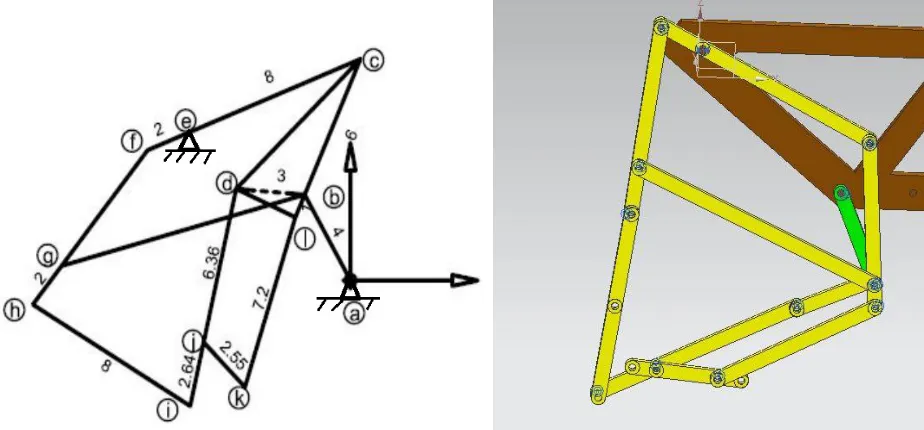
Walking Mechanism Linkage Dimensions:
Figure 4.1 Walking Mechanism with dimensions is in cm. Figure 4.2: CAD Model of Walking Mechanism Leg
Characteristics Walking Mechanism:
1. Eight Legs with a gait that mimics a galloping horse
2. Walks most efficiently with the addition of a "heel" on both smooth and rough terrain. 3. This mechanism is also steerable by driving one side forward and other in reverse of the cart.
Design Application of the Walking mechanism:
By using the walking leg mechanism an innovative cart is designed with eight legs which are similar to that of traditional oxen cart. In this design front two legs are connected to frame by connecting rod which is out of phase by 1800 and another set of legs are connected to back of the frame. Front two legs and back two legs are coupled by a connecting rod or by using gears to give the input torque to the four legs simultaneously. So this forms a four legged walking machine and looks like horse with four legs. Next same four legged walking machine is connected by main frame of the cart and coupled both machines by crank of which is having pedal. This is well arranged in such a way one can sit on the main frame seating and it can be pedaled to drive like bullock cart.
V. KINEMATICANALYSISCALCULATIONS
5.1 Introduction:
In the analysis and design of mechanisms, kinematic quantities such as displacements, velocities and accelerations are of great engineering importance. Displacements and velocities give an insight into the functional behavior of the mechanism. The acceleration, on the other hand, are related to forces by Newton’s principle which themselves are related to stresses and deformations in the mechanism’s components.
5.2 Kinematic Analysis
5.1.1 Position Analysis of Mechanism
Four bar planar mechanism have only one DOF so that only one parameter is needed to completely define the position of all the links.
5.1.2 Velocity Analysis:
Once a position analysis is over, the next step is to determine the velocities of all links and points of interest in the mechanism. There are different methods and approaches are available to determine the velocities of each link of mechanism. Few of them are mention here:
Relative velocity method (Graphical) Instant centre’s method (Graphical) Analytical method
To calculate the velocities of links at different interval of crank rotation, analytical method can be more suitable for computer programming. The velocity analysis is the prerequisite for acceleration analysis which further leads to force analysis of t various links of a mechanism.
5.4 calculations of degrees of freedom of the mechanism:
According to Gruebler’s criterion Degree of freedom for planar mechanism is as follows: F = 3(N-1) – 2P1- 2P2
Where N = Total Number of Links in a mechanism F = Degrees of Freedom
P1 = Number of pairs having one degree of freedom,
P2 = Number of pairs having two degrees of freedom,
P1 = N + (L – 1) Where L = Number of Loops
In the walking mechanism: Binary Links = 9 Quaternary Link = 1 Total number of Links = 10 No of Loops (L) = 3 P1 = 10 + 3 – 1 = 12
F = 3(10-1) – 2(12) F = 27 – 24
Degrees of Freedom of Mechanism F = 3
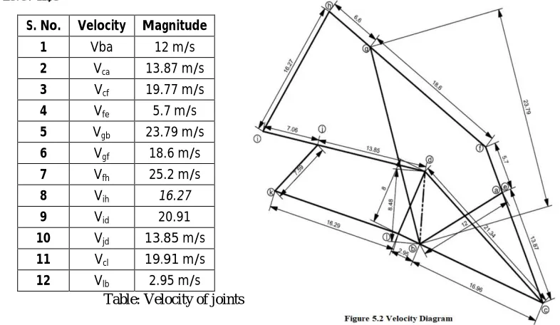
5.5 Calculations of Velocities at Each Joint: To find the linear velocity of link ab:
Let’s take angular velocity (ω) of link ab = 300 rad/sec We know that length of link ab = 40 mm
Vba = 300 × = 12 m/s
Vba = 12 m/s
Velocity Vca = Vba+ Vcb(vector addition)
To find the Vcb we have to draw a line from a of considerable length ┴ to link CB
Then intersection of line cb and ec is the point ‘c’ and length of ‘cb’ and ‘ec’ can be measured by scale. Therefore
Vca = 13.87 m/s
Table: Velocity of joints
Foot Path Trace of the Mechanism:
In the walking mechanism movement path can be divided into four parts: the support, lift, retract, and lower phases. Throughout the support phase, the foot is ideally in contact with the ground and it should take more time out of all four phases. Because whenever the leg is in contact with the ground it gives more stability to the walking machine. In the lift phase it takes higher position from the ground which should be gradually increases its velocity. In the Retract or return phase the walker should move with higher velocity in less time so that walking can be stabilized and also motion will be advantage to walk more distance in less time. For the Last phase the motion should be gradually decrease and it should reach the ground without impact so that motion of the walking will be steady and smooth.
Figure 5.3 Foot Path Trace followed by ‘heel’ and ‘toe Figure 6.1 Fabricated Prototype Model of the walking S. No. Velocity Magnitude
1 Vba 12 m/s
2 Vca 13.87 m/s
3 Vcf 19.77 m/s
4 Vfe 5.7 m/s
5 Vgb 23.79 m/s
6 Vgf 18.6 m/s
7 Vfh 25.2 m/s
8 Vih 16.27
9 Vid 20.91
10 Vjd 13.85 m/s
11 Vcl 19.91 m/s
12 Vlb 2.95 m/s
VI. RESULTSANDDISCUSSIONS
6.1 Introduction:
In the walking mechanism movement path can be divided into four parts: the support, lift, retract, and lower phases.
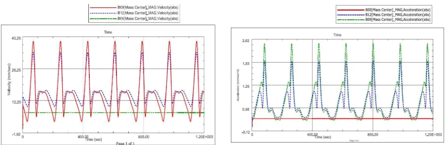
Figure 6.2 Velocities vs. Time Graph of Crank, Toe and Heel Figure 6.3 Acceleration vs. Time Graph of Crank,
6.2 Velocity Graph:
From the velocity vs. time graph it can seen that for complete rotation of the crank of given input velocity 12 mm/sec (green color), the toe(B09 –red color ) and heel (B12 – blue color) is returning with less time (approximately 30 sec) with high velocity (up to 39 mm/sec).
For the lowering phase the toe (B09 –red color) and heel (B12 – blue color) was taking 20 sec only with velocity of 10 mm/sec means gradually reaching the ground.
During the support phase the toe (B09 –red color) and heel (B12 – blue color) was taking 60 sec with velocity of 17 mm/sec.
For the lifting phase the toe (B09 –red color) and heel (B12 – blue color) was taking 30 sec with velocity of 10 mm/sec means gradually rising from the ground.
6.3 Acceleration Graph:
From the Acceleration vs. time graph it can seen that for complete rotation of the crank of given input Acceleration of 12 mm/sec2 (red color), the toe(B09 –green color ) and heel (B12 – blue color) is retracting with less time (approximately 10 sec) with high acceleration (up to 2.5 mm/sec2).
For the lowering phase the toe (B09 –green color) and heel (B12 – blue color) was taking 20 sec with acceleration of 0.55 mm/sec2 means gradually reaching the ground.
During the support phase the toe (B09 –red color) and heel (B12 – blue color) was taking 60 sec with acceleration of 0.35 mm/sec2.
For the lifting phase the toe (B09 –red color) and heel (B12 – blue color) was taking 30 sec with acceleration of 0.46 mm/sec2 means gradually rising from the ground.
VII. CONCLUSIONS
From the above results it can be seen the objective are achieved which are required for the smooth running of the walking mechanism. The following conclusions can bedrawn from the designed mechanism:
Ability to avoid obstacles by stepping over them because of the path followed by the leg toe and heel.
Because of the more taking time in support phase and there will be four legs will be in contact with ground it can be statically stable during entire locomotive cycle
Durable joints/hinges/moving parts which will not become blocked by debris over time It can made with inexpensive materials like plastic components
It utilizes less power for movement of legs compared to traditional system i.e wheels on the uneven surfaces, steps climbing, rock or hill areas therefore it is energy efficient.
No control mechanism necessary for movement like hydraulic systems and control systems etc.
REFERENCES
[1]G. Lokhande*, V.B. Emche** Mechanical Spider by Using Klann Mechanism Assistant professor, Department of Mechanical Engineering ShriDattaMeghe Polytechnic, HingnaNagpur-16.India email: [email protected] , [email protected]
[2] Mechanical Spider by Using Klann Mechanism by engineering &science channel by https://www.youtube.com/alexander85074
[3] Flash animation of one possible con guration of the Klann linkage at http://www.mekanizmalar.com/mechanical-spider.html where we can change the dimensions of the each link
[4] Mechanical Spider by KLANN RESEARCH AND DEVELOPMENT, LLC http://www.mechanicalspider.com/ [5] Thoe Jansen linkage : www.theojansen.com
[6] Shieh, W.B., Tsai, L.W. and Azarm, S., “Design and optimization of a one-degree-of-freedom six-bar leg mechanism for a walking machine”, Journal of Robotic Systems, Vol. 14, No. 12, pp. 871–880, 1997.
[7] www..diywalkers.com